
Related Manuals for SCHUNK VERO-S NSL mini 100


Summary of Contents for SCHUNK VERO-S NSL mini 100
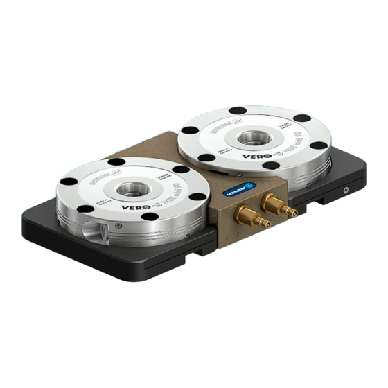
- Page 1 VERO-S Clamping station NSL mini 100 Assembly and Operating Manual Translation of the Original Operating Manual...
- Page 2 Imprint Imprint Copyright: This manual is protected by copyright. The author is SCHUNK SE & Co. KG. All rights reserved. Technical changes: We reserve the right to make alterations for the purpose of technical improvement. Document number: 1155723 Version: 02.00 | 19/01/2024 | en...
-
Page 3: Table Of Contents
Table of Contents 1 General ..................... 5 About this manual................1.1.1 Illustration of safety notes ............1.1.2 Applicable documents ..............1.2 Warranty ................... 1.3 Scope of delivery................. 1.3.1 Accessories ................2 Basic safety notes................. 2.1 Appropriate use .................. 2.2 Inappropriate use ................2.3 Structural changes................ - Page 4 5.4.1 Unlocking connection..............22 5.4.2 Turbo connection ............... 22 5.5 Connection of several NSL mini 100-2 clamping stations....... 22 5.6 SPA mini 20, SPB mini 20, SPC mini 20 clamping pins........24 6 Maintenance and care ................27 6.1 Ambient conditions and operating conditions ........... 27 6.2 Disassembly and assembly of the Clamping Station........
-
Page 5: General
Catalog data sheet for the attached product * Technical data sheet for optional attachments * Approval drawings The documents labeled with an asterisk (*) can be downloaded from schunk.com. 01.00 | NSL mini 100 | VERO-S Clamping station | en | 1155723... -
Page 6: Warranty
General 1.2 Warranty The warranty for standard products is 24 months from the date of delivery from the factory, or 50,000 cycles* for manually operated clamping devices and 500,000 cycles* for power operated clamping devices. For special clamping devices, it is 12 months from the date of delivery from the factory, assuming appropriate use in accordance with the following conditions: Observe the applicable documents,... -
Page 7: Basic Safety Notes
100 RPM without consulting SCHUNK. the product is not fully covered by the pallet, the fixture or the workpiece. -
Page 8: Spare Parts
Using unauthorized spare parts can endanger personnel and damage the product or cause it to malfunction. Only use original spare parts and spares authorized by SCHUNK. 2.5 Ambient conditions and operating conditions Required ambient conditions and operating conditions Incorrect ambient and operating conditions can make the... -
Page 9: Personal Protective Equipment
Basic safety notes The following personnel qualifications are required for the various activities on the product: Qualified electrician Qualified electricians have the professional training, knowledge, and experience to work on electrical systems, to recognize and avoid potential dangers, and know the relevant standards and regulations. -
Page 10: Protection During Commissioning And Operation
Basic safety notes 2.11 Protection during commissioning and operation Falling or violently ejected components Falling and ejected components can lead to serious injury or death. Take suitable protective measures to secure the danger zone. Manual loading If the clamping device is closed, the clamping pallet rests on the clamping slides after loading. -
Page 11: Fundamental Dangers
Basic safety notes 2.14 Fundamental dangers General Disconnect power sources before installation, modification, maintenance, or calibration. Ensure that no residual energy remains in the system. Do not reach into the open mechanism or movement area of the product during operation. 2.15 Protection against dangerous movements Safe condition Quick-change pallet system with or without chuck jaws clamped... - Page 12 Basic safety notes WARNING Risk of injury when the clamping pin or clamping ring axis is in a horizontal position or during overhead applications due to the device or pallet falling down. Use a crane or a transport truck when transporting workpieces or clamping pallets.
-
Page 13: Technical Data
If the quick-change pallet system is to be used outside the specified welding currents, please contact your SCHUNK contact person. 01.00 | NSL mini 100 | VERO-S Clamping station | en | 1155723... -
Page 14: Construction
Construction 4 Construction Components of a clamping station Alignment for T-nuts Quick-Change Pallet Module Screw-on point Base plate Type plate Alignment edge Air connections Versions Alignment grooves for clamping pallet (2 x 90°) Single clamping station Radial arrangement of the quick change clamping modules Alignment edge Linear arrangement of the quick change clamping modules... -
Page 15: Assembly
Assembly 5 Assembly 5.1 Screw tightening torques Tightening torques for screw connections with screws according to DIN 7984 (strength class 10.9) Screw size Tightening torque (Nm) Tightening torques for screw connections with screws according to ISO 4762 (strength class 10.9) Screw size Tightening torque (Nm) 5.2 General assembly instructions... -
Page 16: Fastening And Alignment Of The Clamping Station
Assembly 5.3 Fastening and alignment of the clamping station CAUTION An equal height of the modules is not achieved before the clamping station has been properly fastened on the machine table. The clamping station is to be fastened with the BRR mini 40 clamp blanks which are available as accessories. -
Page 17: Clamping Station Nsl Mini 100-1-V1
Assembly Mounting variants on different machine tables Spacing of table slots: 50 / 100 mm Spacing of table slots: 80 mm Spacing of table slots: 63 mm 5.3.1 Clamping station NSL mini 100-1-V1 For alignment and fastening, see the illustrations in the chapters "Assembly"} 4 [/ 14], "Fastening and alignment of the clamping stations"} 5.3 [/ 16]... -
Page 18: Clamping Station Nsl Mini 100-2
Assembly 5.3.2 Clamping station NSL mini 100-2 For alignment and fastening, see the illustrations in the chapters "Assembly"} 4 [/ 14], "Fastening and alignment of the clamping stations"} 5.3 [/ 16] and "Alignment and screw-on points"} 5.3.5 [/ 20]. For the required screw tightening torques, see chapter "Screw torques"} 5.1 [/ 15]. -
Page 19: Clamping Station Nsl Mini 100-3
Assembly property class of 10.9 in accordance with DIN ISO 4762. A through- hole for a mounting screw can be drilled in the blank mounting rings by the customer. To increase the clamping pressure, the mounting hole should be positioned close to the inner protrusion. -
Page 20: Clamping Station Nsl Mini 100-4
Assembly 5.3.4 Clamping station NSL mini 100-4 The NSL mini 100-4 clamping station consists of two NSL mini 100-2 clamping stations that are connected to the coupling set (scope of delivery NSL mini 100-4). The air supply for the unlocking functions and turbo function is continued via the connection adapters. -
Page 21: Connections
Assembly Alignment elements and screw-on points of the NSL mini 100-3 Screw-on points Ausrichtnuten für Nutensteine Center bore hole for alignment pin Screw-on points beneath the Clamping surface clamping modules for BRR mini 40 clamp blanks 5.4 Connections The NSL mini clamping station in standard design is actuated via an air connection with a closing nipple and closure coupling. -
Page 22: Unlocking Connection
Assembly 5.4.1 Unlocking connection If the unlocking connection of the clamping station is actuated, all the modules will be unlocked at the same time. Clamping pallets, devices or workpieces can be removed from the clamping station, or be inserted now. 5.4.2 Turbo connection The clamping station features a turbo connection as standard equipment. - Page 23 Assembly When connecting several clamping stations, make sure that the symbols of the operating type are connected linearly one after the other. The alignment edges of the clamping stations can be used for orientation. First establish the air connection between the two clamping stations.
-
Page 24: Spa Mini 20, Spb Mini 20, Spc Mini 20 Clamping Pins
This is why only screws of strength class 12.9 may be used. Only original SCHUNK clamping pins may be used. If the clamping pins are to be used in customer-owned devices, the customer must provide sufficiently dimensioned threaded holes or a sufficiently thick mounting material. - Page 25 Assembly Usage/arrangement of the different types of clamping pins Application: pallet with one clamping area Clamping pin type A, with positioning accuracy Indexing pin for position orientation and torque absorption on NSL mini 100-1-V1 Application: pallet with three clamping areas Clamping pin type A, with positioning...
- Page 26 Assembly Application: pallet with four clamping areas Clamping pin type A, with positioning accuracy Clamping pin type B, for positioning in one direction Clamping pin type C, with centering play of 0.1 mm 0.015 for type B 0.015 for type C Arrangement on the same clamping station 01.00 | NSL mini 100 | VERO-S Clamping station | en | 1155723...
-
Page 27: Maintenance And Care
Risk of injury and risk of damage to the clamping module when opening the housing cover. If the clamping module has to be disassembled, send the module to SCHUNK for repair. The covers of the clamping modules are spring preloaded and must only be removed and installed by trained specialist personnel and in line with the appropriate removal and installation manual. -
Page 28: Disassembly And Assembly Of The Clamping Station
9. Clean all parts thoroughly and check for damage and wear. Damaged and worn parts must be replaced. Replace damaged parts only with original SCHUNK replacement parts! Assembly of the clamping station in reverse order. -
Page 29: Functionality Test
Maintenance and care 6.3 Functionality test The functional test should confirm proper functioning of the quick change clamping systems for several coupled clamping stations, if applicable. Correct functioning is ensured if: the clamping slides move smoothly at the minimum system pressure (5 bar) the coupled clamping station is controlled via the air transfer interface... -
Page 30: Troubleshooting
Troubleshooting 7 Troubleshooting The clamping area does not unlock or does not unlock properly Possible cause Remedial measures Pressure below minimum Check operating pressure (min. 5 bar) The module was not operated with oiled Install maintenance unit with oiler compressed air Defective air connections Check air supply Excess tensile load on clamping pins... -
Page 31: Storage
Storage 8 Storage When storing the product for a longer period of time, observe the following points: Clean the product and lubricate it lightly. Store the product in a suitable transport container. Only store the product in dry rooms. Protect the product from major temperature fluctuations. NOTE: Before recommissioning, clean the product and all attachments, check for damage, functionality and leaks. -
Page 32: Sealing Kits, Accessory Kits And Parts Lists
Sealing kits, accessory kits and parts lists 9 Sealing kits, accessory kits and parts lists When ordering spare parts, the type, size and, if possible, the serial number of the clamping system must always be stated to avoid delivery mistakes. Seals, sealing elements, fittings, springs, bearings, screws, wiper bars and parts that come into contact with the workpiece are not covered by the warranty. - Page 33 Sealing kits, accessory kits and parts lists NSL mini 100-2 (ID 0435220) Item Designation Quantity Note Base plate Housing Adjustment disc Locking plug (plastic) NSE mini 90 Screw Screw Locking screw G1/8" with sealing ring Set-screw Set-screw O-ring O-ring Locking nipple Screw Closure coupling End caps...
- Page 34 Sealing kits, accessory kits and parts lists NSL mini 100-3 (ID 0435230) Item Designation Quantity Note Base plate Housing Locking plug (plastic) NSE mini 90 Set-screw Set-screw Set-screw O-ring O-ring Countersunk screw Locking screw G1/8" with sealing ring Locking nipple Screw Closure coupling End caps...
-
Page 35: Drawings
Drawings 10 Drawings NSL mini 100-1-V1 01.00 | NSL mini 100 | VERO-S Clamping station | en | 1155723... - Page 36 Drawings NSL mini 100-2 O-ring section ** Scope of delivery of the quick change pallet system 01.00 | NSL mini 100 | VERO-S Clamping station | en | 1155723...
- Page 37 Drawings NSL mini 100-3 O-ring section ** Scope of delivery of the quick change pallet system 01.00 | NSL mini 100 | VERO-S Clamping station | en | 1155723...
- Page 38 01.00 | NSL mini 100 | VERO-S Clamping station | en | 1155723...
- Page 39 H.-D. SCHUNK GmbH & Co. Spanntechnik KG Lothringer Str. 23 D-88512 Mengen Tel. +49-7572-7614-0 info@de.schunk.com schunk.com Folgen Sie uns I Follow us Wir drucken nachhaltig I We print sustainable...
- Page 40 NSL, NSD, NST, GSL, SSN, SSN turn Heinz-Dieter SCHUNK GmbH & Co. Spanntechnik KG certifies that the above-mentioned products, when used as intended and in compliance with the operating manual and the warnings on the product, are safe according to the national regulations and: −...
Need help?
Do you have a question about the VERO-S NSL mini 100 and is the answer not in the manual?
Questions and answers