
Subscribe to Our Youtube Channel
Related Manuals for SCHUNK VERO-S NSR mikro 60


Summary of Contents for SCHUNK VERO-S NSR mikro 60
- Page 1 Translation of Original Operating Manual VERO-S Robot Coupling for Pallet Handling NSR mikro 60 / PKL mikro 60 Assembly and Operating Manual Superior Clamping and Gripping...
- Page 2 Imprint Copyright: This manual is protected by copyright. The author is SCHUNK GmbH & Co. KG. All rights reserved. Any reproduction, processing, distribution (making available to third parties), translation or other usage - even excerpts - of the manual is especially prohibited and requires our written approval.
-
Page 3: Table Of Contents
Table of Contents Table of Contents 1 General ........................5 1.1 Presentation of Warning Labels ................5 1.2 Applicable documents ....................6 2 Basic safety notes ..................... 7 2.1 Intended use ......................7 2.2 Not intended use ...................... 8 2.3 Notes on particular risks ................... 8 2.4 Notes on safe operation .................. - Page 4 Table of Contents 9 Seal kit and part lists ....................41 9.1 Sealing Kit List ......................41 9.2 Parts Lists ........................ 42 10 Assembly drawing ....................44 11 Sensors ........................45 12 Declaration of incorporation ................... 52 13 Appendix on Declaration of Incorporation ............... 53 01.00|1430718_NSR mikro 60 / PKL mikro 60 |en...
-
Page 5: General
General General This operating manual is an integral component of the product and contains important information on safe and proper assembly, commissioning, operation, care, maintenance and disposal. This manual must be stored in the immediate vicinity of the product where it is accessible to all users at all times. Before using the product, read and comply with this manual, especially the chapter “Basic safety notes”.(... -
Page 6: Applicable Documents
Information about avoiding material damage. Applicable documents • General terms of business * • Catalog data sheet of the purchased product * The documents marked with an asterisk (*) can be downloaded on our homepage schunk.com 01.00|1430718_NSR mikro 60 / PKL mikro 60 |en... -
Page 7: Basic Safety Notes
Only original SCHUNK spare parts may be used. Intended use The VERO-S robot coupling is intended for pallet handling with a robot or similar appropriate technical devices. -
Page 8: Not Intended Use
• It is used as load handling or lifting equipment. • It is used for turning applications without consulting SCHUNK. • It is used in working environments that are not permissible. • People work on machines or technical equipment that do not comply with the EC Machinery Directive 2006/42/EC, disregarding the applicable safety regulations. - Page 9 Basic safety notes WARNING Risk of injury due to falling device, pallet or workpiece if the clamping pin is loosened erroneously or as a result of negligence. • During operation, erroneous or negligent loosening of the clamping pin must be prevented using suitable countermeasures (disconnecting the power supply after locking, use of check valves or safety switches).
- Page 10 Basic safety notes CAUTION Risk of injury due to compressed air hoses coming loose when connected improperly. • Use check valves or safety switches. • The danger zone must be surrounded by a protective enclosure during operation. CAUTION Risk of slipping or falling if the operational environment is not clean (e.g.
-
Page 11: Notes On Safe Operation
If the robot coupling is to be operated in an environment with abrasive dusts or corrosive or caustic fumes or fluids, prior approval must be obtained from SCHUNK. 01.00|1430718_NSR mikro 60 / PKL mikro 60 |en... -
Page 12: Holding Force And Screw Strength
This is why only screws of strength class 12.9 may be used. Only original SCHUNK clamping pins may be used. If the clamping pin is to be used in customer-specific devices, the customer must provide a sufficiently dimensioned pallet coupling or a sufficiently thick mounting material. -
Page 13: Organizational Measures
Only allow specialists to remedy malfunctions. Spare parts Only use original SCHUNK spare parts. Environmental regulations The applicable environmental regulations must be observed for all maintenance and repair work. -
Page 14: Warranty
Scope of Delivery Warranty If the product is used as intended, the warranty is valid for 24 months from the ex-works delivery date under the following conditions: • Observe the applicable documents, ( 1.2, Page 6) • Observe the ambient conditions and operating conditions •... -
Page 15: Technical Data
Technical Data Technical Data Designation / Type NSR micro 60 1357111 Max. torque Mx * 15 Nm Max. torque Mz * 32 Nm Max. transport weight 10 kg Pull-down force without turbo 500 N Pull-down force with turbo 1500 N Pull-down stroke 0.1 mm Actuating pressure... -
Page 16: Calculation Of Permissible Transport Load
Technical Data Calculation of Permissible Transport Load The robot coupling is limited to a maximum permissible torque at the coupling interface. The dynamic load when using the robot system for handling results in acceleration and deceleration forces that have to be taken into consideration for the transport load. To operate the robot coupling with dynamic handling, it is essential for the maximum acceleration of the machine to be known. - Page 17 Technical Data Determination of formula values: = 0.1 kg pallet coupling, type: PKL mini 100 (aluminum) = 0.5 kg clamping pallet, type: PAL A 399 x 159 (aluminum) = 9 kg (example value) transport load I = 60 mm = 0.06 m (example value) Calculating the acceleration force: Maximum permissible torque for NSR micro 60: M = 15 Nm Result of calculation:...
-
Page 18: Assembly
Assembly Assembly Pre-assembly measures Carefully lift the product out of the packaging (e.g. with suitable lifting equipment). CAUTION Risk of injury due to sharp edges and rough or slippery surfaces. • Wear personal protective equipment, particularly protective gloves. Check that the delivery is complete and that there is no transport damage. -
Page 19: Screw Tightening Torques
Assembly Screw tightening torques Screw tightening torques for mounting the robot coupling on the robot flange. Screw tightening torques for mounting the quick- change clamping pin on the pallet coupling and for the tension screws for the clamping pallet. (Screw quality 12.9) Screw size Screw tightening torques M (Nm) -
Page 20: Mounting And Connection
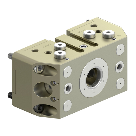
Assembly Mounting and Connection Request our installation drawings if doing the installation yourself. The NSR micro 60 is fixed in place with 5 M3 screws. Two mounting screws are used as fitting screws for positioning the robot coupling precisely on the necessary robot flange. Precise alignment and positioning of the robot coupling requires that the fitting bores Ø... - Page 21 Assembly Mounting 01.00|1430718_NSR mikro 60 / PKL mikro 60 |en...
- Page 22 Assembly Item Description Cylindrical screw (3x) Fitting screw for centering in middle axis Fitting screw for aligning diagonally offset Customer-specific robot flange Sensor cables The air connection takes place via the M3 coupling holes at the side as standard. Straight or angled pneumatic screw connections can be fitted for the air supply.
- Page 23 Assembly Mounting and connections 01.00|1430718_NSR mikro 60 / PKL mikro 60 |en...
-
Page 24: Unlocking Connection
Assembly Item Description Unlocking connection on base side Turbo connection on base side Hose-free direct connection Air purge connection with cleaning function (M3) Unlocking connection (M3) Turbo connection (M3) Air outlets for cleaning function Thread M2.5 Locating surfaces for pallet coupling Fitting screws for positional orientation 6.3.1 Unlocking connection... -
Page 25: Air Purge Connection With Cleaning Function
Assembly NOTE On a dynamically operated handling system, the robot module can only lift loads if the turbo function has been switched on beforehand. 6.3.3 Air purge connection with cleaning function For interface cleaning, the NSR micro 60 has two side air purge connections with M3 connection thread. -
Page 26: Pneumatic Circuit Diagram
Assembly 6.3.4 Pneumatic Circuit Diagram Pneumatic circuit diagram 01.00|1430718_NSR mikro 60 / PKL mikro 60 |en... -
Page 27: Coupling Interface
Assembly Item Description Unlocking connection Turbo connection Air purge connection Actuation using 6 bar (also on base side via hose-free direct connections) Air purge max. 6 bar Pneumatic circuit symbols 5/3 directional control valve, center position ventilated 3/2 directional control valve Pressure switch Pressure gauge Flow control valve... - Page 28 Torque pin variant II: Position orientation by means of alignment pins and fitted bushings Only an original SCHUNK clamping pin may be mounted on the coupling interface with the designated mounting screw. (The screw must be tightened with the specified torque (...
-
Page 29: Pkl Micro 60 Pallet Coupling
The pallet coupling must always guarantee a completely flat work surface at the robot coupling contact points. Design changes to the pallet coupling by the operator are only permissible with the approval of SCHUNK. 6.4.1 PKL micro 60 pallet coupling PKL micro 60 pallet coupling 01.00|1430718_NSR mikro 60 / PKL mikro 60 |en... - Page 30 Assembly Item Description Contact surface on robot module Lag screws Alignment pins Only mounting screws ISO 4762 - M4 x 12 - 12.9 permissible Clamping pins SPA micro 10 Centering slants for torque pin variant I The pallet coupling PKL micro 60 (ID 1357112) was designed as a pallet changing interface for the NSR micro 60 robot coupling.
- Page 31 Assembly Connection interface between the clamping pallet and pallet coupling Item Description Mounting surface of clamping pallet * The clamping pallet height must be at least 12 mm. 01.00|1430718_NSR mikro 60 / PKL mikro 60 |en...
-
Page 32: Customer-Specific Pallet Coupling
Assembly NOTES Only an original SCHUNK clamping pin with the designated mounting screw may be mounted at the M4 mounting thread on the pallet coupling. Replacements are available for delivery from SCHUNK. At regular intervals, check the screw connection of the pallet coupling clamping pin for secure fastening. - Page 33 Installation of the clamping pin with incorrect components, e.g. excessively short mounting screws, is not permissible for pallet couplings. Replacements are available for delivery from SCHUNK. At regular intervals, check the screw connection of the pallet coupling clamping pin for secure fastening.
-
Page 34: Application Example For Automated Pallet Loading
Assembly Application Example for Automated Pallet Loading The clamping system NSR micro 60 has been designed for automated pallet loading using robots for small loads up to 10 kg. The robot coupling, with the handling system, is the interface between the machine work area and pallet rack. Application example for automated pallet loading 01.00|1430718_NSR mikro 60 / PKL mikro 60 |en... -
Page 35: Connection And Disconnection Of Transport Loads
Assembly Item Description Machine table Module for stationary use / application Clamping pallet with clamping device Pallet coupling PKL micro 60 Robot module NSR micro 60 Robot flange Robot pan-tilt unit Industrial robot 6.6.1 Connection and Disconnection of Transport Loads The following must be taken into account during automated connection and disconnection of transport loads: •... - Page 36 Assembly Automated coupling and uncoupling of transport loads - clamping station interface Item Description Traverse path of movement axes when loading Clamping pallet Module for stationary use / application 2 x taper surface clamping pin 01.00|1430718_NSR mikro 60 / PKL mikro 60 |en...
- Page 37 Assembly Automated coupling and uncoupling of transport loads - pallet coupling interface Item Description Connect or release the clamping pallet 1 x centering taper Unlock robot module during the coupling process, activate air purge (cleaning function) during loading 01.00|1430718_NSR mikro 60 / PKL mikro 60 |en...
-
Page 38: Maintenance And Care
Risk of injury and risk of damage to the robot coupling when opening the housing cover. If the robot coupling has to be disassembled, send the module to SCHUNK for repair. The cover of the robot coupling is spring preloaded and must only be removed by trained specialist personnel. -
Page 39: Regular Inspection Of Robot And Pallet Coupling
Maintenance and Care Regular Inspection of Robot and Pallet Coupling A visual inspection of the robot coupling and the associated PKL pallet coupling for possible damage to the components must be carried out at regular intervals. This visual inspection must be carried out every 50,000 clamping cycles. -
Page 40: Troubleshooting
Defective air connections Check air supply Pressure below minimum Check operating pressure (min. 5 bar) A component is broken (e.g. due to Replace the module or send it to SCHUNK for overloading) repair Excess tensile load on clamping pins Reduce support weight... -
Page 41: Seal Kit And Part Lists
Seal kit and part lists Seal kit and part lists Sealing Kit List NSR micro 60 (ID no. 1431572) Item Designation Quantity O-ring Ø 3 x 1.5 O-ring Ø 6 x 1 O-ring Ø 12 x 1 O-ring Ø 40 x 1 O-ring Ø... -
Page 42: Parts Lists
Seal kit and part lists Parts Lists NSR micro 60 (ID 1357111) Item Designation Quantity Lower segment cover Clamping slide Piston Bearing bracket for cylindrical pin Upper segment cover Screw DIN EN ISO 4762 M3 x 18 12.9 O-ring Ø 3 x 1.5 Locking screw M3 Fitting screw M3 x 18 / 4f7 Countersunk screw ISO 14581 - M2.5 x 6... - Page 43 Seal kit and part lists PKL micro 60 (ID 1357112) Item Designation Quantity Cover plug ISO 4762 M4 Adapter NSR micro 60 Clamping pins SPA micro 10 Screw DIN EN ISO 4762 M4 x 12 12.9 Screw DIN EN ISO 4762 M4 x 40 12.9 Cylindrical pin Ø...
-
Page 44: Assembly Drawing
Assembly drawing Assembly drawing *Sensor system not included in the parts list ** Components are inseparably connected 01.00|1430718_NSR mikro 60 / PKL mikro 60 |en... -
Page 45: Sensors
The robot coupling NSR micro 60 is prepared for the use of magnetic switches MMS 22-SA and the IN 41 inductive proximity switch. • Information on handling sensors is available at schunk.com or from SCHUNK contact persons. • Technical data on the sensors can be found in the data sheets (included in the scope of delivery or at schunk.com). - Page 46 Sensors • Please note that the leakage current of the individual sensors is accumulative (by about 2 mA). Assembly and setup of the MMS 22-SA Item Description Cable diameter Cable length Two pieces Switching function (closer) - in undampened condition Brown Black Blue...
- Page 47 Sensors Technical data: Voltage: 10 – 30 V DC; reverse polarity protection Max. current on contact: 200 mA Switching hysteresis: 0.8 mT Temperature range: – 10°C to + 70°C Switching frequency approx.: 1000 Hz Voltage drop (max. load): 1.5 V Protection class in accordance with DIN IP 67* EN 60529:...
- Page 48 Sensors NOTE The switching point of the magnetic switch 2 may experience slight shift when clamping with or without turbo. Assembly and setup of the IN 41 Item Description 1 piece Cable diameter Cable length Switching function (closer): in undampened condition Brown Black Blue...
- Page 49 Sensors Technical data: Voltage: 10 – 30 V DC Max. current on contact: 200 mA, short-circuit-proof Switching hysteresis: ≤ 15% of the nominal switching distance Temperature range: –25°C to +70°C Switching frequency approx.: 1000 Hz Voltage drop (max. load): 1.5 V Protection class in accordance with DIN IP 67* EN 60529:...
- Page 50 Sensors Assembly of the proximity switches 01.00|1430718_NSR mikro 60 / PKL mikro 60 |en...
- Page 51 Sensors Item Description Inductive proximity switch IN 41 Max. 10 Ncm Grooves for holding and clamping the magnetic switches MMS Set screw for clamping Magnetic switch 2 Magnetic switch 1 Mounting thread for sensor monitoring pallet presence Set-screw M4 x 0.5 x 5 01.00|1430718_NSR mikro 60 / PKL mikro 60 |en...
-
Page 52: Declaration Of Incorporation
Declaration of incorporation in terms of the Directive 2006/42/EG, Annex II, Part 1.B of the European Parliament and of the Council on machinery. Manufacturer/ H.-D. SCHUNK GmbH & Co. Spanntechnik KG Distributor Lothringer Str. 23 D-88512 Mengen We hereby declare that on the date of the declaration the following partly completed machine complied with all basic safety and health regulations found in the directive 2006/42/EC of the European Parliament and of the Council on machinery. -
Page 53: Appendix On Declaration Of Incorporation
Appendix on Declaration of Incorporation Appendix on Declaration of Incorporation according 2006/42/EG, Annex II, No. 1 B 1.Description of the essential health and safety requirements pursuant to 2006/42/EC, Annex I that are applicable and that have been fulfilled with: Product designation Quick-change pallet system Type designation NSR micro 60;... - Page 54 Appendix on Declaration of Incorporation Risks due to other hazards 1.5.1 Electricity supply 1.5.2 Static electricity 1.5.3 Energy supply other than electricity 1.5.4 Errors of fitting 1.5.5 Extreme temperatures 1.45.6 Fire 1.5.7 Explosion 1.5.8 Noise 1.5.9 Vibrations 1.5.10 Radiation 1.5.11 External radiation 1.5.12 Laser radiation...
Need help?
Do you have a question about the VERO-S NSR mikro 60 and is the answer not in the manual?
Questions and answers