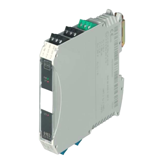
Summary of Contents for Stahl 9163
- Page 1 Typ/Type 9163 Rev B Trennübertrager Eingang Isolating Repeater Input Betriebsanleitung Operating Instructions...
-
Page 2: Table Of Contents
Inhaltsverzeichnis Allgemeine Angaben ....................3 Hersteller ......................3 Angaben zu Betriebsanleitung ................3 Verwendete Symbole ....................3 Sicherheitshinweise ....................3 Normenkonformität...................... 4 Funktion ........................4 Kennzeichnung und technische Daten ................ 5 Geräteaufbau ......................6 Projektierung ....................... 6 Maximal zulässige Umgebungstemperaturen ............6 Anordnung und Montage ..................... -
Page 3: Allgemeine Angaben
Bei Errichtung und Betrieb ist Folgendes zu beachten: • Es gelten die nationalen Montage- und Errichtungsvorschriften (z.B. IEC/EN 60079-14) • Bei SIL Anwendungen FMEDA Report SIL STAHL 08/10-21 R015. • Das Gerät ist in Zone 2, Zone 22 oder außerhalb explosionsgefährdeter Bereiche zu installieren. -
Page 4: Normenkonformität
Das Gerät darf nur in unbeschädigtem, trockenem und sauberem Zustand eingebaut und betrieben werden. Sollten Sie Fragen bezüglich der richtigen Handhabung des Gerätes haben, wenden Sie sich bitte an R. STAHL Schaltgeräte GmbH, Am Bahnhof 30, 74638 Waldenburg, Germany, Telefon +49-7942-943-0 wenden oder an eine unserer Niederlassungen, siehe www.stahl-ex.com. -
Page 5: Kennzeichnung Und Technische Daten
-40...+60 °C / +70 ° C Lagertemperatur -40...+80 °C relative Feuchte (keine Betauung) < 95 % Weitere technische Daten sind dem aktuellen Datenblatt zu entnehmen. Bei anderen vom Standard abweichenden Betriebsbedingungen nehmen Sie bitte Rücksprache mit dem Hersteller. Trennübertrager Eingang Typ 9163... -
Page 6: Geräteaufbau
Geräte können durch unzulässig hohe Umgebungstemperaturen ausfallen. • Es erlischt die Herstellerhaftung und Gewährleistung. Der Schaltschrank muss in einer Art aufgebaut sein, der es erlaubt das Gerät im spezifizierten Temperaturbereich zu betreiben. Das Dokument ist verfügbar unter: www.stahl.de. Anordnung und Montage 9.1 Maßzeichnung Maß X Schraubklemmen... -
Page 7: Installation
Das Gerät ist in der Zone 2, 22 oder außerhalb explosionsgefährdeter Bereiche zu installieren. Bei Betrieb in Zone 2, 22 ist das Gerät in ein Gehäuse einzubauen, das den Anforderungen der EN 60079-15 genügt (z.B. in ein Gehäuse Typ 8146 der Firma R. STAHL Schaltgeräte GmbH). Montage und Demontage 9.3.1. - Page 8 Gehäuses muss dabei auf die Außenkante des pac-Trägers gesetzt werden. Danach das Gerät einschwenken bis roter Rasthebel einrastet. Der rote Rasthebel muss eingerastet sein. Demontage Rasthebel (1) mit einem Schraubendreher ausschwenken. Gerät wird aus dem Steckplatz geschoben (2). Trennübertrager Eingang Typ 9163...
-
Page 9: Inbetriebnahme
10 Inbetriebnahme 10.1 Anschlüsse Typen 9163/*3-11-10 Typ 9163/11-81-10 Anschluss der Speisung (grüne Klemme 9-/7+): Art der Versorgung Anschluß Direkte Versorgung des Mess- Grüne Klemme mit den Anschlüssen 9- und 7+ umformerspeisegerätes Versorgung über pac-Bus Siehe Kapitel 9.3.1 Trennübertrager Eingang Typ 9163... -
Page 10: Einstellungen
Das Gerät verfügt über keine Einstellmöglichkeiten. 11 Betrieb- und Betriebszustände Bevor Sie das Gerät in Betrieb nehmen, stellen Sie sicher, dass • das Gerät vorschriftsmäßig installiert wurde • das Gerät nicht beschädigt ist • die Kabel ordnungsgemäß angeschlossen sind Trennübertrager Eingang Typ 9163... -
Page 11: Reparatur Und Instandhaltung
Betriebsanleitung 12 Reparatur und Instandhaltung Reparaturen an den Geräten dürfen ausschließlich durch R. STAHL ausgeführt werden. Die Geräte sind wartungsfrei. Fehlersuchplan: Fehlererkennung Fehlerursache Fehlerbehebung LED „PWR“ erloschen Hilfsenergie ausgefallen oder Hilfsenergieversorgung kontrollieren. Gerätesicherung defekt Bei defekter Sicherung das Gerät zur Reparatur geben. -
Page 12: General Information
• The national installation and assembly regulations (e.g. IEC/EN 60079-14) apply. • For SIL applications please observe the FMEDA report “SIL STAHL 08/10-21 R015”. • The apparatus may be installed in Zone 2, Zone 22 or outside the explosion hazard areas. -
Page 13: Conformity To Standards
Should there be any question about the correct handling of the module, please contact R. STAHL Schaltgeräte GmbH, Am Bahnhof 30, 74638 Waldenburg, Germany, telephone +49-7942-943-0, or contact one of our offices or representatives see www.stahl-ex.com. Conformity to standards The information about the conformity to standards can be found in the manufacturer’s declaration of conformity in the appendix of this document. -
Page 14: Marking And Technical Data
-40...+80 °C Relative humidity (no condensation) < 95 % Additional technical data can be found in the current data sheet. Please consult with the manufacturer before operating under conditions which deviate from the standard operating conditions. Isolating Repeater Input Type 9163... -
Page 15: Device Description
The manufacturer’s liability and warranty expire. The cabinet need to be built in a way which allows to operate the device within the specified temperature range The cabinet installation guide is available on www.stahl-ex.com. Arrangement and fitting 9.1 Dimensions Size X... -
Page 16: Mounting And Dismounting
DIN rail. Swivel the device until it is snapped on the DIN rail. Dismounting Pull the latch (1) with the screw driver out. Swivel the device out. Isolating Repeater Input Type 9163... - Page 17 All devices are equipped with detachable terminals. Dismounting Place the screw driver between terminal and enclosure. Move the screw driver as described. Mounting Place the terminal into the terminal slot and press it towards the device until it is locked. Isolating Repeater Input Type 9163...
-
Page 18: Commissioning
Types 9163/*3-11-10 Type 9163/11-81-10 Note for types 9163/*3-**-**: A working HART communication requires a minimum load resistance (e.g. input resistance of input card) of 250 Ω in the output circuit. Is this not available the internal 221 Ω resistance can be used. Then the connection has to be done on terminals 3+/2- or 4+/6-. -
Page 19: Settings
0..5 V 0..10 V Channel 1 10 + 12 + 10 + Output connections (black terminals PIN 1,2,3 and 4,5,6) 9163/**-11-10 9163/*3-10-10 Channel 2 Channel 1 10.2 Settings The device does not require a setting. Isolating Repeater Input Type 9163... -
Page 20: Operation And Operational States
• the cables are properly connected 12 Maintenance and repair It is recommended that all repairs to our devices be carried out by R. STAHL. In exceptional cases, repair may be performed by approved third-parties. The devices are maintenance-free. Troubleshooting chart:... - Page 24 R. STAHL Schaltgeräte GmbH Am Bahnhof 30 74638 Waldenburg (Württ.) – Germany www.stahl.de ID-Nr. 9163611310 / 221792 S-BA-9163-004-de/en-03/2014...


Need help?
Do you have a question about the 9163 and is the answer not in the manual?
Questions and answers