
Related Manuals for Stahl ispac 9186/12


Summary of Contents for Stahl ispac 9186/12
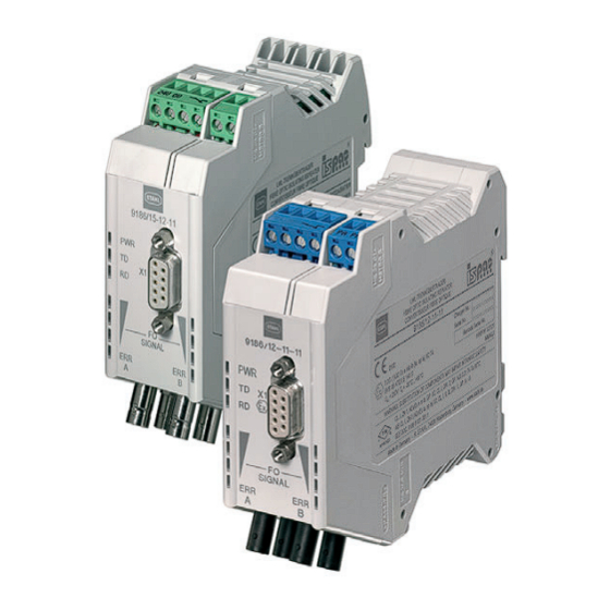
- Page 1 Manual Additional languages www.stahl-ex.com Fibre optic isolating repeater Series 9186...
-
Page 2: Table Of Contents
Contents General Information ....................3 Manufacturer .......................3 Information about the Manual ................3 Further Documents .....................3 Conformity with Standards and Regulations ............3 Explanation of the Symbols ................4 Symbols used in this Manual ................4 Warning Notes ....................4 Symbols on the Device ..................5 Safety Notes .......................5 Storage of the Manual ..................5 Personnel Qualification ..................5 Safe Use ......................6... -
Page 3: General Information
• Product information 9186 For further languages, see www.stahl-ex.com. Conformity with Standards and Regulations See certificates and EU Declaration of Conformity: www.stahl-ex.com. The device has IECEx approval. See IECEx homepage: http://iecex.iec.ch/ Further national certificates can be downloaded via the following link: http://www.r-stahl.com/downloads/certificates.html. -
Page 4: Explanation Of The Symbols
Explanation of the Symbols Explanation of the Symbols Symbols used in this Manual Symbol Meaning Tips and recommendations on the use of the device General danger Danger due to explosive atmosphere Danger due to laser radiation Warning Notes Warnings must be observed under all circumstances, in order to minimize the risk due to construction and operation. -
Page 5: Symbols On The Device
Specialists who perform these tasks must have a level of knowledge that meets applicable national standards and regulations. Additional knowledge is required for tasks in hazardous areas! R. STAHL recommends having a level of knowledge equal to that described in the following standards: •... -
Page 6: En 3.3 Safe Use
• Ensure that the contents of this manual are fully understood by the personnel in charge. • Always consult with R. STAHL Schaltgeräte GmbH if using the device under operating conditions which are not covered by the technical data. • We are not liable for damage caused by incorrect or unauthorised use of the device or by non-compliance with this manual. -
Page 7: En Modifications And Alterations
Safety Notes Additionally for Type 9186/.5 • Install the device in Zones 2, 22 or outside of hazardous areas. • When used in Zones 2 or 22, the device must be built into an enclosure which corresponds to the requirements of IEC/EN 60079-15 or IEC/EN 60079-31. •... -
Page 8: Function And Device Design
Function and Device Design Function and Device Design DANGER Explosion hazard due to improper use! Non-compliance results in severe or fatal injuries. • The device may only be used according to the operating conditions described in this manual. • Use the device only for the intended purpose specified in this manual. -
Page 9: Device Design
Function and Device Design Device Design Type 9186/12 Device component Description Screw terminals 1 2 3 4 21 22 Terminal not used Terminals 3 + 4 Fault message contact 21,22 Terminals 5 + 6 Shield connection (equipotential bonding) RS-485 interface Sub-D, RS-485 RS-485 interface, data line Supply voltage status, RS-485... - Page 10 Function and Device Design Type 9186/.5 Device component Description Screw terminals 1 2 3 4 Terminal +24 V auxiliary power connection Terminal 0 V auxiliary power connection Terminals 3 + 4 Fault message contact RS-485 interface Sub-D, RS-485 RS-485 interface, data line Supply voltage status, RS-485 Green LED Indication for supply voltage...
-
Page 11: En En
Technical Data Technical Data Marking Type designation 9186/..-1.-11 CE marking 0158 Explosion Protection Version 9186/12-11-11 9186/.5-12-11 Global (IECEx) Gas and dust IECEx BVS 12.0081X IECEx BVS 13.0107X Ex e mb ib [ia op is Ga] IIC T4 Gb Ex nA nC [op is T6 Ga] IIC T4 Gc [Ex ia Da] IIIC [Ex op is Da] IIIC Europe (ATEX) - Page 12 Technical Data Explosion Protection Ex i fault-contact Max. permissible 24 V – voltage U Max. permissible 600 mA – current I Internal capacity negligible – and inductivity Optical interface Type of protection Ex op is IIC T6 Radiant power P 15 mW Technical Data Version...
- Page 13 G 62.5 / 125 multi mode Integrated diagnosis function with alarm and automatic switching to the backup path. This enables increased availability. Electrical interfaces Protocols PROFIBUS DP, Modbus, HART over RS-485, ServiceBus R. STAHL (IS1+) Version RS-485-IS (PNO) RS-485 Connection...
- Page 14 Technical Data Technical Data Fault control Power supply Fault-contact is open failure Transmission LED green and yellow "FO signal", fault-contact is closed level is good Transmission LED yellow "FO signal", fault-contact is open level reduced (-1,5 dBm) Fibre breakage or LED red "FO ERR", fault-contact is open transmission level is too low (-3 dBm)
-
Page 15: Engineering
RS-485 05354E00 9186/25-..-.. RS-485 06005E00 For further technical data, see www.stahl-ex.com. Engineering DANGER Explosion hazard due to too high temperature in the cabinet! Non-compliance results in severe or fatal injuries! • Install and adjust the cabinet in such a way that it is always operated within the permissible temperature range. -
Page 16: Profibus
Engineering PROFIBUS The data transmission lines and network components may cause signal delays. The bus parameters must therefore by adjusted using appropriate project engineering software. The defined maximum network reach must also be taken into account. Operating in linear structure Calculate the minimum slot time T according to the rule SL min... - Page 17 Engineering • Values a and b are dependent upon the data rate and bus profile used (see table). Adjust the slot time T of the system configuration accordingly. • Raise the RETRY LIMIT parameter by at least three. • Confirm that the minimum protocol processing time MIN T amounts to at least 11 bit times (MIN T ) 11).
-
Page 18: En 6.2 Modbus / Servicebus
Engineering • Note the maximum ring reach, which depends upon the data rate and number of devices in use according to the table. Example: • Number of FO converters in the ring: 6 • Speed: 500 kbps • Permitted total reach: 14.4 km •... - Page 19 Engineering Modbus For Modbus and similar UART protocols: At a minimum frame length of 44 bits, the maximum FO ring size is determined based on the number of devices and the data rate. Table: FO ring size in Modbus operating mode (various data rates) Num- Data rate (kbps) of the FO ring size [km] ber of...
-
Page 20: En 6.3 Profisafe
Engineering ServiceBus The number of devices is limited to a maximum of 24 when operating in ServiceBus mode. Table: Ring size in ServiceBus operating mode (9.6 kbps data rate) Number of devices Ring size [km] Not permitted 9.90 13.20 19.80 26.40 33.00 39.60... -
Page 21: Transport And Storage
Transport and Storage Transport and Storage • Transport and store the device only in the original packaging. • Store the device in a dry place (no condensation) and vibration-free. • Do not drop the device. Mounting and Installation The type 9186/12 device is approved for use in gas explosion hazardous areas of Zones 1 and 2 and dust explosion hazardous areas of Zones 21 and 22 and in safe areas. -
Page 22: Dimensions / Fastening Dimensions
Mounting and Installation Dimensions / Fastening Dimensions Dimensional drawings (all dimensions in mm [inches]) – Subject to modifications 99 3.89 99 3 89 35,20 35,20 106 4.17 106 4 17 1.38 1 38 11335E00 06251E00 9186/12-11-11 9186/15-12-11 99 3.89 35,20 106 4.17 1.38 11328E00... -
Page 23: Mounting / Dismounting, Operating Position
Mounting and Installation Mounting / Dismounting, Operating Position 8.2.1 Mounting / Dismounting on Top Hat Rail • Connect the mounting rails to the protective ground using an earthing terminal so that the module is earthed when attached to the mounting rail. Mounting •... -
Page 24: En En
Mounting and Installation Installation Operation under difficult conditions, such as, in particular, on ships, requires additional measures to be taken for correct installation, depending on the place of use. Further information and instructions on this can be obtained from your regional sales contact on request. 8.3.1 Opening and closing the Enclosure for Parameterisation Opening the enclosure •... - Page 25 Mounting and Installation 8.3.2 Electrical Connections DANGER Explosion hazard caused by too high voltage! Non-compliance results in severe or fatal injuries. • Connect the device only to equipment with internal voltage : max. 253 V AC / 50 Hz. • Connect the device only to intrinsically safe terminals. DANGER Explosion hazard due to incorrect safety characteristic values of the device or connected field devices!
- Page 26 Mounting and Installation Preparing the supply / auxiliary power connection for type 9186/12-11-11 • Use suitable tools to strip the cable for connecting the auxiliary power. • Place the insulating core end sleeve onto the stripped core and secure it. •...
- Page 27 8.3.5 Connection of the RS-485 Data Line The fibre optic isolating repeater is designed to be connected to a RS-485-IS interface. Connection to a RS-485 Ex i according to R. Stahl specification is not intended. DANGER Explosion hazard due to use of unapproved components! Non-compliance results in severe or fatal injuries.
- Page 28 Mounting and Installation 8.3.7 Fault Message Contact Connection The fibre optic isolating repeaters are equipped with a potential-free switching contact used as the NC for error diagnosis (connection terminals 3 and 4, see chapter "Device design"). This contact opens on the respective module if: •...
-
Page 29: Parameterization And Commissioning
Parameterization and Commissioning Coupling the FO isolating repeater • Take note of the fibre optic signal direction. • Connect the "TD" connection (transmitter) of module 1 to the "RD" connection (receiver) of module 2. • Connect the "TD" connection (transmitter) of module 1 to the "RD"... -
Page 30: En 9.2 Parameterizations
A special setting for DIP switches 1 to 4 is set for R. STAHL ServiceBus. It makes operation of up to 24 isolating repeaters possible in the ring. If the R. STAHL ServiceBus protocol is used without this setting, the number of type 9186 isolating repeaters that can be connected to the ring structure is reduced to 12. - Page 31 Parameterization and Commissioning Transfer rate in DIP switches (1 to 4) kbps 1500 187.5 93.75 57.6 45.45 38.4 19.2 AUTO *) Reserved ServiceBus 9k6 Setting the remaining functions (DIP switches 5 to 10) DIP switches 11 BIT ECHO ON INVERS REDUN- PORT B ON PROFIBUS...
- Page 32 Parameterization and Commissioning Position Function Designation Note switch 11 bit character length 11 BIT Transmission protocol with 11 bit character length. Only applicable if DIP switch 10 is on RS-485 10 bit character length 10 BIT Transmission protocol with 10 bit character length.
-
Page 33: Operation
Check the wiring of the auxiliary power supply. If the error cannot be eliminated using the mentioned procedures: • Contact R. STAHL Schaltgeräte GmbH. For fast processing, have the following information ready: • Type and serial number of the device •... -
Page 34: Maintenance And Repair
• Only return or package the devices after consulting R. STAHL! Contact the responsible representative at R. STAHL for this. R. STAHL's customer service is available to handle returns if repair or service is required. Only return or package the devices after contacting and consulting R. STAHL! -
Page 35: Cleaning
You will receive an RMA slip after speaking with customer service. • Send the device along with the RMA slip in the packaging to R. STAHL Schaltgeräte GmbH (refer to Section 1.1 for the address). Cleaning • To avoid electrostatic charging, the devices located in potentially explosive areas may only be cleaned using a damp cloth.
Need help?
Do you have a question about the ispac 9186/12 and is the answer not in the manual?
Questions and answers