
Related Manuals for Stahl ISpac 9165


Summary of Contents for Stahl ISpac 9165
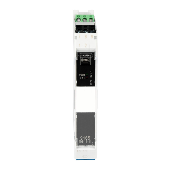
- Page 1 Typ/Type 9165 Trennübertrager Ausgang Isolating Repeater Output Betriebsanleitung Operating Instructions...
-
Page 2: Table Of Contents
Inhaltsverzeichnis Allgemeine Angaben ..................3 Hersteller ......................3 Angaben zu Betriebsanleitung ................3 Verwendete Symbole ................... 3 Sicherheitshinweise ..................3 Normenkonformität ..................4 Funktion ......................4 Kennzeichnung und technische Daten ............5 Geräteaufbau ....................6 Projektierung ....................6 Anordnung und Montage ................6 Maßzeichnung ..................... -
Page 3: Allgemeine Angaben
Kenntnis der geltenden Vorschriften und Bestimmungen. Bei Errichtung und Betrieb ist Folgendes zu beachten: • Bei SIL Anwendungen FMEDA Report SIL STAHL 04/04-03 R004 beachten. • Das Gerät ist in Zone 2, Zone 22 oder außerhalb explosionsgefährdeter Bereiche zu installieren. -
Page 4: Normenkonformität
Das Gerät darf nur in unbeschädigtem, trockenem und sauberem Zustand eingebaut und betrieben werden. Sollten Sie Fragen bezüglich der richtigen Handhabung des Gerätes haben, wenden Sie sich bitte an R. STAHL Schaltgeräte GmbH, Am Bahnhof 30, 74638 Waldenburg, Germany, Telefon +49-7942-943-0 wenden oder an eine unserer Niederlassungen, siehe www.stahl-ex.com. -
Page 5: Kennzeichnung Und Technische Daten
deutsch Betriebsanleitung Kennzeichnung und technische Daten Typbezeichnung 9165/ab-11-1f (a:1,2 b:1,6 f:0,1) CE-Kennzeichnung 0158 II 3 (1) G Ex nA nC [ia Ga] IIC T4 Gc ATEX Kennzeichnung Explosionsschutz II (1) D [Ex ia Da] IIIC DMT 03 ATEX E 012 X Prüfstelle und Bescheinigungsnummer Ex nA nC [ia Ga] IIC T4 Gc IECEx Kennzeichnung Explosionsschutz... -
Page 6: Geräteaufbau
Geräte können durch unzulässig hohe Umgebungstemperaturen ausfallen. • Es erlischt die Herstellerhaftung und Gewährleistung. Der Schaltschrank muss in einer Art aufgebaut sein, der es erlaubt das Gerät im spezifizierten Temperaturbereich zu betreiben. Das Dokument ist verfügbar unter: www.stahl-ex.com. Anordnung und Montage 9.1 Maßzeichnung Maß X Schraubklemmen... -
Page 7: Installation
Bei Betrieb in Zone 2, 22 ist das Gerät in ein Gehäuse einzubauen, das den Anforderungen der EN 60079-15 genügt (z.B. in ein Gehäuse Typ 8146 der Firma R. STAHL Schaltgeräte GmbH). Montage und Demontage 9.3.1 Montage / Demontage pac-Bus Der pac-Bus ist ein Zubehör, das die Verdrahtung der Hilfsenergie und das... - Page 8 Betriebsanleitung deutsch Demontage Fußriegel (1) mit dem Schraubendreher etwas herausziehen. Gerät herausschwenken. 9.3.3 Montage / Demontage auf pac-Träger Montage Schwarze und grüne Klemmen entfernen. Bei einkanaligen Geräten: Abdeckung im Klemmenschacht 2 entfernen (zwischen schwarzer und grüner Klemme) Gerät auf pac-Träger aufsetzen. Die Aussparung des Gehäuses muss dabei auf die Außenkante des pac-Trägers gesetzt werden.
-
Page 9: Inbetriebnahme
deutsch Betriebsanleitung Demontage Schraubendreher hinter Klemme ansetzen. Klemme herausdrücken. Montage Klemme in Gerät stecken, bis Klemme einrastet. 10 Inbetriebnahme 10.1 Anschlüsse LF )* LF )* )* Varianten 9165/16-11-10 und 9165/26-11-10 ohne Leitungsfehlermeldung mittels Relais 10.2 Einstellungen Die nachfolgend beschriebenen Einstellungen können nur bei den Typen 9165/16-11-11 und 9165/26-11-11 vorgenommen werden. -
Page 10: Betrieb- Und Betriebszustände
Gerät vorschriftsmäßig installiert wurde • das Gerät nicht beschädigt ist • die Kabel ordnungsgemäß angeschlossen sind 12 Reparatur und Instandhaltung Reparaturen an den Geräten dürfen ausschließlich durch R. STAHL ausgeführt werden. Die Geräte sind wartungsfrei. Fehlersuchplan: Fehlererkennung Fehlerursache Fehlerbehebung LED „PWR“... -
Page 11: General Information
Operating Instructions General information 1.1 Manufacturer R. STAHL Schaltgeräte GmbH Phone: +49 7942 943-0 Am Bahnhof 30 Fax: +49 7942 943-4333 74638 Waldenburg Internet: www.stahl.de Germany 1.2 Information regarding the operating instruction ID-Nr.: 171456 / 9165612310 Pub-Nr.: S-BA-9165-005-de/en-02/2015 HW-revision Symbols used Danger The device complies with the applicable EC standards. -
Page 12: Conformity To Standards
Should there be any question about the correct handling of the module, please contact R. STAHL Schaltgeräte GmbH, Am Bahnhof 30, 74638 Waldenburg, Germany, telephone +49-7942-943-0, or contact one of our offices or representatives see www.stahl-ex.com. Conformity to standards The information about the conformity to standards can be found in the manufacturer’s declaration of conformity in the appendix of this document. -
Page 13: Function
english Operating Instructions Function The isolating repeaters are used for intrinsically safe operation of control valves, i/p converters or displays. The continued operation of intrinsically safe HART field devices is possible. The devices bidirectionally transfer a superimposed HART communications signal. Marking and technical data Type designation 9165/ab-11-1f (a:1,2 b:1,6 f:0,1) -
Page 14: Device Description
The manufacturer’s liability and warranty expire. The cabinet need to be built in a way which allows to operate the device within the specified temperature range The cabinet installation guide is available on www.stahl-ex.com. Arrangement and fitting 9.1 Dimensions Size X... -
Page 15: Installation
In the case of operation in Zone 2 or Zone 22, the transmitter supply unit must be fitted in an enclosure which complies with the requirements of EN 60079-15 (e.g. in an enclosure type 8146 from the R. STAHL). 9.3 Mounting and dismounting 9.3.1 Mounting of pac-Bus... - Page 16 Operating Instructions english Dismounting Pull the latch (1) with the screw driver out. Swivel the device out. 9.3.3 Mounting / dismounting on pac-Carrier Mounting Dismount the black and the green terminal. (see chapter 9.3.4) Single channel device: Dismount the cover of terminal slot 2. (between black and green terminal) Put the device on the pac-Carrier and swivel the device until the red locking handle is locked.
-
Page 17: Commissioning
english Operating Instructions 9.3.4 Mounting / Dismounting detachable terminals All devices are equipped with detachable terminals. Dismounting Place the screw driver between terminal and enclosure. Move the screw driver as described. Mounting Place the terminal into the terminal slot and press it towards the device until it is locked. 10 Commissioning 10.1 Connections Hazardous... -
Page 18: Operation And Operational States
HART signal feedback. If the procedure described above does not obtain the desired result, please contact your local R.STAHL sales and service representative. In order to quickly process your request, please provide us with the following information: •... -
Page 19: Eg-Konformitätserklärung / Ec-Declaration Of Conformity
english Operating Instructions EG-Konformitätserklärung / EC-Declaration of Conformity Isolating Repeater Output Type 9165... -
Page 20: Control Drawing - Fm
Control drawing - FM... - Page 24 R. STAHL Schaltgeräte GmbH Am Bahnhof 30 74638 Waldenburg (Württ.) – Germany www.stahl.de ID-Nr. 171456 / 9165612310 S-BA-9165-005-de/en-02/2015...
Need help?
Do you have a question about the ISpac 9165 and is the answer not in the manual?
Questions and answers