
Subscribe to Our Youtube Channel
Related Manuals for Stahl 9186 Series


Summary of Contents for Stahl 9186 Series
- Page 1 Manual Additional languages r-stahl.com Fibre optic isolating repeater Series 9186...
-
Page 2: Table Of Contents
Contents Contents General Information .....................3 Manufacturer......................3 Information about this Manual................3 Further Documents ....................3 Conformity with Standards and Regulations............3 Explanation of Symbols ..................4 Symbols used in this Manual ................4 Warning Notes .....................4 Symbols on the Device ..................5 Safety Notes ......................5 Storage of the Manual..................5 Personnel Qualification ..................5 Safe Use ......................6 Modifications and Alterations ................8... -
Page 3: En Fr
• Operating instructions • National information and documents relating to use in hazardous areas (see also chapter 1.4) For documents in other languages, see r-stahl.com. Conformity with Standards and Regulations IECEx, ATEX, EU Declaration of Conformity and further national certificates and documents can be downloaded via the following link: https://r-stahl.com/en/global/support/downloads/... -
Page 4: Explanation Of Symbols
Explanation of Symbols Explanation of Symbols Symbols used in this Manual Symbol Meaning Tips and recommendations on the use of the device General hazard Explosive atmosphere hazard Laser radiation hazard Warning Notes Warning notes must be observed under all circumstances, in order to minimise the risk resulting from design engineering and operation. -
Page 5: Symbols On The Device
Additional knowledge is required for any activity in hazardous areas! R. STAHL recommends having a level of knowledge equal to that described in the following standards: • IEC/EN 60079-14 (Electrical installations design, selection and erection) •... -
Page 6: Safe Use
• Use the device in accordance with its intended and approved purpose only. • Always consult R. STAHL Schaltgeräte GmbH if using the device under operating conditions which are not covered by the technical data. • Make sure that the device is not damaged. - Page 7 Safety Notes Additionally for type 9186/12: • For use in Zone 1 or Zone 2, install the device in a protective enclosure or cabinet that corresponds to a recognised type of protection according to IEC/EN 60079-0 and a degree of protection of at least IP54 according to IEC/EN 60529.
-
Page 8: Modifications And Alterations
• Before commissioning, make sure that the device is not damaged. • Only perform maintenance work described in this manual. • Repair work on the devices must be performed only by R. STAHL Schaltgeräte GmbH. • The device contains components that can be damaged by electrostatic discharge. -
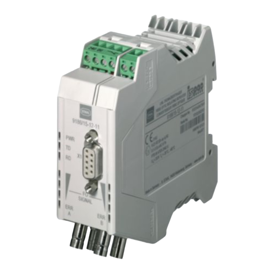
Page 9: Device Design
Function and Device Design Device Design Type 9186/12 Device element Description Screw terminals 1 2 3 4 21 22 1, 2 Terminal Not used 3, 4 Terminals 3 + 4 Fault message contact 21, 22 Terminals 5 + 6 Shield connection (equipotential bonding) RS485 interface Sub-D, RS485 RS485 interface, data line... - Page 10 Function and Device Design Type 9186/.5 Device element Description Screw terminals 1 2 3 4 Terminal +24 V auxiliary power connection Terminal 0 V auxiliary power connection 3, 4 Terminals 3 + 4 Fault message contact RS485 interface Sub-D, RS485 RS485 interface, data line Supply voltage status, RS485 Green LED...
-
Page 11: Technical Data
Technical Data Technical Data Marking Type designation 9186/..-1.-11 CE marking Explosion protection Version 9186/12-11-11 9186/.5-12-11 Global (IECEx) Gas and dust IECEx BVS 12.0081X IECEx BVS 13.0107X Ex e mb ib [ia op is Ga] IIC T4 Gb Ex nA nC [op is T6 Ga] IIC T4 Gc [Ex ia Da] IIIC [Ex op is Da] IIIC Europe (ATEX) - Page 12 Technical Data Technical data Version 9186/12-11-11 9186/.5-12-11 Electrical data Auxiliary power Nominal voltage U 24 V DC Voltage range 18 to 31.2 V Residual ripple < 3.6 V Nominal current 67 mA 130 mA (at U Power consumption ≤ 2 W Operation indication Green "PWR"...
- Page 13 Technical Data Technical data Version 9186/12-11-11 9186/.5-12-11 Electrical interfaces Protocols PROFIBUS DP, Modbus, HART over RS485, R. STAHL ServiceBus (IS1+) Version RS485-IS (PNO) RS485 Connection Sub-D socket X1, 9-pin Transmission rate 1.2 kbps to 1.5 Mbps 9.6 kbps to 1.5 Mbps...
- Page 14 Technical Data Technical data Version 9186/12-11-11 9186/.5-12-11 Mechanical data Connection technology Auxiliary power Spring clamp terminal, 0.2 to 1.5 mm Screw terminal, 0.2 to 2.5 mm Green (Ex e) Fault message Screw terminal, 0.2 to 2.5 mm Blue Screw terminal, 0.2 to 2.5 mm Green contact (Ex i)
- Page 15 9186/.5-12-11 Mounting/installation Installation conditions Mounting type On DIN rail (NS 35/15; NS 35/7.5) Connection diagram 9186/12-..-.. RS485-IS ISP+ ISGND 05352E00 9186/15-..-.. RS485 05354E00 9186/25-..-.. RS485 06005E00 For further technical data, see r-stahl.com. 918660330020 Fibre optic isolating repeater 2023-10-20·HB00·III·en·02 Series 9186...
-
Page 16: Project Engineering
Project Engineering Project Engineering NOTICE An ambient temperature that is too high may cause failure of the devices installed in the cabinet. Non-compliance can result in material damage. • Install and set up the cabinet in such a way that all devices installed within it are always operated within their permissible temperature range. -
Page 17: Profibus
Project Engineering PROFIBUS The data transmission lines and network components may cause signal delays. The bus parameters must therefore be adjusted using appropriate project engineering software. The defined maximum network reach must also be taken into account. Operation in a linear structure Calculate the min. - Page 18 Project Engineering Operation in a redundant ring A ring structure is made up of at least three type 9186 devices. Calculate the min. slot time T according to the following formula slot_Init = a + b x L + 44 x N slot_Init where: : Min.
-
Page 19: Modbus/Servicebus
Project Engineering Modbus/ServiceBus Data transmission lines and network components may cause signal delays. If necessary, these must be taken into account when configuring the TIMEOUT times of the bus system used. Calculate the signal delay dT according to the following formula dT= b x L + 2 x N where: Signal delay in bit times for a complete signal cycle... - Page 20 Project Engineering Modbus For Modbus and similar UART protocols: At a minimum frame length of 44 bits, the maximum FO ring size is determined based on the number of devices and the transmission rate. Table: FO ring size in Modbus operating mode (various data rates) Number Data rate [kBps] of the FO ring size [km] 19.2...
- Page 21 Project Engineering ServiceBus The number of devices is limited to a maximum of 24 when operating in ServiceBus mode. Table: Ring size in ServiceBus operating mode (9.6 kBps data rate) Number of devices Ring size [km] Not permissible 9.90 13.20 19.80 26.40 33.00...
-
Page 22: Transport And Storage
Transport and Storage Transport and Storage • Transport and store the device only in the original packaging. • Store the device in a dry place (no condensation) free of vibrations. • Do not drop the device. Mounting and Installation Type 9186/12 devices are approved for use in gas hazardous areas of Zones 1 and 2 and in safe areas. -
Page 23: Dimensions/Fastening Dimensions
Mounting and Installation Dimensions/Fastening Dimensions Dimensional drawings (all dimensions in mm [inch]) – Subject to change 99 3 89 99 3 89 35 20 35,20 106 4 17 106 4 17 1 38 1 38 11335E00 06251E00 9186/12-11-11 9186/15-12-11 99 3.89 35 20 106 4.17 1.38... -
Page 24: Mounting/Dismounting, Operating Position
Mounting and Installation Mounting/Dismounting, Operating Position 8.2.1 Mounting/Dismounting on DIN Rail • Connect the mounting rail to the protective earth using an earthing terminal so that the module is earthed when attached to the mounting rail. Mounting on DIN rail •... -
Page 25: Installation
Mounting and Installation Installation Operation under difficult conditions, e.g. on ships in particular, requires additional measures to be taken for correct installation, depending on the operating location. Further information and instructions on this can be obtained on request from your designated sales contact. 8.3.1 Opening and closing the Enclosure for Parameterisation Opening the enclosure •... - Page 26 Mounting and Installation 8.3.2 Electrical Connections DANGER Explosion hazard due to excessive voltage! Non-compliance results in severe or fatal injuries. • Only connect the device to equipment with internal voltage : Max. 253 V AC/50 Hz. DANGER Explosion hazard due to incorrect safety characteristic values of the device or connected field devices! Non-compliance results in severe or fatal injuries.
- Page 27 Mounting and Installation Preparing the power supply/auxiliary power connection for type 9186/12-11-11 • Use suitable tools to strip the cable for connecting the auxiliary power. • Place the insulating core end sleeve onto the stripped core and secure it. • Prepare the power supply cable with insulating core end sleeve.
- Page 28 PROFIBUS segment. Learn more details about project engineering in the operating instructions entitled "Project engineering, installation and commissioning of the RS485 fieldbus system from R. STAHL for safe and hazardous areas". Data rate and range for RS485-IS interface Data rate Range for twisted pair cable, dia.
- Page 29 Mounting and Installation 8.3.7 Fault Message Contact Connection The fibre optic isolating repeaters are equipped with a potential-free switching contact which is used as an NC contact for error diagnosis (connection terminals 3 and 4, see chapter 4.2). This contact opens on the relevant module if: •...
-
Page 30: Parameterisation And Commissioning
Parameterisation and Commissioning Coupling the fibre optic isolating repeater • Take note of the fibre optic cable's signal direction. • Connect the "TD" connection (transmitter) of module 1 to the "RD" connection (receiver) of module 2. • Connect the "RD" connection (receiver) of module 1 to the "TD"... -
Page 31: Parameterisation
For R. STAHL ServiceBus, there is a special setting for DIP switches 1 to 4. This makes it possible to operating up to 24 9186 isolating repeaters in a ring. - Page 32 Parameterisation and Commissioning Transfer rate DIP switch (1 to 4) [kBps] 1500 187.5 93.75 57.6 45.45 38.4 19.2 AUTO Reserved ServiceBus 9k6 The "AUTO" switch position only applies to PROFIBUS Setting the remaining functions (DIP switches 5 to 10) DIP switch (5 to 10) 11 BIT ECHO ON INVERSE...
- Page 33 Parameterisation and Commissioning Position Function Designation Note switch 11 bit character length 11 BIT Transmission protocol with 11 bit character length. Only applicable if DIP switch 10 is set to RS485 10 bit character length 10 BIT Transmission protocol with 10 bit character length.
-
Page 34: Operation
Operation Operation 10.1 Operation When a line fault is detected, the output signal is identical to the input signal. 10.2 Indicators The corresponding LEDs on the device indicate the operating state of the device (see also the "Function and device design" chapter). Colour "ON"... -
Page 35: Troubleshooting
Check the wiring of the auxiliary power supply. If the error cannot be eliminated using the specified procedures: • Contact R. STAHL Schaltgeräte GmbH. For rapid processing, have the following information ready: • Type and serial number of the device •... -
Page 36: Repair
• Only return or package the devices after consulting R. STAHL! Contact the responsible representative from R. STAHL. R. STAHL's customer service is available to handle returns if repair or service is required. • Contact customer service personally. • Go to the r-stahl.com website. -
Page 37: Accessories And Spare Parts
Malfunction or damage to the device due to the use of non-original components. Non-compliance may lead to material damage. • Use only original accessories and spare parts from R. STAHL Schaltgeräte GmbH. For accessories and spare parts, see the data sheet on our homepage r-stahl.com.
Need help?
Do you have a question about the 9186 Series and is the answer not in the manual?
Questions and answers