Chapters
Table of Contents

Subscribe to Our Youtube Channel
Related Manuals for Stahl ISpac 9170/21-30-10


Summary of Contents for Stahl ISpac 9170/21-30-10
- Page 1 Betriebsanleitung Additional languages r-stahl.com Schaltverstärker – Ableitüberwachung Typ 9170/21-30-10...
-
Page 2: Table Of Contents
Inhaltsverzeichnis Allgemeine Angaben ...................3 Hersteller ......................3 Zu dieser Betriebsanleitung ................3 Weitere Dokumente ....................3 Konformität zu Normen und Bestimmungen ............3 Erläuterung der Symbole ..................4 Symbole in der Betriebsanleitung ...............4 Symbole am Gerät ....................4 Sicherheit ......................5 Bestimmungsgemäße Verwendung ..............5 Qualifikation des Personals ................5 Restrisiken ......................6 Transport und Lagerung ..................7 Produktauswahl und Projektierung ..............8... -
Page 3: De De
Betriebsanleitung während der Lebensdauer des Geräts aufbewahren. Betriebsanleitung dem Bedien- und Wartungspersonal jederzeit zugänglich machen. Betriebsanleitung an jeden folgenden Besitzer oder Benutzer des Geräts weitergeben. Betriebsanleitung bei jeder von R. STAHL erhaltenen Ergänzung aktualisieren. ID-Nr.: 202806 / 9170614310 Publikationsnummer: 2020-08-31·BA00·III·de·03... -
Page 4: Erläuterung Der Symbole
Erläuterung der Symbole Erläuterung der Symbole Symbole in der Betriebsanleitung Symbol Bedeutung Hinweis zum leichteren Arbeiten GEFAHR! Gefahrensituation, die bei Nichtbeachtung der Sicherheitsmaßnahmen zum Tod oder zu schweren Verletzungen mit bleibenden Schäden führen kann. WARNUNG! Gefahrensituation, die bei Nichtbeachtung der Sicherheitsmaßnahmen zu schweren Verletzungen führen kann. -
Page 5: Sicherheit
Bereich zugelassen. Zur bestimmungsgemäßen Verwendung gehört die Beachtung dieser Betriebsanleitung, und der mitgeltenden Dokumente, z.B. des Datenblatts. Alle anderen Anwendungen sind nur nach Freigabe der Firma R. STAHL bestimmungsgemäß. Qualifikation des Personals Für die in dieser Betriebsanleitung beschriebenen Tätigkeiten ist eine entsprechend qualifizierte Fachkraft erforderlich. -
Page 6: 3.3 Restrisiken
Umgebungsbedingungen (siehe Kapitel "Technische Daten") berücksichtigen. Gerät nicht belasten. Verpackung und Gerät auf Beschädigung prüfen. Beschädigungen umgehend an R. STAHL melden. Beschädigtes Gerät nicht in Betrieb nehmen. Gerät in Originalverpackung, trocken (keine Betauung), in stabiler Lage und sicher vor Erschütterungen lagern. -
Page 7: Transport Und Lagerung
Transport und Lagerung Unsachgemäße Montage, Installation, Inbetriebnahme, Instandhaltung oder Reinigung Grundlegende Arbeiten wie Installation, Inbetriebnahme, Instandhaltung oder Reinigung des Geräts dürfen nur nach gültigen nationalen Bestimmungen des Einsatzlandes und von qualifizierten Personen durchgeführt werden. Ansonsten kann der Explosionsschutz aufgehoben werden. Explosionen mit tödlichen oder schweren Verletzungen von Personen können die Folge sein. -
Page 8: Produktauswahl Und Projektierung
Produktauswahl und Projektierung Produktauswahl und Projektierung Schaltschrank so aufbauen und einrichten, dass alle darin installierten Geräte immer innerhalb ihres zulässigen Temperaturbereichs betrieben werden (siehe Installationsanleitung Schaltschrank). HINWEIS! Fehlfunktion oder Geräteschaden bei unsachgemäßer Beschaltung. Nichtbeachten kann zu Sachschäden führen. Beim Einsatz des Gerätes für die temporäre elektrostatische Erdung Eingänge (Klemme 10, 11 bzw. - Page 9 Montage und Installation 6.1.3 Montage / Demontage von Gerät auf Hutschiene und pac-Bus Montage auf Hutschiene 06886E00 Gerät an die Hutschiene ansetzen. Dabei die Aussparung des Gehäuses auf die Außenkante der Hutschiene setzen. Gerät auf Hutschiene aufrasten. Beim Aufschwenken des Geräts auf die Hutschiene darauf achten, dass es nicht verkantet.
-
Page 10: 6.2 Installation
Montage und Installation 6.1.4 Montage / Demontage steckbare Klemmen Alle Geräte sind mit steckbaren Klemmen ausgestattet. Montage Klemme in Gerät stecken, bis Klemme einrastet. Demontage 10859E00 Schraubendreher hinter Klemme ansetzen. Klemme herausdrücken. Installation Bei Betrieb unter erschwerten Bedingungen wie insbesondere auf Schiffen sind zusätzliche Maßnahmen zur korrekten Installation je nach Einsatzort zu treffen. - Page 11 Montage und Installation 6.2.2 Anschlussbilder Anwendung für temporäre elektrostatische Erdung Zone 2 9170/21-30-10 Division 2 Zone 1 Division 1 20534E00 Legende = Schaltverstärker – Ableitüberwachung 9170 = Anschluss der Speisung (24 V DC) = Ausgangssignal des potentialfreien Hilfskontaktes vom Kanal 1 = Ausgangssignal des potentialfreien Hilfskontaktes vom Kanal 2 = Ex i Eingangssignal vom Kanal 1 = Ex i Eingangssignal vom Kanal 2...
- Page 12 Montage und Installation Anwendung für dauerhafte elektrostatische Erdung Zone 2 9170/21-30-10 Division 2 Zone 1 Division 1 20535E00 Legende = Schaltverstärker – Ableitüberwachung 9170 = Anschluss der Speisung (24 V DC) = Ausgangssignal des potentialfreien Hilfskontaktes vom Kanal 1 = Ausgangssignal des potentialfreien Hilfskontaktes vom Kanal 2 = Ex i Eingangssignal vom Kanal 1 = Ex i Eingangssignal vom Kanal 2 = PA-Schiene der Verladeplattform (Anlagenerde)
-
Page 13: Parametrierung Und Inbetriebnahme
Parametrierung und Inbetriebnahme 6.2.4 Anschluss der Erdungsüberwachungsklemme 9170/21-30-10 9191 9191 20533E00 • Darauf achten, dass nur die beschrifteten Klemmstellen der Erdungsüberwachungsklemme kontaktiert werden. 6.2.5 Beschaltung bei induktiven Lasten am Ausgang Schaltbild 15530E Induktive Lasten mit einer Freilaufdiode beschalten. KEINE Beschaltung mit Varistor vornehmen. Parametrierung und Inbetriebnahme GEFAHR! Explosionsgefahr durch Bedienung der DIP-Schalter in der Zone 2 unter Spannung! -
Page 14: 8 Betrieb
Betrieb Betrieb Betrieb Funktionsweise Die z.B. während der Be- und Entladung von Behältern entstehende elektrostatische Aufladung wird abgeleitet und der Stromkreis während des gesamten Betriebs überwacht. Die Überwachung basiert auf der Auswertung des Übergangswiderstandes des Potentialausgleichs - ausgehend vom Schaltverstärker - Ableitüberwachung 9170 über das zu erdende Objekt, die Anschlüsse an der PA-Schiene und zurück zum Schaltverstärker - Ableitüberwachung 9170. -
Page 15: Instandhaltung, Wartung, Reparatur
Reparaturen am Gerät nur durch R. STAHL durchführen lassen. Rücksendung Rücksendung bzw. Verpackung der Geräte nur in Absprache mit R. STAHL durchführen! Dazu mit der zuständigen Vertretung von R. STAHL Kontakt aufnehmen. Für die Rücksendung im Reparatur- bzw. Servicefall steht der Kundenservice von R. STAHL zur Verfügung. -
Page 16: 11 Reinigung
Zubehör und Ersatzteile HINWEIS! Fehlfunktion oder Geräteschaden durch den Einsatz nicht originaler Bauteile. Nichtbeachten kann zu Sachschäden führen. Nur Original-Zubehör und Original-Ersatzteile der R. STAHL Schaltgeräte GmbH (siehe Datenblatt) verwenden. Schaltverstärker – Ableitüberwachung 202806 / 9170614310 Typ 9170/21-30-10... -
Page 17: Anhang A
Anhang A Anhang A 14.1 Technische Daten Kennzeichnung Typbezeichnung 9170/21-30-10 CE-Kennzeichnung 0158 Explosionsschutz Global (IECEx) Gas und Staub IECEx BVS 09.0041X Ex nA nC [ia Ga] IIC T4 Gc [Ex ia Da] IIIC Europa (ATEX) Gas und Staub DMT 02 ATEX E 195 X E II 3 (1) G Ex nA nC [ia Ga] IIC T4 Gc E II (1) D [Ex ia Da] IIIC Bescheinigungen und Zertifikate... - Page 18 Anhang A Technische Daten Elektrische Daten Anzahl der Kanäle Hilfsenergie Nennspannung U 24 V DC Spannungsbereich 18 ... 31,2 V Restwelligkeit innerhalb ( 3,6 V des Spannungsbereichs Nennstrom 50 mA Leistungsaufnahme 1,2 W Max. Verlustleistung 1,2 W Verpolschutz Betriebsanzeige LED grün "PWR" Galvanische Trennung Prüfspannung gem.
- Page 19 Rastermaß 17,6 mm Gewicht 0,175 kg Montage / Installation Einbaulage senkrecht, waagerecht Anschlussart Schraubklemmen, Federzugklemmen Leiterquerschnitt eindrähtig: 0,2 ... 2,5 mm flexibel: 0,2 ... 2,5 mm Weitere technische Daten, siehe r-stahl.com. 202806 / 9170614310 Schaltverstärker – Ableitüberwachung 2020-08-31·BA00·III·de·03 Typ 9170/21-30-10...
-
Page 20: Anhang B
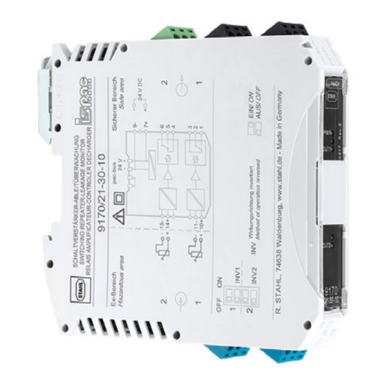
Anhang B Anhang B 15.1 Geräteaufbau Geräteelement Beschreibung Schwarze/grüne Anschlussklemmen für den sicheren Klemmen Bereich LED "PWR", grün Anzeige Hilfsenergie LED, rot ohne Funktion DIP-Schalter ohne Funktion Blaue Klemmen Anschlussklemmen für den Ex-Bereich (eigensicher Ex i) DIP-Schalter "INV1" Invertierung der Wirkungsrichtung für Kanal 1 9170 DIP-Schalter "INV2"... - Page 21 Operating instructions Additional languages r-stahl.com Switching repeater – Leakage monitor Type 9170/21-30-10...
- Page 22 Contents General Information ....................3 Manufacturer .......................3 About these Operating Instructions ..............3 Further Documents .....................3 Conformity with Standards and Regulations ............3 Explanation of the Symbols ................4 Symbols in these Operating Instructions ............4 Symbols on the Device ..................4 Safety ........................5 Intended Use .......................5 Personnel Qualification ..................5 Residual Risks ....................6 Transport and Storage ..................7...
-
Page 23: En En
• Data sheet For documents in additional languages, see r-stahl.com. Conformity with Standards and Regulations • Certificates and EU Declaration of Conformity: r-stahl.com. • The device has IECEx approval. See IECEx homepage: http://iecex.iec.ch/ to view the certificate. • Further national certificates can be downloaded via the following link: https://r-stahl.com/en/global/support/downloads/. -
Page 24: Explanation Of The Symbols
Explanation of the Symbols Explanation of the Symbols Symbols in these Operating Instructions Symbol Meaning Tip for making work easier DANGER! Dangerous situation which can result in fatal or severe injuries causing permanent damage if the safety measures are not complied with. -
Page 25: Safety
"Intended use" includes complying with these operating instructions and the other applicable documents, e.g. the data sheet. All other uses are only intended after being approved by R. STAHL. Personnel Qualification Qualified specialist personnel are required to perform the activities described in these operating instructions. -
Page 26: 3.3 Residual Risks
(see the "Technical data" chapter). Do not place any load on the device. Check the packaging and the device for damage. Report any damage to R. STAHL immediately. Do not commission a damaged device. Store the device in its original packaging in a dry place (with no condensation), and make sure that it is stable and protected against the effects of vibrations and knocks. -
Page 27: Transport And Storage
Transport and Storage Improper mounting, installation, commissioning, maintenance or cleaning Basic work such as installation, commissioning, maintenance or cleaning of the device must be performed only in accordance with the valid national regulations of the country of use and only by qualified persons. Otherwise the explosion protection can be rendered ineffective. This may result in explosions causing serious or even fatal injuries to persons in the vicinity. -
Page 28: Product Selection And Project Engineering
Product Selection and Project Engineering Product Selection and Project Engineering Install and set up the cabinet in such a way that all devices installed within it are always operated within their permissible temperature range (see cabinet installation guide). NOTICE! Malfunction or device damage in the event of improper circuitry. Non-compliance can result in material damage. - Page 29 Mounting and Installation 6.1.3 Mounting / Dismounting of the Device on DIN Rail and pac-Bus Mounting on DIN rail 06886E00 Position the device on the DIN rail. Position the cut-out of the enclosure on the outside edge of the DIN rail. ...
-
Page 30: 6.2 Installation
Mounting and Installation 6.1.4 Mounting / Dismounting pluggable Terminals All devices are equipped with pluggable terminals. Mounting Insert the terminal into the device until the terminal engages. Dismounting 10859E00 Position the screwdriver behind the terminal. Push out the terminal. Installation Operation under difficult conditions, in particular on ships, requires additional measures to be taken for correct installation, depending on the operating location. - Page 31 Mounting and Installation 6.2.2 Connection Pictures Use for temporary electrostatic grounding Zone 2 9170/21-30-10 Division 2 Zone 1 Division 1 20534E00 Legend = switching repeater – leakage monitor 9170 = supply connection (24 V DC) = output signal from the potential-free auxiliary contact for channel 1 = output signal from the potential-free auxiliary contact for channel 2 = Ex i input signal for channel 1 = Ex i input signal for channel 2...
- Page 32 Mounting and Installation Use for permanent electrostatic grounding Zone 2 9170/21-30-10 Division 2 Zone 1 Division 1 20535E00 Legend = switching repeater – leakage monitor 9170 = supply connection (24 V DC) = output signal from the potential-free auxiliary contact for channel 1 = output signal from the potential-free auxiliary contact for channel 2 = Ex i input signal for channel 1 = Ex i input signal for channel 2...
-
Page 33: Parameterization And Commissioning
Parameterization and Commissioning 6.2.4 Connection of Grounding Monitoring Terminal 9170/21-30-10 9191 9191 20533E00 • Ensure that only the labelled clamping units on the grounding monitoring terminal are contacted. 6.2.5 Circuitry with inductive Loads at the Output Schematic 15530E Connect inductive loads using a freewheeling diode. Do NOT connect using a varistor. -
Page 34: 8 Operation
Operation Operation Operation Operating principle The electrostatic charges generated, for instance, during loading and unloading of containers are eliminated and the circuit is monitored during operation. The monitoring is based on the evaluation of the contact resistance for equipotential bonding – starting from the switching repeater – leakage monitor 9170 via the object to be grounded, the connections on the equipotential bonding rail and back to the switching repeater –... -
Page 35: Maintenance, Overhaul, Repair
Only return or package the devices after consulting R. STAHL! Contact the responsible representative from R. STAHL. R. STAHL's customer service is available to handle returns if repair or service is required. Contact customer service personally. Go to the r-stahl.com website. -
Page 36: 11 Cleaning
NOTICE! Malfunction or damage to the device due to the use of non-original components. Non-compliance can result in material damage. Use only original accessories and spare parts from R. STAHL Schaltgeräte GmbH (see data sheet). Switching repeater – Leakage monitor... -
Page 37: Annex A
Annex A Annex A 14.1 Technical Data Marking Type designation 9170/21-30-10 CE marking 0158 Explosion Protection Global (IECEx) Gas and dust IECEx BVS 09.0041X Ex nA nC [ia Ga] IIC T4 Gc [Ex ia Da] IIIC Europe (ATEX) Gas and dust DMT 02 ATEX E 195 X E II 3 (1) G Ex nA nC [ia Ga] IIC T4 Gc E II (1) D [Ex ia Da] IIIC... - Page 38 Annex A Technical Data Electrical data Number of channels Auxiliary power Nominal voltage U 24 V DC Voltage range 18 to 31.2 V Residual ripple within ( 3.6 V voltage range Nominal current 50 mA Power consumption 1.2 W Max. power dissipation 1.2 W Polarity reversal protection Operation indication...
- Page 39 Mounting orientation vertical, horizontal Connection type Screw terminals, spring clamp terminals Conductor cross-section Solid: 0.2 to 2.5 mm Flexible: 0.2 to 2.5 mm For further technical data, see r-stahl.com. 202806 / 9170614310 Switching repeater – Leakage monitor 2020-08-31·BA00·III·en·03 Type 9170/21-30-10...
-
Page 40: Annex B
Annex B Annex B 15.1 Device Design Device component Description Black/green Connection terminals for the safe area terminals "PWR" LED, green Auxiliary power indication LED, red Non-functional DIP switch Non-functional Blue terminals Connection terminals for the hazardous area (intrinsically safe Ex i) DIP switch "INV1"... - Page 42 Type 9170/*1-**-1* Type 9170/*1-**-2* (for 24 V DC) (for 120 /230 V AC or with power relay) (only at (only at 9170/2) 9170/2) The Switching Repeater Type 9170/*1-*d-1* (d = 0, 1, 4) is an The Switching Repeater Type 9170/*1-**-2* and Type associated apparatus as well as a nonincendive apparatus for 9170/*1-*d-** (d = 2, 3) is an associated apparatus located in installation in non-hazardous or Class 1, Division 2 or Zone 2...
Need help?
Do you have a question about the ISpac 9170/21-30-10 and is the answer not in the manual?
Questions and answers