Table of Contents
Advertisement
Quick Links
Advertisement
Table of Contents

Related Manuals for Blastrac BDC-955


Summary of Contents for Blastrac BDC-955
- Page 1 OPERATING MANUAL BDC-955 VERSION 2.1...
-
Page 2: Ec Declaration Of Conformity
EC DECLARATION OF CONFORMITY in accordance with Appendix II sub A of Directive 2006/42/EC BLASTRAC B.V. Utrechthaven 12 NL - 3433 PN NIEUWEGEIN Tel: 0031 (0)30 601 88 66 Fax: 0031 (0)30 601 83 33 Info@Blastrac.nl The Netherlands We declare under our sole responsibility that the machine as described below conforms with the Health and Safety requirements of the European Directive for machine Safety. -
Page 3: Table Of Contents
Table of contents EC Declaration of Conformity 1. Introduction 2. Machine description Application & functioning 3. Safety Safety precautions - general Safety precautions - with regard to transport Safety regulations 4. Before operation Checkpoints of electrical safety 5. Operation Switch on the machine Work with the machine Emptying the dust bin Interrupting work... -
Page 4: Introduction
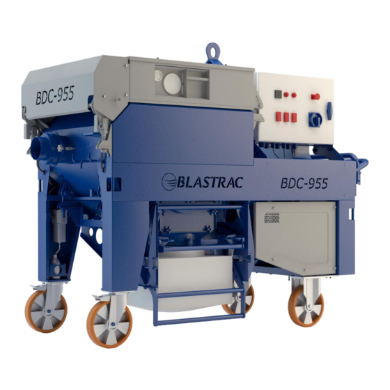
Class H13 HEPA filter in accordance with EN1822 The BDC-955 is available in 2 versions: 400-440 Volt 50 and 60Hz version. Application The BDC-955 is especially designed to be used in combination with Blastrac Blasting machines and scarifiers. Contact Blastrac B.V. for the correct execution and combinations. - Page 5 ITEM DESCRIPTION WHEELS FILTER CHAMBER PULSE CHAMBER CONTROL PANEL WATER SEPARATOR AIR PISTOL PULSE SYSTEM PULSE CONTROL FAN UNIT HOIST BEAM COMPRESSOR SILENCER END PART DISCHARGE & BAG UNIT COVERS HOSE ADAPTER BIG BAG FOR DETAIL OF CONTROL PANEL, SEE FIGURE 2.2 FIGURE 2.1 –...
- Page 6 FILTER CHAMBER Contains 9 filter cartridges for the separation of dust from the airflow. PULSE CHAMBER Separates the filter chamber from the ‘clean air’ side and seals the filtercartridges. CONTROL PANEL Controls the functioning of the dustcollector and powersupply to the applications (see figure 2.2). WATER SEPARATOR Separation of water from the pulse system.
- Page 7 DISCHARGE & BAG UNIT For dust discharge and handling of the dustbags. The discharge tray has an integrated valve which enables continuous working with the combined application. HOSE ADAPTER Accessory which enables connection of a 5” (130 mm.) suction hose, instead of the standard 6” (150 mm.) hose.
-
Page 8: Safety
Connectors Enables the connection of an application, e.g. a Blastrac blasting – or scarifying machine. Hour counter Shows the working time of the Dustcollector in hours. Registration of the working hours enables to follow a correct maintenance schedule. -
Page 9: Safety Regulations
Safety precautions – with regard to maintenance To allow the user to carry out maintenance operations, the dust collector must be disassembled, cleaned and inspected as far as reasonably possible, without causing hazards for the maintenance staff or other people. The suitable precautions include decontamination before disassembling the dust collector, adequate ... -
Page 10: Before Operation
4. Before operation Before using the machine it is essential to inspect the machine. It is not permitted to use the machine if the machine safety is not according the checkpoints below. Checkpoints of electrical safety Use only extension cables for extending the main cable that are sized and marked in accordance with ... -
Page 11: Exchanging The Dustbag
Exchanging the dustbag The dust-bag can be replaced during working with the dust-collector by closing the valve on the discharge- outlet. The capacity of the discharge-bin enables continuation of the working process. Check regularly the level of the dust-bag. The periods of checking depends on the surface to be cleaned. -
Page 12: Maintenance
6. Maintenance Pay attention to Chapter 3 "Safety" during maintenance and repair works. Failures due to inadequate or incorrect maintenance may generate very high repair costs and long standstill periods of the dust collector. Regular maintenance therefore is imperative. Operational safety and service life of the dust collector depend, among other things, on proper maintenance. The following table shows recommendations about time, inspection and maintenance for the normal use of the dust collector. -
Page 13: Filter Replacement
Store the cleaned and dry machine in a dry and humid free room. Protect the electrical motors from moisture, heat, dust and shocks. All repair work must to be done by qualified Blastrac personnel, this to guarantee a safe and reliable machine. Any guarantee on the machine is expired when: Non original Blastrac parts have been used ... -
Page 14: Pulse System
FIGURE 6.2 11 Follow above given procedures in reverse to restore the pulse-chamber position. Carefully and evenly tension (in cross-direction) the bolts and nuts in order to obtain an adequate sealing. Torque the tension devices with 26 up to 30 Nm. 12 When hose and hoisting beam are mounted back in position, start the fan-unit. - Page 15 The conditioned air then passes a control valve (see fig. 6.5), which regulates the systems pressure , and then builds up pressure in the pulse tank. Control valve FIGURE 6.5 Pulse tank Safety valve Normally the pressure in the system lies between 6 and 7 bar. The safety valve mounted on the pulse tank is activated at approximately 10 bar.
- Page 16 When there is pressure but the pulse system does not function, there might be a problem in the electrical system which controls the pulsing system. Check the wiring and the PLC-settings. FIGURE 6.7 Advised is to take contact with Blastrac Support in order to prevent operational problems. Water separator Periodically check the level indicator of the waterseparator.
- Page 17 In case of less air flow as mentioned in the paragraph above, replace the filter of the waterseparator as following: Push unlocking slide down and turn filter bowl in anti-clockwise direction. Then pull filter bowl away from the separator. FIGURE 6.10 Turn the filter screw loose and replace the dirty filter by a new one as shown on figure 6.11 .
- Page 18 FIGURE 6.12 FIGURE 6.13 Compressor The oil level and air filter of the compressor should periodically be inspected acc. to the inspection table given values. Replacement or cleaning of the air filter is depending on the environment in which the Dust collector is operating.
- Page 19 The height of the oil level oil level must lay on approximately half of the oil level indicator , about 0,25 liter. FIGURE 6.15 Use only oil especially mend for compressors, according specification C.T. 68 ( ISO 68 – viscosity ) . Prior to draining-off , the compressor unit should have operating temperature.
-
Page 20: Technical Data
820 mm Height 1500 mm Weight, with cable ( / cable loose) 552 kg ( / 538 kg) Noise level (at 1 mtr. distance) Up to 95 dB(A) Design and specifications are subject to change without notice by Blastrac B.V. -
Page 21: Contact
Headquarter Blastrac Poland Blastrac Italy Blastrac The Netherlands Golina, Dworcowa 47a S.S. 10 Padana Inferiore, 41 Utrechthaven 12 PL – 63-200 Jarocin IT – 29012 Caorso (PC) NL – 3433 PN Nieuwegein Tel – 0048 627 40 41 50 Tel – 0039 0523 81 42 41 Tel –...
Need help?
Do you have a question about the BDC-955 and is the answer not in the manual?
Questions and answers