Table of Contents
Advertisement
Advertisement
Table of Contents

Subscribe to Our Youtube Channel
Related Manuals for Blastrac BMR-75D


Summary of Contents for Blastrac BMR-75D
- Page 1 OPERATING MANUAL BMR-75D VERSION 1.0 www.blastrac.com 1-800-256-3440...
-
Page 2: Table Of Contents
Table of Contents 1. Introduction ............................3 2. Machine Description ..........................3 3. Safety ..............................4 Safety Precautions ..........................4 Safety Regulations ..........................4 Safety Instructions ..........................5-7 Engine Safety ........................... 5-7 4. Initial Operation............................. 8 Checkpoints of Machine Safety: ......................8 5. -
Page 3: Introduction
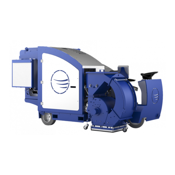
Only authorized and trained personnel may operate this machine. 2. Machine Description The Blastrac BMR-75D ride-on shot blaster is ideally suited for medium and large sized applications with the added benefit of being diesel operated for increased versatility. It is very maneuverable with zero turn radius, non-mark tires and complete hydraulic control. -
Page 4: Safety
Blasthead Access Door Steering Wheel Hepa Shifter Dust Collector Control panel 3. Safety It is important that all persons who are working with or maintaining this machine must read the manual carefully and understand it fully. Always keep this manual with the machine, so it can be referenced to at any time. Safety Precautions Make sure that persons who are not operating the machine are not in the surrounding area of the ▪... -
Page 5: Safety Instructions
Turn key to OFF when machine is parked. ▪ Park the machine always on a flat horizontal and levelled surface. The weight of the BMR-75D is 5200 pounds. Only use an appropriately sized lift to move/hoist the BMR- ▪ 75D. The forklift pockets are shown below (1). - Page 6 Do not run the machine in unsafe environments. ▪ Only operate this machine when sitting in the operator seat. ▪ DO NOT OPERATE THIS MACHINE WHEN STANDING IN FRONT OF IT!
-
Page 7: Engine Safety
Engine Safety DANGER: Engine exhaust gases contain poisonous carbon monoxide. Carbon monoxide is odorless and colorless and can cause injury or death if inhaled. Do not use equipment indoors without adequate ventilation. Refer to OSHA guidelines and regulations concerning maximum levels of exposure to carbon monoxide gases and other hazards associated with using internal combustion engines. -
Page 8: Initial Operation
4. Initial Operation Before using the machine it is essential to inspect the machine every day. It is not permitted to use the machine if it does not pass all of the checkpoints below. Checkpoints of Machine Safety: Shifter should be in the neutral position. ▪... -
Page 9: Operation
5. Operation During the operation of the BMR-75D, the following additional safety instructions must be followed closely. Switching on the Machine: Take place on the seat. Operating the machine without being seated is not possible because of the safety ▪... -
Page 10: Driving The Machine
Driving the Machine The drive wheels are controlled by the shifter. Pushing the shifter (1) forward makes the machine go forward and pushing it back makes the machine go in reverse. The driving speed depends on the position of the shifter. The steering wheel (2) controls the front wheel, controlling the direction the machine goes. -
Page 11: Controlling The Blasthead
Controlling the Blasthead Pressing the free float button (1) will lower the Blasthead down to the ground. To raise the BlastHead hold the up button (2) until it is at the desired height. The Clutch On Button (3) will engage the clutch and run up the blast wheel and blower. - Page 12 Order of operation Start up - Start the BMR-75 - Run the machine up to 2200 RPM - Press the free float button and wait for it to lower - Turn the clutch on - Run the machine to the desired speed - Open the shot valve Shut down - Close the shot valve...
- Page 13 Failures due to inadequate or incorrect maintenance may generate very high repair costs and long downtimes of the BMR-75D. Regular maintenance, therefore, is imperative. Operational safety and service life of the shot blaster depend, among other things, on proper maintenance.
- Page 14 Store the cleaned and dry machine in a dry and humid free room. Protect the components from moisture, heat, dust and shocks. All repair work must to be done by qualified Blastrac personnel, this is to guarantee a safe and reliable machine. Any guarantee on the machine is expired when: Non original Blastrac parts have been used ▪...
-
Page 15: Hydraulic System Instruction
To check the oil level there is an indicator (1) installed on the side of the tank. The indicator can be seen from the driver side of the BMR-75D under the diesel tank door. The level shouldn’t be lower than half the range of the indicator. - Page 16 At least one time during the year or every 150 hours the oil from system and filter should be replaced. For this operation disconnect the battery. The oil drain plug is located on the back of the machine near the rear axle. You can refill the hydraulic oil from the diesel tank access door.
-
Page 17: Blasthead And Scarifier
7. Blasthead and Scarifier Blasthead To take the blast wheel out you will need to do the following steps Remove the bearing cover Remove the side cover with the bearing on it Remove the outer liner Remove the lower and upper inner liners Pull the blast wheel out... - Page 18 Scarifier To take the Scarifier drum out you will need to do the following steps Unbolt the three bolts holding the door closed Pull the door straight out then hinge it to the side Take the two nuts and the plate that hold the drum in Pull the drum out...
-
Page 19: Attachement Swap
Attachment Swap Removing the Blasthead Disconnect the dust collector hose from the Blasthead by taking off the hose clamp holding it on to the Blasthead. Remove the cover and belt guard from the frame by taking out the twelve M6 hex cap screws. - Page 20 Use the tensioner wrench to loosen the belt tensioner and take the belt (1800-8M-50) off of the Blasthead pully and the jack shaft. Then unplug the linear actuator from the machine.
- Page 21 Use the dent puller to remover the shaft out of the Blasthead and the Blasthead mount. Unclip the pin that holds the hydraulic cylinder to the Blasthead and remove the pin.
- Page 22 Roll the Blasthead away from the BMR-75.
- Page 23 Open the side door and loosen the tensioner between the clutch and the jack shaft with a 17mm wrench and take off the belt (1520-8m-50).
- Page 24 Unbolt the jack shaft with the two 48-8M-50 pulleys using a 22mm ratchet then remove it from the frame. Then take out the two set screws using a 8mm allen wrench and take the taper lock off the clutch pulley (112-8M-50) and then remove the pulley.
- Page 25 Attaching the Scarifier Repostion the tensioner for the blast head to the front hole for the scarifier head.
- Page 26 Put the new pulley 56-8M-50 and taperlock on the clutch shaft using a 6mm allen wrench. Bolt the new jack shaft assembly into place with the 56-8M-50 pulley on the outside and the 30-8M-50 pulley on the inside using a 22mm ratchet.
- Page 27 Put the 1304-8M-50 belt on between the clutch and jackshaft, then tighten the tensioner up using a 17mm ratchet.
- Page 28 Roll the Scarifier head up to the BMR-75.
- Page 29 Put the bar in to hold the Scarifier head to the frame and then line up the hydraulic cylinder with the lifting point and put the pin in.
- Page 30 Put belt 2304-8M-50 on the scarifier head and the jack shaft. Then use the tensioner wrench to tension the belt.
- Page 31 Bolt the cover onto to the frame of the BMR-75 using tweleve M6 hex cap screws. Then bolt the belt guard on to the side of the scarifier head with M6 bolts.
-
Page 32: Technical Data
Technical Data BMR-75D Working width 16” / 13.2” Shotblasting / Scarifiying Motor power 75 HP Drive system/ Speed Diesel- up to 330ft/min Machine type Ride-on Application Asphalt / Concrete / Steel Length 120” Width 62” Height 65” Weight 5200 lbs. - Page 33 11. Contact Blastrac NA 13201 North Santa Fe Avenue Oklahoma City, OK 73114 Tel: 800-256-3440 Fax: 405-478-8608 www.blastrac.com...
Need help?
Do you have a question about the BMR-75D and is the answer not in the manual?
Questions and answers
on average how much surface area can this cover per hour
The Blastrac BMR-75D has a production capacity of 4,500 square feet per hour on average.
This answer is automatically generated