
Related Manuals for Nexcom XPPC-24-100


Summary of Contents for Nexcom XPPC-24-100
- Page 1 NEXCOM International Co., Ltd. Intelligent Platform & Services Business Unit Wide Screen Touch Computer XPPC 24-100 User Manual NEXCOM International Co., Ltd. www.nexcom.com Published July 2020...
-
Page 2: Table Of Contents
Rear Bottom ..................4 USB Touch ..................18 Rear Top ....................4 System Power Button Header ............18 Rear ....................5 DC Power Input ................19 Mechanical Dimensions ................6 FAN Connector ................19 Copyright © 2020 NEXCOM International Co., Ltd. All Rights Reserved. XPPC 24-100 User Manual... - Page 3 Default Configuration ................31 Entering Setup ..................31 Legends ....................31 BIOS Setup Utility ..................33 Main ....................33 Advanced ..................34 Chipset ....................41 Security .....................44 Boot ....................45 Save & Exit ..................46 Copyright © 2020 NEXCOM International Co., Ltd. All Rights Reserved. XPPC 24-100 User Manual...
-
Page 4: Preface
No describes how to keep the system CE compliant. part of this manual may be reproduced, copied, translated or transmitted in any form or by any means without the prior written consent from NEXCOM Declaration of Conformity International Co., Ltd. -
Page 5: Rohs Compliance
(Cr6+) < 0.1% or 1,000ppm, Polybrominated biphenyls (PBB) < 0.1% or 1,000ppm, and Polybrominated diphenyl Ethers (PBDE) < 0.1% or 1,000ppm. In order to meet the RoHS compliant directives, NEXCOM has established an engineering and manufacturing task force to implement the introduction of green products. -
Page 6: Warranty And Rma
2. For NEXCOM Panel PC product lines (the APPC, MPPC series), they are NEXCOM in advance. also guaranteed against defect in materials and workmanship for the period of twenty-four (24) months in their motherboard design. - Page 7 RMA that NEXCOM has determined not to be covered by the warranty will customer registered delivery address will incur an extra shipping charge, be charged the NEXCOM Standard Repair Fee for the repairing. If a RMA is the customer is responsible for paying the extra shipping charges, duties, determined to be not repairable, customer will be notified and product(s) and taxes of this shipment.
- Page 8 Basic Labor Cost and Testing Fee: as Table listed. b. Parts Fee: NEXCOM will charge for main IC chipsets such as the N.B., S.B., Super-IO, LAN, Sound, Memory, and so on. c. 3rd-party Device Fee: products replacement for CPU, DIMM, HDD, Chassis, and UPS.
-
Page 9: Safety Information
There is a danger of explosion if battery is incorrectly replaced. Replace only with the same or equivalent type recommended by the manufacturer. Discard used batteries according to the manufacturer’s instructions. Copyright © 2020 NEXCOM International Co., Ltd. All Rights Reserved. XPPC 24-100 User Manual... -
Page 10: Safety Precautions
CAUTION: Risk of explosion if battery is replaced by an incorrect type. Dispose of used batteries according to the instructions. 10. All cautions and warnings on the equipment should be noted. Copyright © 2020 NEXCOM International Co., Ltd. All Rights Reserved. XPPC 24-100 User Manual... -
Page 11: Technical Support And Assistance
Preface Technical Support and Assistance Conventions Used in this Manual 1. For the most updated information of NEXCOM products, visit NEXCOM’s Warning: website at www.nexcom.com. Information about certain situations, which if not observed, can cause personal injury. This will prevent injury to yourself 2. -
Page 12: Global Service Contact Information
16F, No.250, Sec. 2, Chongde Rd., Beijing, 100094, China Beitun Dist., Tel: +86-10-5704-2680 Taichung City 406, R.O.C. Fax: +86-10-5704-2681 Tel: +886-4-2249-1179 Email: sales@nexcom.cn Fax: +886-4-2249-1172 www.nexcom.cn Email: sales@nexcom.com.tw www.nexcom.com.tw Copyright © 2020 NEXCOM International Co., Ltd. All Rights Reserved. XPPC 24-100 User Manual... - Page 13 Tokyo, 108-0014, Japan No. 609, Yunlin East Rd., Tel: +81-3-5419-7830 Shanghai, 200062, China Fax: +81-3-5419-7832 Tel: +86-21-5278-5868 Email: sales@nexcom-jp.com Fax: +86-21-3251-6358 www.nexcom-jp.com Email: renwang@nexcom.com.tw www.nexcom.cn xiii Copyright © 2020 NEXCOM International Co., Ltd. All Rights Reserved. XPPC 24-100 User Manual...
-
Page 14: Package Contents
NI+Heat Treatment 6012200053X00 Zipper Bag PE Zipper Bag #3 100x70mm, w/China RoHS Symbol Antistatic Air Bag for Chimera 15P6 VER:A FULPAK (330+330) 6012200188X00 Bubble Wrap x450mm Color:Red Copyright © 2020 NEXCOM International Co., Ltd. All Rights Reserved. XPPC 24-100 User Manual... -
Page 15: Ordering Information
Celeron J3455 ® ® Panel Mount Kit (P/N: 88W30XPPC00X0) Panel mount kit for XPPC 24-100 Open Frame Kit (P/N: 88W30XPPC01X0) Open frame kit for XPPC 24-100 Copyright © 2020 NEXCOM International Co., Ltd. All Rights Reserved. XPPC 24-100 User Manual... -
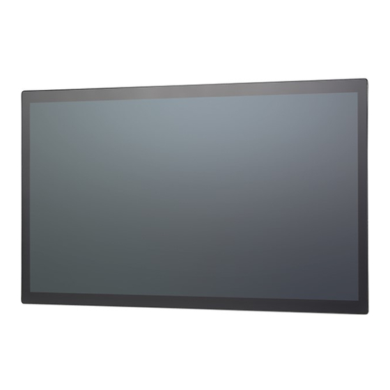
Page 16: Xppc 24-100
J3455, Quad Core, 1.50 GHz ® ® ▪ 1 x DDR3L up to 8GB, M.2 M-key 2242 for storage device ▪ Support power input 19 VDC Copyright © 2020 NEXCOM International Co., Ltd. All Rights Reserved. XPPC 24-100 User Manual... -
Page 17: Hardware Specifications
– IEC 68 2-27 ▪ 1 x mini-PCIe full-size connector with SIM slot (full-size) on board, – 20g peak acceleration (11 msec. duration) supports Wi-Fi/LTE module Copyright © 2020 NEXCOM International Co., Ltd. All Rights Reserved. XPPC 24-100 User Manual... - Page 18 Certification ▪ CE (EN55035 + EN55032) ▪ FCC Class A (EMI part 15B) ▪ LVD (EN62368-1) Operating System Support ▪ Windows 10 64-bit ▪ Linux 4.1 Copyright © 2020 NEXCOM International Co., Ltd. All Rights Reserved. XPPC 24-100 User Manual...
-
Page 19: Knowing Your Xppc 24-100
Used to connect a headphone or a speaker. Power Line-out Switch HDMI Power LED USB 3.0 HDMI Used to connect an HDMI interface monitor. DC Input LAN1 & LAN2 Copyright © 2020 NEXCOM International Co., Ltd. All Rights Reserved. XPPC 24-100 User Manual... -
Page 20: Rear
Chapter 1: Product Introduction Rear VESA Mounting Hole VESA Mounting Hole VESA Mounting Hole VESA Mounting Hole VESA Mounting Holes These are the mounting holes for VESA mount (100x100mm) Copyright © 2020 NEXCOM International Co., Ltd. All Rights Reserved. XPPC 24-100 User Manual... -
Page 21: Mechanical Dimensions
Chapter 1: Product Introduction Mechanical Dimensions 237.85 557.00 546.70 55.00 MINIMUM CUT OUT SIZE 237.85 21.50 100.00 528.04 14.48 14.48 CUT OUT THICKNESS T=9.50mm (MAX) Copyright © 2020 NEXCOM International Co., Ltd. All Rights Reserved. XPPC 24-100 User Manual... -
Page 22: Chapter 2: Jumpers And Connectors
Static electricity can damage many of the electronic ▪ Use correct screws and do not over tighten screws. components. Humid environments tend to have less static electricity than Copyright © 2020 NEXCOM International Co., Ltd. All Rights Reserved. XPPC 24-100 User Manual... -
Page 23: Jumper Settings
(on) and open (off). Two-Pin Jumpers: Open (Left) and Short (Right) Three-Pin Jumpers: Pins 1 and 2 are Short Copyright © 2020 NEXCOM International Co., Ltd. All Rights Reserved. XPPC 24-100 User Manual... -
Page 24: Locations Of The Jumpers And Connectors For Xppc 24-100
XPPC 24-100. It shows the locations of the jumpers and connectors. CLRCT W_USB BTL_PWM BATTERY1 PWR_SW Top View LED_CON ATX_AT MINI_CARD FAN1 LVDS_PWR LVDS NXM_DEBUG LINE_OUT CON1 RESET COM2 COM1 DC_PWR LAN2 LAN1 HDMI1 COM1 USB1 Copyright © 2020 NEXCOM International Co., Ltd. All Rights Reserved. XPPC 24-100 User Manual... -
Page 25: Bottom View
Chapter 2: Jumpers and Connectors Bottom View Copyright © 2020 NEXCOM International Co., Ltd. All Rights Reserved. XPPC 24-100 User Manual... -
Page 26: Jumpers & Dip Switches
Connector location: CLRTC Settings Settings 1-2 On ATX Mode 1-2 On Normal 2-3 On AT Mode 2-3 On Clear CMOS 1-2 On: default 1-2 On: default Copyright © 2020 NEXCOM International Co., Ltd. All Rights Reserved. XPPC 24-100 User Manual... -
Page 27: Lvds Panel Voltage Select
Connector type: 1x3 3-pin header, 2.0mm pitch Connector location: LVDS_PWR Connector location: BLT_PWM Settings Settings 1-2 On 3.3V 1-2 On 3.3V 2-3 On 2-3 On 1-2 On: default 2-3 On: default Copyright © 2020 NEXCOM International Co., Ltd. All Rights Reserved. XPPC 24-100 User Manual... -
Page 28: Lvds Resolution Select
1680 x 1050 8-bit Dual Port 1101 1600 x 1200 8-bit Dual Port 1110 1920 x 1080 8-bit Dual Port 1111 1920 x 1200 8-bit Dual Port Copyright © 2020 NEXCOM International Co., Ltd. All Rights Reserved. XPPC 24-100 User Manual... -
Page 29: Connector Pin Definitions
Chapter 2: Jumpers and Connectors Connector Pin Definitions External Connector COM1 DB9 Male Connector Connector type: DB-9 port, 9-pin D-Sub Connector location: COM1 Definition Definition Copyright © 2020 NEXCOM International Co., Ltd. All Rights Reserved. XPPC 24-100 User Manual... -
Page 30: Internal Connectors
Connector type: 1x7 7-pin header JST, 2.5mm pitch Connector type: 1x2 2-pin header, 2.54mm pitch Connector location: INV Connector location: RESET Definition Definition Definition RESET# Backlight Control Backlight Enable Copyright © 2020 NEXCOM International Co., Ltd. All Rights Reserved. XPPC 24-100 User Manual... -
Page 31: Led Connector
Connector type: 1x5 5-pin header JST, 2.0mm pitch Connector type: 1x2 2-pin header, 2.54mm pitch Connector location: LED_CON Connector location: JP1 Definition Definition Definition HDD_LED- HDD_LED+ HDD_LED+ Standby LED HDD_LED- PWR LED Copyright © 2020 NEXCOM International Co., Ltd. All Rights Reserved. XPPC 24-100 User Manual... -
Page 32: Line-Out Connector
Connector type: 1x4 4-pin header, 2.0mm pitch Connector type: 2x5 10-pin header Connector location: LINE_OUT Connector location: J2 Definition Definition Definition Definition LOUT_L +5V_USB2_P45 LOUT_JD LOUT_R S_USB2DN4 S_USB2DP4 S_USB2DP5 S_USB2DN5 +5V_USB2_P45 Copyright © 2020 NEXCOM International Co., Ltd. All Rights Reserved. XPPC 24-100 User Manual... -
Page 33: Usb Touch
Connector type: 1x6 6-pin header JST, 2.5mm pitch Connector type: 1x2 2-pin header JST, 2.0mm pitch Connector location: W_USB Connector location: J1 Definition Definition Definition +5V_USB2_P2 S_USB2DN2 S_USB2DP2 S_USB2DN6 PWRBTN# S_USB2DP6 Copyright © 2020 NEXCOM International Co., Ltd. All Rights Reserved. XPPC 24-100 User Manual... -
Page 34: Dc Power Input
Connector type: 1x2 2-pin header, 3.96mm pitch Connector type: 1x4 4-pin header, 2.54mm pitch Connector location: CON1 Connector location: FAN1 Definition Definition Definition +12V +DC_IN FAN SPEED DETECT FAN SPEED CONTROL Copyright © 2020 NEXCOM International Co., Ltd. All Rights Reserved. XPPC 24-100 User Manual... -
Page 35: Debug Port/Lpc Bus Connector
Connector type: 1x10 10-pin header, 1.0mm pitch Connector type: 1x9 9-pin header, 1.0mm pitch Connector location: NXM_DEBUG Connector location: COM2 Definition Definition Definition Definition SERIRQ LAD0 LAD1 LAD2 LAD3 LFRAME# 25MHZ PLTRST# Copyright © 2020 NEXCOM International Co., Ltd. All Rights Reserved. XPPC 24-100 User Manual... -
Page 36: Battery Connector
+V_PANEL (3.3V or 5V) +V_PANEL (3.3V or 5V) +V_PANEL (3.3V or 5V) 3.3V LVDS0_CLK+ LVDS0_CLK- SMBUS_CLK Backlight Enable Backlight Control LVDS1_CLK+ LVDS1_CLK- +12V +12V +12V SMBUS_DAT Copyright © 2020 NEXCOM International Co., Ltd. All Rights Reserved. XPPC 24-100 User Manual... -
Page 37: Mini-Pcie Connector
WAKE# +3VSB +1.5V SMB_CLK +1.5V PETn0 SMB_DATA SIM_PWR PETp0 SIM_DATA USB_D- REFCLK- SIM_CLK USB_D+ REFCLK+ SIM_RESET +3VSB SIM_VPP +3VSB WLAN_DISABLE# RESET# +1.5V PERn0 +3VSB PERp0 +3VSB Copyright © 2020 NEXCOM International Co., Ltd. All Rights Reserved. XPPC 24-100 User Manual... -
Page 38: Connector (M-Key)
M.2 Connector (M-Key) Connector location: M2M Definition Definition Definition Definition +3VSB +3VSB SATA_RXP SATA_RXN M2M_LED# SATA_TXN +3VSB SATA_TXP RESET# +3VSB +3VSB +3VSB +3VSB +3VSB +3VSB DEVSLP Copyright © 2020 NEXCOM International Co., Ltd. All Rights Reserved. XPPC 24-100 User Manual... -
Page 39: Chapter 3: System Setup
Prior to removing the top cover, make sure the unit’s power CAUTION! CAUTION! CAUTION! is off and disconnected from the power sources to prevent electric shock or system damage. Copyright © 2020 NEXCOM International Co., Ltd. All Rights Reserved. XPPC 24-100 User Manual... -
Page 40: Installing A Wi-Fi Or Lte Module (Mini-Pcie)
2 screws on the IO bracket, then remove the mainboard from module into the slot. Then secure the module with a screw. the chassis. Copyright © 2020 NEXCOM International Co., Ltd. All Rights Reserved. XPPC 24-100 User Manual... -
Page 41: Installing Vesa Mount Kit
Recommended screws for the VESA mount kit: 4 * M4x8 screws. 8 * Screws (F3x5 Nylok NI+Heat) Copyright © 2020 NEXCOM International Co., Ltd. All Rights Reserved. XPPC 24-100 User Manual... -
Page 42: System Dimensions With Open Frame Kit
Chapter 3: System Setup System Dimensions with Open Frame Kit 579.30 MINIMUM CUT OUT SIZE 557.00 237.85 100.00 4.50 4.50 14.48 528.04 14.48 4.50 4.50 579.30 Copyright © 2020 NEXCOM International Co., Ltd. All Rights Reserved. XPPC 24-100 User Manual... -
Page 43: Panel Mounting
CUT OUT SIZE T=9.50mm (MAX) 3. Slide the panel PC through the hole until it is properly fitted against the panel. 12 * Screws (F3x5 Nylok NI+Heat) Copyright © 2020 NEXCOM International Co., Ltd. All Rights Reserved. XPPC 24-100 User Manual... - Page 44 5. Tighten the clamp’s screw until it touches the panel. Panel Clamp Do not overtighten the screws to prevent damaging the CAUTION! CAUTION! CAUTION! Panel PC. Copyright © 2020 NEXCOM International Co., Ltd. All Rights Reserved. XPPC 24-100 User Manual...
-
Page 45: Chapter 4: Bios Setup
BIOS is updated in the future. second, to make settings appropriate for the way you use the computer. To check for the latest updates and revisions, visit the NEXCOM website at When to Configure the BIOS www.nexcom.com.tw. -
Page 46: Default Configuration
Powering on the computer and immediately pressing <Del> allows you to enter Setup. Load optimized default values. Press the key to enter Setup: Saves and exits the Setup program. Press <Enter> to enter the highlighted sub-menu Copyright © 2020 NEXCOM International Co., Ltd. All Rights Reserved. XPPC 24-100 User Manual... - Page 47 When “” appears on the left of a particular field, it indicates that a submenu which contains additional options are available for that field. To display the submenu, move the highlight to that field and press Copyright © 2020 NEXCOM International Co., Ltd. All Rights Reserved. XPPC 24-100 User Manual...
-
Page 48: Bios Setup Utility
F2: Previous Values System Date [Mon 01/13/2020] F3: Optimized Defaults System Time [16:42:16] F4: Save & Exit ESC: Exit Version 2.18.1263. Copyright (C) 2020 American Megatrends, Inc. Copyright © 2020 NEXCOM International Co., Ltd. All Rights Reserved. XPPC 24-100 User Manual... -
Page 49: Advanced
The options are Suspend Disabled and S3 (Suspend to RAM). Version 2.18.1263. Copyright (C) 2020 American Megatrends, Inc. Restore AC Power Loss Configures the power state when power is re-applied after a power failure. Copyright © 2020 NEXCOM International Co., Ltd. All Rights Reserved. XPPC 24-100 User Manual... - Page 50 Displays the IO address and IRQ of the serial COM port. Onboard Serial Port Mode Select this to change the serial port mode to RS232, RS422, RS485 No Terminator or RS485 With Terminator. Copyright © 2020 NEXCOM International Co., Ltd. All Rights Reserved. XPPC 24-100 User Manual...
- Page 51 Detects and displays the current system temperature. CPU Fan Speed Detects and displays the current CPU fan speed. VCORE to 1.35VDUAL Detects and displays the output voltages. Copyright © 2020 NEXCOM International Co., Ltd. All Rights Reserved. XPPC 24-100 User Manual...
- Page 52 When this field is set to Enabled, the VMM can utilize the additional hardware capabilities provided by Vanderpool Technology. VT-d Enables or disables VT-d function on MCH. Copyright © 2020 NEXCOM International Co., Ltd. All Rights Reserved. XPPC 24-100 User Manual...
- Page 53 F4: Save & Exit ESC: Exit Version 2.18.1263. Copyright (C) 2020 American Megatrends, Inc. Version 2.18.1263. Copyright (C) 2020 American Megatrends, Inc. EIST Enables or disables Intel ® SpeedStep. Copyright © 2020 NEXCOM International Co., Ltd. All Rights Reserved. XPPC 24-100 User Manual...
- Page 54 Enables or disables UEFI network stack. Enables or disables BIOS support for security device. O.S will not show Security Device. TCG EFI protocol and INT1A interface will not be available. Copyright © 2020 NEXCOM International Co., Ltd. All Rights Reserved. XPPC 24-100 User Manual...
- Page 55 XHCI ownership change should be claimed by the XHCI driver. USB Mass Storage Driver Support Enables or disables USB mass storage driver support. USB transfer time-out The time-out value for control, bulk, and Interrupt transfers. Copyright © 2020 NEXCOM International Co., Ltd. All Rights Reserved. XPPC 24-100 User Manual...
-
Page 56: Chipset
Version 2.18.1263. Copyright (C) 2020 American Megatrends, Inc. SMBus Support Version 2.18.1263. Copyright (C) 2020 American Megatrends, Inc. Enables or disables SMBus support. Setting incorrect field values may cause the system to malfunction. Copyright © 2020 NEXCOM International Co., Ltd. All Rights Reserved. XPPC 24-100 User Manual... - Page 57 ESC: Exit Version 2.18.1263. Copyright (C) 2020 American Megatrends, Inc. Version 2.18.1263. Copyright (C) 2020 American Megatrends, Inc. HD-Audio Support Enables or disables HD Audio support. Copyright © 2020 NEXCOM International Co., Ltd. All Rights Reserved. XPPC 24-100 User Manual...
- Page 58 OS. Please do not disable it unless for debugging purposes. SATA Test Mode Enables or disables SATA test mode. Port 0 Enables or disables SATA port 0. Port 1 Enables or disables SATA port 1. Copyright © 2020 NEXCOM International Co., Ltd. All Rights Reserved. XPPC 24-100 User Manual...
-
Page 59: Security
Select this to reconfigure the administrator’s password. USB Power State in S5 User Password Configures the USB power state in S5. Select this to reconfigure the user’s password. Copyright © 2020 NEXCOM International Co., Ltd. All Rights Reserved. XPPC 24-100 User Manual... -
Page 60: Boot
When set to Off, the function of the numeric keypad is the arrow keys Quiet Boot Enabled Displays OEM logo instead of the POST messages. Disabled Displays normal POST messages. Copyright © 2020 NEXCOM International Co., Ltd. All Rights Reserved. XPPC 24-100 User Manual... -
Page 61: Save & Exit
Restore Defaults To restore the BIOS to default settings, select this field then press <Enter>. A dialog box will appear. Confirm by selecting Yes. Copyright © 2020 NEXCOM International Co., Ltd. All Rights Reserved. XPPC 24-100 User Manual...
Need help?
Do you have a question about the XPPC-24-100 and is the answer not in the manual?
Questions and answers