
Related Manuals for SystemAir F-B90


Summary of Contents for SystemAir F-B90
- Page 1 F-B90 Multi-blade Fire damper User Manual Document in original language | · A001...
- Page 2 This also applies to products already ordered, as long as it does not affect the previously agreed specifications. Systemair is not liable or bound by the warranty if these instructions are not adhered to during installation or service. | A001...
-
Page 3: Table Of Contents
Contents Introduction ...........2 Warnings............3 Operating Conditions........3 Installation.............4 Installation Methods .......4 Opening Preparation for F-B90 Installation..........6 4.2.1 Opening Preparation for a Rigid Wall .........6 4.2.2 Opening Preparation for a Flexible Wall......7 Installation Distances ......8 Handling and manipulation of F- B90.............9 Wet Installation........13 4.5.1... - Page 5 Good to know Current information on all products is available at https://design.systemair.com | A001...
-
Page 6: Introduction
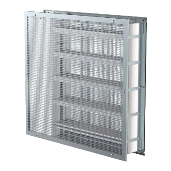
| Introduction Introduction This is the original installation, inspection and operating instructions document for the F-B90 fire damper. EVERY F-B90 FIRE DAMPER NEEDS TO BE INSTALLED IN ACCORDANCE WITH THIS DOCUMENT! F-B90 Multiblade Fire damper or Air Transfer Grille with performance rating EI90S or EI120S. -
Page 7: Warnings
Warnings | Warnings To avoid injury, make sure to wear gloves and keep the blades movement area clear while manipulating with the damper. Important Do not install non-functioning dampers! Operating Conditions Fire dampers can be defined as fire shutters for ventilation ducts in the place where they pass through walls or ceilings, which are the borders of the fire area. -
Page 8: Installation
• The distance between fire damper and the adjacent wall/ceiling and the fire damper must be at least 75 mm. • When the F-B90 fire damper is installed into a smoke and fire partition structure, it must be placed so that the damp- er blades in its closed position are located inside this structure. - Page 9 Installation | Table 2 Permitted installation methods for usage as air transfer grille Construction Type per EN 1363-1/ Minimal Thickness (mm) Dimension Designated Range Classification Usage (mm) Soft Crossing Air transfer Rigid/125 Flexible/ grille, EI120(v i ↔ o) S Wall Flexible/125 without 200 ×...
-
Page 10: Opening Preparation For F-B90 Installation
| Installation Opening Preparation for F-B90 Installation The F-B90 fire damper can be installed in a supporting construction. 4.2.1 Opening Preparation for a Rigid Wall Fig. 1 Rigid wall/ceiling with a rectangular opening Note: Dimensions W and H are defined in every installation... -
Page 11: Opening Preparation For A Flexible Wall
Installation | 4.2.2 Opening Preparation for a Flexible Wall Fig. 2 Flexible (plasterboard) wall with a rectangular opening and vertical cross-section Note: Dimensions W and H are defined in every installation Table 6 Legend On each side - 2 layers of plasterboard fireproof plate type F, EN 520 Vertical CW-profiles (profiles with s based on fire resistivity) Horizontal UW-profiles (profile with s... -
Page 12: Installation Distances
| Installation Installation Distances The minimum distance from the wall or ceiling to the damper body is 75 mm. For multiple crossings through a fire resis- tive wall, the minimum distance between two damper bodies is 200 mm. This applies for distances between the damp- er body and a nearby foreign object crossing the fire resistive wall. -
Page 13: Handling And Manipulation Of F-B90
Handling and manipulation of F-B90 Handling and manipulation of the F-B90 must be done with care. All dimensions of fire damper should be manipulated and placed in the installation opening by two persons. For added safety and easier handling recommend using the suit- able lifting equipment (forklift, crane) for bigger dimensions of fire damper. - Page 14 | Installation 1. Loosen the screws on the mechanism cover and remove them (B 2. Pull the strap/tap and remove the mechanism cover 3. Use top or bottom transitions and pull the actuator cables through them (B 4. Safely connect the actuator cables to wiring 5.
- Page 15 Installation | 1. Carefully remove the fork 2. Keep the damper in a stable position during installation 3. Insert the filling (3) as per desired installation 4. Fix the damper to wall with screws (8, If connection width is W>=750 then use 6x screws / If connection width is W<750 then use 4x screws), (C | A001...
- Page 16 | Installation 1. Connect duct with flanges or install the grille (D Table 8 Legend Fire damper F-B90 Connected sheet metal ductwork Filling Grille Self-tapping screw size 4,2 ... 4,8; length 80 mm (e.g. DIN 7981C/DIN 7982C) Support - brick, metal delivery or wood stud (not part of damper)
-
Page 17: Wet Installation
H 2. Insert the damper as per the “Handling and manipulation of the F-B90” section into the middle of the opening so that the damper blade is in the wall. For damper widths greater than 600 mm, it is recommended to use a duct support in- side the damper during installation to avoid any damage caused to the damper housing by the weight of the filling. -
Page 18: Ei90S
| Installation 4.5.1 EI90S Fig. 4 Wet installation (EI90S) of F-B90 fire damper Table 9 Legend for figures of Wet installation (Max EI90S) Fire damper F-B90 Connected sheet metal ductwork Plaster/mortar/concrete filling Grille Connected extension piece Screw M6×20-25 mm, maximum fixing torque is 4,5 Nm Self-tapping screw size 4,2 ... - Page 19 Installation | Table 10 Legend Cross-section of Wet installation EI90S in flexible wall (wall width is equal to 125 mm) ended with grille Cross-section of Wet installation EI90S in rigid wall (wall width is equal to 125 mm) ended with grille Cross-section of Wet installation EI90S in flexible wall (wall width is greater than 125 mm) ended with grille Cross-section of Wet installation EI90S in rigid wall...
- Page 20 | Installation | A001...
-
Page 21: Ei120S
Installation | 4.5.2 EI120S Fig. 5 Wet installation (EI120S) of F-B90 fire damper Table 11 Legend for figures of Wet installation (Max EI120S) Fire damper F-B90 Connected sheet metal ductwork Plaster/mortar/concrete filling Grille Connected extension piece Screw M6×20-25 mm, maximum fixing torque is 4,5 Nm Self-tapping screw size 4,2 ... - Page 22 | Installation Table 12 Legend Cross-section of Wet installation EI120S in flexible wall (wall width is equal to 125 mm) ended with grille on both sides Cross-section of Wet installation EI120S in rigid wall (wall width is equal to 125 mm) ended with grille on both sides Cross-section of Wet installation EI120S in rigid wall (wall width is greater than 125 mm) ended with grille on both sides...
- Page 23 Installation | | A001...
-
Page 24: Soft Crossing Installation
4. After inserting the damper into the opening fix the damper using the suitable screws (8) as per the “Manipulation of F-B90” section. Apply the same fire resistive coating (5), at least 2 mm thick and 10 mm wide, to the opening filling and wall edges evenly from both sides. -
Page 25: Ei90S
Installation | 4.6.1 EI90S Fig. 6 Soft Crossing installation (EI90S) of F-B90 fire damper Table 13 Legend for figures of Soft Crossing installation (Max EI90S) Fire damper F-B90 Connected sheet metal ductwork Mineral wool filling (min. 140 kg/m ³ Grille... - Page 26 | Installation Table 14 Legend Cross-section of Soft installation EI90S in flexible wall (wall width is equal to 125 mm) ended with grille Cross-section of Soft installation EI90S in rigid wall (wall width is equal to 125 mm) ended with grille Cross-section of Soft installation EI90S in flexible wall (wall width is greater than 125 mm) ended with grille Cross-section of Soft installation EI90S in rigid wall...
- Page 27 Installation | | A001...
-
Page 28: Ei120S
| Installation 4.6.2 EI120S Fig. 7 Soft Crossing installation (EI120S) of F-B90 fire damper Table 15 Legend for figures of Soft Crossing installation (Max EI120S) Fire damper F-B90 Connected sheet metal ductwork Mineral wool filling (min. 140 kg/m ³ Grille... - Page 29 Installation | Table 16 Legend Cross-section of Soft installation EI120S in flexible wall (wall width is equal to 125 mm) ended with grille on both sides Cross-section of Soft installation EI120S in rigid wall (wall width is equal to 125 mm) ended with grille on both sides Cross-section of Soft installation EI120S in rigid wall (wall width is greater than 125 mm) ended with grille on both sides...
- Page 30 | Installation | A001...
-
Page 31: Fit Installation
4. After inserting the damper into the opening fix the damper using the suitable screws (8) as per the “Manipulation of F-B90” section. Apply the same fire resistive coating (5), at least 2 mm thick and 10 mm wide, to the opening filling and wall edges evenly from both sides. -
Page 32: Ei90S
| Installation 4.7.1 EI90S Fig. 8 Fit installation (EI90S) of F-B90 fire damper Table 17 Legend for figures of Fit installation (Max EI90S) Fire damper F-B90 Connected sheet metal ductwork Mineral wool filling (min. 140 kg/m ³ Grille Fire resistant coating ISOVER BSF (ISOVER) Connected extension piece Screw M6×20-25 mm, maximum fixing torque is 4,5 Nm... - Page 33 Installation | Table 18 Legend Cross-section of Fit installation EI90S in flexible wall (wall width is equal to 125 mm) ended with grille ended with grille Cross-section of Fit installation EI90S in flexible wall (wall width is greater than 125 mm) ended with grille Cross-section of Fit installation EI90S in flexible wall (wall width is equal to 125 mm) Cross-section of Fit installation EI90S in flexible wall (wall width is greater than 125 mm)
-
Page 34: Ei120S
| Installation 4.7.2 EI120S Fig. 9 Fit installation (EI120S) of F-B90 fire damper Table 19 Legend for figures of Fit installation (Max EI120S) Fire damper F-B90 Connected sheet metal ductwork Mineral wool filling (min. 140 kg/m ³ Grille Fire resistant coating ISOVER BSF (ISOVER) Connected extension piece Screw M6×20-25 mm, maximum fixing torque is 4,5 Nm... - Page 35 Installation | Table 20 Legend Cross-section of Fit installation EI120S in flexible wall (wall width is equal to 125 mm) ended with grille on both sides Cross-section of Fit installation EI120S in flexible wall (wall width is greater than 125 mm) with connected extension piece and ended with grille on both sides | A001...
-
Page 36: Electrical Connections
| Electrical Connections Electrical Connections Important Danger of electric shock! Switch off the power supply before working on any electrical equipment. Only qualified electricians are allowed to work on the electrical system. Table 21 Electric parameters of Belimo actuators based on the type of activation mechanism W (mm) Table 22 Legend for “Electric parameters of Belimo actuators based on the type of activation mechanism”... - Page 37 Electrical Connections | Table 23 Electric parameters of Gruner actuators based on the type of activation mechanism W (mm) Table 24 Legend for “Electric parameters of Gruner actuators based on the type of activation mechanism” Power consumption Supply Voltage Frequency Activation mechanism for wire sizing 50/60 Hz...
- Page 38 | Electrical Connections Fig. 10 B230T connection scheme; actuator BELIMO Table 25 Legend Blue cable colour Brown cable colour White cable colour White cable colour Violet cable colour Red cable colour White cable colour Orange cable colour Pink cable colour Grey cable colour Thermal fuse Note:...
- Page 39 Electrical Connections | Fig. 11 B24T connection scheme; actuator BELIMO Table 26 Legend Black cable colour (black for BF24-T) Red cable colour (white for BF24-T) Violet cable colour (white for BF24-T) Red cable colour (white for BF24-T) White cable colour (white for BF24-T) Orange cable colour (white for BF24-T) Pink cable colour (white for BF24-T) Grey cable colour (white for BF24-T)
- Page 40 | Electrical Connections Fig. 12 B24T-SR connection scheme; actuator BELIMO Table 27 Legend Black cable colour Red cable colour White cable colour Orange cable colour Violet cable colour Red cable colour White cable colour Orange cable colour Pink cable colour Grey cable colour Thermal fuse Note:...
- Page 41 Electrical Connections | Fig. 13 BST0 connection scheme; actuator BELIMO Table 28 Legend Jumper factory-fitted. Can be removed if necessary to be replaced by a thermoelectric trip (the safety function will be triggered if terminals 1 and 2 are not linked). Jumper only used for commissioning purposes and without BKS24-..
- Page 42 | Electrical Connections Fig. 14 G230T connection scheme; actuator GRUNER Table 29 Legend Blue cable colour Brown cable colour Violet cable colour Red cable colour White cable colour Orange cable colour Pink cable colour Grey cable colour Thermal fuse Note: •...
- Page 43 Electrical Connections | Fig. 15 G24T connection scheme; actuator GRUNER Table 30 Legend Blue cable colour Brown cable colour Violet cable colour Red cable colour White cable colour Orange cable colour Pink cable colour Grey cable colour Thermal fuse Note: •...
- Page 44 | Electrical Connections Fig. 16 G24T-SR connection scheme; actuator GRUNER Table 31 Legend Blue cable colour Brown cable colour Black cable colour Grey cable colour Violet cable colour Red cable colour White cable colour Orange cable colour Pink cable colour Grey cable colour Thermal fuse Note:...
- Page 45 Electrical Connections | Fig. 17 GST0 connection scheme; actuator GRUNER Table 32 Legend Analog Application; Digital input for manual override can be selected via bus as “Normally Open” (= A1, A2 standard open) or “Normally Closed” (= standard closed) Default: “Normally Open” Position of line termination 120 ohm if FS-UFC24-2 is last Modbus or BACnet device in line RS-485 Coms;...
-
Page 46: Operation Manual
If any discrepancies are discovered, these need to be entered in the Operating Journal along with a proposal for their re- moval. The Operating Journal can be found on https://design.systemair.com. Before the first installation, it needs to be inspected under the identical conditions as apply to the above mentioned 12-month inspections. -
Page 47: Operating Journal
Operating Journal | Operating Journal Activation of the Damper Mark the Applied Installation Method with a Cross: Soft Crossing Description of the Discovered Defects and the Date of the Following Inspection Technician’s Date Inspection after the Elimination of Deficiencies. Signature Periodic Damper Inspections –... - Page 48 | Operating Journal 1396 Systemair Production a.s. 1396-CPR-xxx EN 15650:2011 Rectangular fire damper F-B90 Nominal activation conditions/ Pass sensitivity: • Sensing element load bearing capacity • Sensing element response temperature Response delay (response time): Pass • Closure time Operational reliability: Pass •...
-
Page 49: Warranty Service
Warranty Service | Warranty Service Representative of the Date of Warranty Date of Warranty Description of Warranty Manufacturer Repair Notification Repair Finalization Repair Performed (Stamp, Signature) | A001... - Page 50 Systemair Production a.s. Hlavná 371 900 43 Kalinkovo SLOVAKIA production@systemair.sk www.systemair.com...
Need help?
Do you have a question about the F-B90 and is the answer not in the manual?
Questions and answers