Advertisement
Quick Links
Advertisement

Related Manuals for SystemAir FDR-3G


Summary of Contents for SystemAir FDR-3G
- Page 1 FDR-3G Circular Fire Damper Handbook...
-
Page 2: Table Of Contents
2/67 | FDR-3G Table of Contents Overview ............3 Technical Parameters . - Page 3 EIS criteria according to EN 1366–2. Fire damper together with its installation form an inseparable part of fire resistivity rating. FDR-3G fire dampers are designed for the installations listed and described in their User Manual. By default, all fire dampers are supplied with a manual mechanism or actuator mechanism, optionally with a supply and communication unit.
- Page 4 4/67 | FDR-3G Fire damper with an activation mechanism H0 + open and closed indication with AC 230 V or AC/DC 24 V contact switches. • H5-2 Fire damper with an activation mechanism H0 + an AC/DC 24 V electromagnetic release mechanism in the impulse connection (release takes place when the electromagnet is activated) + open and closed indication with AC 230 V or AC/DC 24 V contact switches.
- Page 5 List of Accessories Detailed information about accessories for FDR-3G is available in SystemairDESIGN under Fire Damper Accessories. • AM-FD: Activation Mechanisms • CBR-FD: Cover Boards •...
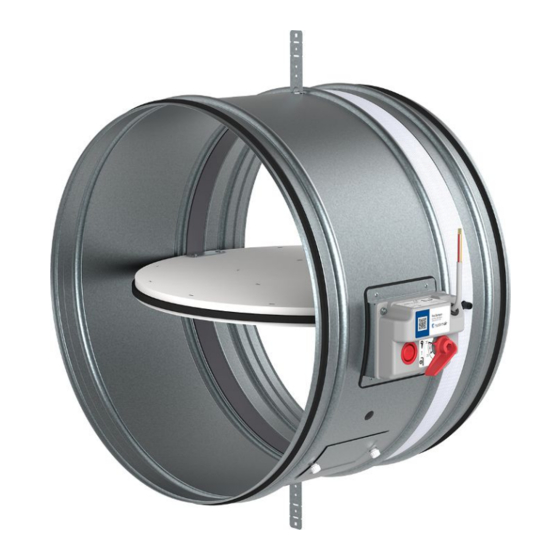
- Page 6 6/67 | FDR-3G Legend: P1 Blade P2 Casing P3 Manually operated activation mechanism (H0;H...) P4 Actuator operated activation mechanism (B...;G...) P5 Inspection lid P6 Thermoelectric fuse (BAT72;TA-72) P7 Supply and communication unit (BKN230-24;FS-UFC24-2) P8 Bendable hanger P9 Release and test button...
-
Page 7: Technical Parameters
7/67 | FDR-3G Technical Parameters Durability test • 50 cycles/manually operated activation mechanism – with no change of the required properties • 10000 + 100 + 100 cycles/actuator operated activation mechanism – with no change of the required properties Fire testing pressure... - Page 8 8/67 | FDR-3G Conformity with EC directives 2006/42/EC Machinery Directive 2014/35/EU Low Voltage Directive 2014/30/EU Electromagnetic Compatibility Directive Driving actuator types Belimo: BLF230-T, BLF24-T, BFL24-SR-T, BF230-T, BF24-T, BF24-SR-T, BFN230-T, BFN24-T, BFN24-T, BFL230-T, BFL24- T, BFL24-SR-T (also with connection possibilities with acronyms ST, W)
- Page 9 9/67 | FDR-3G Assessed Performance - FDR-3G 19 CE 1396 Systemair Production a.s. Hlavná 371, 900 43 Kalinkovo, Slovakia 1396-CPR-0162, FDR-3G (valid for subgroups: …EX, …KS, …OF) EN 15650 : 2010 Circular fire dampers Nominal activation conditions/sensitivity - Pass • sensing element load bearing capacity •...
-
Page 10: Diagrams
10/67 | FDR-3G Diagrams The pressure drop and A-weighted total discharged sound power level depend on the nominal diameter of the damper and air flow volume at different duct pressures. The type of activation does not influences the airflow parameter, therefore only one activation type is shown in the diagrams. - Page 11 11/67 | FDR-3G FDR-3G-...-H0 FDR-3G-...-H0 Pressure drop & A-weighted sound power level in dB(A) Pressure drop & A-weighted sound power level in dB(A) 1000 1000 2000 Size: 400 Size: 560 Size: 630 Size: 450 Size: 500 Size: 710 2000 3000 5000 m³/h...
- Page 12 12/67 | FDR-3G Dimensions DN 100 up to DN 630 Free area DN (mm) 100 125 140 150 160 180 200 225 250 280 315 355 400 450 500 560 630 0,003 0,007 0,009 0,011 0,013 0,018 0,023 0,031 0,039 0,050 0,065 0,085 0,110 0,138 0,173 0,220 0,283...
- Page 13 13/67 | FDR-3G DN 710 up to DN 1000 Free area DN (mm) 1000 0,357 0,459 0,587 0,731 Dimensions Note: 3) Inclusive bearing Overhangs DN (mm) 1000 (mm) (mm) Weights DN (mm) (kg ±5%) 1000 H0, H... 33,5 39,4 46,5 54,2 B..., G...
-
Page 14: Ordering Code
14/67 | FDR-3G Ordering Code Dimension, øDN (from 100 mm up to 1000 mm) B - Type of Activation (H0 up to G24T-SR) H0 - Manual crank, no switches H2 - Manual crank, 2 switches 230V AC or 24V AC/DC... - Page 15 15/67 | FDR-3G Inspection opening positions (Removable mechanism is available for all sizes): DN ≤ ø 150 No inspection opening. Inspection possible through removable mechanism or additional inspection opening must be added to the conecting duct. ø 160 ≤ DN ≤ ø225 Standardardly in position: L;...
- Page 16 16/67 | FDR-3G Installation Methods EI 60 (v i ↔ o) S FDR-3G EI 90 (v i ↔ o) S DN100 ... DN1000 360° 1 Wet EI 120 (v i ↔ o) S EI 60 (v i ↔ o) S FDR-3G DN100 ...
- Page 17 Information about installation, maintenance and operation is available in the “Handbook_FDR-3G” document or more can be found at design.systemair.com. Installation rules • The duct connected to the fire damper must be supported or hung in such a way that the damper does not carry its weight.
-
Page 18: Installation
18/67 | FDR-3G Wet Installation Using Plaster/Mortar/Concrete Filling 1. The supporting construction opening must be prepared as depicted. Opening surfaces must be even and cleaned off. The flexible wall opening must be reinforced as per the standards for plasterboard walls. The opening dimensions are driven by the nominal dimensions of the damper with added clearance. - Page 19 19/67 | FDR-3G...
- Page 20 20/67 | FDR-3G...
- Page 21 21/67 | FDR-3G Legend F1 Screw ≥ 5,5 DIN7981 or suitable wall plug and screw size 6. F2 Plaster/mortar/concrete filling 1 Fire damper (actuator side) 2 Bendable hanger 3 Concrete/masonry/cellular concrete wall or ceiling 4 Flexible (plasterboard) wall 4a 2 layers of plasterboard fireproof plate type F, EN 520 4b Vertical CW –...
- Page 22 22/67 | FDR-3G Dry Installation Using Mineral Wool and Cover Boards 1. The supporting construction opening must be prepared as depicted. Opening surfaces must be even and cleaned off. The flexible wall opening must be reinforced as per the standards for plasterboard walls. The opening dimensions are driven by the nominal dimensions of the damper with added clearance.
- Page 23 23/67 | FDR-3G...
- Page 24 24/67 | FDR-3G...
- Page 25 25/67 | FDR-3G Legend F1 Screw ≥ 5,5 DIN7981 or suitable wall plug and screw size 6. F3 Mineral wool filling (min. 50 kg/m3) F4 Fire resistive coating, e.g. Promastop-CC/Promat A1 Cover board CBR-FD (accessory) obligatory 1 Fire damper (actuator side)
- Page 26 26/67 | FDR-3G Soft installation Installation in a Soft Crossing with fire-resistive coating With this installation we recommend using flexible connection (see accessory FCR) due thermal expansion of connected ducts during fire. Install the compensator so, that the flexible part has a minimum distance of 50 mm from the edge of a damper‘s blade in open position.
- Page 27 27/67 | FDR-3G...
- Page 28 28/67 | FDR-3G...
- Page 29 29/67 | FDR-3G Legend F1 Screw ≥ 5,5 DIN7981 or suitable wall plug and screw size 6. F5 Mineral wool segment (minimum 150 kg/m3). F6 Layer of fire resistive coating (Promastop-CC/Promat) at least 2 mm thick for exposed surfaces. 1 Fire damper (actuator side)
- Page 30 30/67 | FDR-3G Hilti Installation Filling made only from Hilti foam With this installation we recommend using flexible connection (see accessory FCR) due thermal expansion of connected ducts during fire. Install the compensator so, that the flexible part has a minimum distance of 50 mm from the edge of a damper‘s blade in open position.
- Page 31 31/67 | FDR-3G...
- Page 32 32/67 | FDR-3G Legend F1 Screw ≥ 5,5 e.g. DIN7981 or suitable wall plug and screw size 6. F17 Foam CFS-F FX/HILTI. 1 Fire damper (actuator side) 2 Bendable hanger 3 Concrete/masonry/cellular concrete wall or ceiling 4 Flexible (plasterboard) wall 4a 2 layers of plasterboard fireproof plate type F, EN 520 4b Vertical CW –...
- Page 33 33/67 | FDR-3G Notes: ve Vertical (wall) 1) Smaller distances – maximum resistivity EI90 ( ve i<->o ) S...
- Page 34 34/67 | FDR-3G ON & OUT of the wall installation, EI90S Using 2 layers of Mineral Wool TIP: The duct-wall cavity filling can be also replaced by plaster/mortar/concrete (F2) as a replacement of filling (F9), then the coating (F10) is not needed for the cavity filling.
- Page 35 35/67 | FDR-3G...
- Page 36 36/67 | FDR-3G...
- Page 37 37/67 | FDR-3G Legend F9 Mineral wool segment (min. 66 kg/m3) - in a wall F10 Layer of fire resistive coating (BSF/ISOVER) at least 2 mm thick for exposed surfaces F11 Sheet metal belt 40 × 2 mm bent into an L shape of 35 and 160 mm...
- Page 38 38/67 | FDR-3G ON & OUT of the wall installation, EI60S Using 1 layer of Mineral Wool TIP: The duct-wall cavity filling can be also replaced by plaster/mortar/concrete (F2) as a replacement of filling (F9), then the coating (F10) is not needed for the cavity filling.
- Page 39 39/67 | FDR-3G...
- Page 40 40/67 | FDR-3G...
- Page 41 41/67 | FDR-3G Legend F9 Mineral wool segment (min. 66 kg/m3) - in a wall F10 Layer of fire resistive coating (BSF/ISOVER) at least 2 mm thick for exposed surfaces 1 Fire damper (actuator side) 3 Concrete/masonry/brick/cellular concrete wall or ceiling...
- Page 42 42/67 | FDR-3G Electrical Connections DN (mm) B230T/6,5 VA/BFL230-T B230T/10 VA/ BFN230-T B230T/11 VA/BF230-T B24T/4 VA/BFL24-T B24T/6 VA/BFN24-T B24T/10 VA/BF24-T B24T-W/4 VA/BFL24-T-ST B24T-W/6 VA/BFN24-T-ST B24T-W/10 VA/BF24-T-ST BST0/11 VA/BFL24-T-ST + BKN230-24 BST0/11 VA/BFN24-T-ST + BKN230-24 BST0/11 VA/BF24-T-ST + BKN230-24 B24T-SR / 6,5 VA / BFL24-T-SR...
- Page 43 43/67 | FDR-3G Type of activation H2 IMPORTANT: Risk of electric shock!Switch off the power supply before working on any electrical equipment.Only qualified electricians are allowed to work on the electrical system. Microswitch:Power Supply: 125/250V AC or 12/24V DCElectric Parameters: 3A NOTES: •...
-
Page 44: Electrical Parameters
44/67 | FDR-3G Type of activation H5-2 IMPORTANT: Risk of electric shock! Switch off the power supply before working on any electrical equipment. Only qualified electricians are allowed to work on the electrical system. Microswitch: Power Supply: 125/250V AC or 12/24V DC... - Page 45 45/67 | FDR-3G Type of activation H6-2 IMPORTANT: Risk of electric shock! Switch off the power supply before working on any electrical equipment. Only qualified electricians are allowed to work on the electrical system. Microswitch: Power Supply: 125/250V AC or 12/24V DC...
- Page 46 46/67 | FDR-3G Type of activation B230T IMPORTANT: Risk of electric shock! Switch off the power supply before working on any electrical equipment. Only qualified electricians are allowed to work on the electrical system. Actuator power supply: 230V AC, 50/60 Hz NOTES: •...
- Page 47 47/67 | FDR-3G Type of activation G230T IMPORTANT: Risk of electric shock! Switch off the power supply before working on any electrical equipment. Only qualified electricians are allowed to work on the electrical system. Actuator power supply: 230V AC, 50/60 Hz NOTES: •...
- Page 48 48/67 | FDR-3G Type of activation B24T IMPORTANT: Risk of electric shock! Switch off the power supply before working on any electrical equipment. Only qualified electricians are allowed to work on the electrical system. Actuator power supply: AC (50/60 Hz)/DC 24 V NOTES: •...
- Page 49 49/67 | FDR-3G Type of activation G24T IMPORTANT: Risk of electric shock! Switch off the power supply before working on any electrical equipment. Only qualified electricians are allowed to work on the electrical system. Actuator power supply: AC (50/60 Hz)/DC 24 V NOTES: •...
- Page 50 50/67 | FDR-3G Type of activation B24T-W IMPORTANT: Risk of electric shock! Switch off the power supply before working on any electrical equipment. Only qualified electricians are allowed to work on the electrical system. This type of activation is with provided cable connectors for the supply and communication unit (communication unit not part of the mechanism).
- Page 51 51/67 | FDR-3G Type of activation G24T-W IMPORTANT: Risk of electric shock! Switch off the power supply before working on any electrical equipment. Only qualified electricians are allowed to work on the electrical system. This type of activation is with provided cable connectors for the supply and communication unit (communication unit not part of the mechanism).
- Page 52 52/67 | FDR-3G Type of activation B24T-SR IMPORTANT: Risk of electric shock! Switch off the power supply before working on any electrical equipment. Only qualified electricians are allowed to work on the electrical system. Actuator power supply: AC (50/60 Hz)/DC 24 V NOTES: •...
- Page 53 53/67 | FDR-3G Type of activation G24T-SR IMPORTANT: Risk of electric shock! Switch off the power supply before working on any electrical equipment. Only qualified electricians are allowed to work on the electrical system. Actuator power supply: AC (50/60 Hz)/DC 24 V NOTES: •...
- Page 54 54/67 | FDR-3G Type of activation BST0 IMPORTANT: Risk of electric shock! Switch off the power supply before working on any electrical equipment. Only qualified electricians are allowed to work on the electrical system. This type of activation is with a Belimo supply and communication unit BKN230-24 (other communication units on demand).
- Page 55 55/67 | FDR-3G 3 - 6-pin connector: damper actuator (position limit switches) 4 - Connecting terminals: • 1 – 2 Jumper factory-fitted. Can be removed if necessary to be replaced by a thermoelectric trip (the safety function will be triggered if terminals 1 and 2 are not linked).
- Page 56 56/67 | FDR-3G Type of activation GST0 IMPORTANT: Risk of electric shock! Switch off the power supply before working on any electrical equipment. Only qualified electricians are allowed to work on the electrical system. This type of activation is with a Gruner supply and communication unit fs-UFC24-2 (other communication units on demand).
- Page 57 57/67 | FDR-3G Legend A1, A2 Analog Application; Digital input for manual override can be selected via bus as „Normally Open“ (= standard open) or „Normally Closed“ (= standard closed) Default: „Normally Open“ B Position of line termination 120 ohm if FS-UFC24-2 is last Modbus or BACnet device in line C RS-485 Coms;...
- Page 58 58/67 | FDR-3G Type of activation BST1 IMPORTANT: Danger of electric shock! Parallel circuits, i.e. a smoke detector on multiple slave devices are not allowed! Switch off the power supply before working on any electrical equipment. Allow only qualified electricians to work on the electrical system.
- Page 59 59/67 | FDR-3G T - Test button: This allows the simple function test on site of the damper. The button operation causes an error message at the control device which must be reset. X2 - 2-pin spring terminal: 1/2 - connection for SLC two-wire line, wires interchangeable. Maximum cable lengths can be calculated with the SLC Planning Tool.
- Page 60 60/67 | FDR-3G Type of activation BST2 IMPORTANT: Danger of electric shock! Switch off the power supply before working on any electrical equipment. Allow only qualified electricians to work on the electrical system. Actuator power supply via fitted communication unit: DC 24 V NOTES: •...
- Page 61 61/67 | FDR-3G 5 - Parametrization: DIL switch • A1:Baud rate • A2:Parity • A3: Termination (on with 150 Ω) • A4: Bus: BACnet (ON) or Modbus (OFF) • B:Modbus address 6 - LEDs status indication of actuator LED colour| LED state | Status...
- Page 62 62/67 | FDR-3G Type of activation BST3 IMPORTANT: Danger of electric shock! Switch off the power supply before working on any electrical equipment. Allow only qualified electricians to work on the electrical system. Actuator power supply via fitted communication unit: DC 24 V NOTES: •...
- Page 63 63/67 | FDR-3G BKN230-24-C-MP 1 2 3 4 5 6 7 Legend T - Button for test and address. 1 - Power supply: cable and plug, AC 230 V 2 - 3-pin connector: damper actuator (DC 24 V) 3 - 6-pin connector: damper actuator (position limit switches) 4 - 2-pin connector: BAT…...
- Page 64 64/67 | FDR-3G Type of activation BST10 IMPORTANT: Danger of electric shock! The BKN230-24-PL may only be used with a designated master (e.g. BKS64-PL). Switch off the power supply before working on any electrical equipment. Allow only qualified electricians to work on the electrical system.
-
Page 65: Operation Manual
65/67 | FDR-3G Operation Manual Warning To avoid injury, make sure to wear gloves and keep the blades movement area clear while manipulating with the damper.NEVER OPEN THE INSPECTION LID WHEN THERE IS AIR FLOWING IN THE DUCT CONNECTED TO THE FIRE DAMPER! - Page 66 66/67 | FDR-3G Recommended Inspection Steps According to the EN 15 650: 1.Damper identification2.Date of inspection3.Inspecting electric connection of the activation mechanism (where applicable)4.Inspecting damper for cleanliness and possible need for cleaning (where needed)5.Inspecting blade and sealing condition, possible correction and logging (where needed)6.Inspecting proper fire damper closure7.Inspecting damper functionality –...
- Page 67 Systemair DESIGN • 2022-07-11 • Handbook_FDR_3G_en-GB • Original instructions...
Need help?
Do you have a question about the FDR-3G and is the answer not in the manual?
Questions and answers