Table of Contents
Advertisement
Available languages
Available languages
Quick Links
READ AND SAVE THESE INSTRUCTIONS
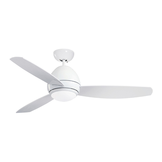
CURVA LED OUTDOOR
44" & 52" Wet Location Ceiling Fan
44" Model Numbers
CF244LGRT00
Graphite
CF244LORB00
Oil Rubbed Bronze
CF244LWW00
Appliance White
Net Weight:
Questions, problems, missing parts: Before returning to the store call
Emerson Electric Customer Service - 8 a.m. - 6 p.m., Eastern, Monday-Friday
Part No. F40BP75370000
Revision: 171110
Owner's Manual
18.3
Lbs.
1-800-654-3545
www.emersonfans.com
52" Model Numbers
CF252LGRT00
Graphite
CF252LORB00
Oil Rubbed Bronze
CF252LWW00
Appliance White
19.2
Net Weight:
Lbs.
• Español - página 29
• Français - page 57
Form No. BP7537
U.L. Model No.: CF244L & CF252L
Advertisement
Chapters
Table of Contents

Subscribe to Our Youtube Channel
Related Manuals for Emerson CURVA CF252LGRT00


Summary of Contents for Emerson CURVA CF252LGRT00
- Page 1 Lbs. Net Weight: Lbs. Questions, problems, missing parts: Before returning to the store call Emerson Electric Customer Service - 8 a.m. - 6 p.m., Eastern, Monday-Friday • Español - página 29 • Français - page 57 Part No. F40BP75370000 Form No. BP7537...
-
Page 2: Table Of Contents
UC8013R, manufactured by Rhine Electric Co., Ltd. 1. To avoid possible shock, be sure electricity is turned off To avoid fire, shock or injury, do not use an Emerson or at the fuse box before wiring, and do not operate fan any other brand of control not specifically approved for without blades. -
Page 3: Unpacking Instructions
1. Unpacking Instructions PACKAGE CONTENTS HARDWARE CONTENTS Part Wire Connectors, 12 ga. Description Quantity M5 x 16 mm Flange Head Blade Screws M4 x 10 mm Pan Head Screw for Lower Housing/LED Light Fixture Assembly (spare) Clevis Pin Hairpin Clip Threaded Stud, #8-32 x 1/1-4”... -
Page 4: Electrical Requirements
This Manual Is Designed to Make it as Easy as Possible for You to Assemble, Install, Operate and Maintain Your Ceiling Fan Tools Needed for Assembly Your Emerson ceiling fan comes supplied with a Fan/Light Remote Control which consists of a receiver mounted One Phillips Head Screwdriver One Stepladder inside the ceiling cover of the fan motor housing. -
Page 5: Ceiling Fan Assembly
3. Ceiling Fan Assembly M5 x 16 mm FLANGE HEAD BLADE SCREWS (3 per blade) FAN BLADE SLIDE FAN BLADE INTO BLADE CENTER SLOT FAN MOTOR ASSEMBLY WARNING BLADE SLOT To reduce the risk of personal injury, do not bend the Figure 1 blades during installation, balancing the blades or cleaning the fan. - Page 6 3. Ceiling Fan Assembly (Continued) GREEN GROUND WIRE 4.5" DOWNROD HANGER BALL PHILLIPS HEAD SET SCREW (LOOSENED) Figure 3 THREE 80" MOTOR LEADS (UNTWISTED) 4.5" DOWNROD Figure 4 U.L. Model No.: CF244L & CF252L...
- Page 7 3. Ceiling Fan Assembly (Continued) DOWNROD LOOSEN PHILLIPS HEAD SET MOTOR SCREWS (2) COUPLER Figure 5 HAIRPIN CLIP CLEVIS MOTOR COUPLER HAIRPIN CLEVIS CLIP WARNING It is critical that the clevis pin in the motor coupler is properly installed. Failure to verify that the pin is properly installed could result in the fan falling.
- Page 8 3. Ceiling Fan Assembly (Continued) Make sure the Grommet is properly installed in the Coupler Cover, then slide the Coupler Cover on the Downrod until it rests on the Motor Housing (Figure 8). DOWNROD GROMMET COUPLER COVER Figure 8 Place the Ceiling Cover over the Downrod (Figure 9). Be sure that the Ceiling Cover and the Coupler Cover are both oriented correctly (Figure 9).
- Page 9 WARNING CEILING The fan must be hung with at least 7' of clearance from floor to blades (Figure 11). WARNING Turning off wall switch is not sufficient. To avoid possible electrical shock, be sure electricity is turned off at the LEAST main fuse box before wiring.
-
Page 10: How To Hang Your Ceiling Fan
Securely attach the Hanger Bracket to the Outlet Box using the two Screws supplied with the Outlet Box. (Figure 13). OUTLET TWO SCREWS SUPPLIED WITH OUTLET BOX HANGER BRACKET Figure 13 Carefully lift the fan and seat the Hanger Ball/ NOTE: CEILING COVER, SUPPLY WIRES AND FAN WIRES OMITTED FOR CLARITY. -
Page 11: How To Wire Your Ceiling Fan
5. How to Wire Your Ceiling Fan If you feel that you do not have enough electrical CAUTION: To reduce the risk of electrical shock, wiring knowledge or experience, have your fan disconnect the electrical supply circuit before installed by a licensed electrician. installing the fan, light kit or receiver. - Page 12 5. How to Wire Your Ceiling Fan (Continued) Securely connect the Supply White Wire (neutral) to the Receiver White Wire (AC IN N) / (TO MOTOR N) and Fan Motor White Wire (neutral) using a Wire Connector SUPPLY (supplied) (Figure 17). WHITE WIRE FAN MOTOR WHITE WIRE...
- Page 13 5. How to Wire Your Ceiling Fan (Continued) FAN MOTOR Securely connect the Fan Motor Black Wire to the BLACK WIRE Receiver Black Wire (TO MOTOR L) using a Wire Connector (supplied) (Figure 20). RECEIVER BLACK WIRE Figure 20 WARNING Check to see that all connections are tight, including RECEIVER ground, and that no bare wire is visible at the wire...
- Page 14 5. How to Wire Your Ceiling Fan (Continued) Screw the two Threaded Studs (supplied) into the tapped holes in the Hanger Bracket (Figure 22). THREADED STUDS (2) Figure 22 Lift the Ceiling Cover up to the Threaded Studs and turn until Studs protrude through the holes in the Ceiling Cover (Figure 23).
- Page 15 6. Final Assembly FAN MOTOR ASSEMBLY WHITE WIRE FAN MOTOR ASSEMBLY BLUE WIRE LED LIGHT FIXTURE ASSEMBLY BLACK WIRE LED LIGHT FIXTURE ASSEMBLY WHITE WIRE LED LIGHT FIXTURE ASSEMBLY Figure 24 Remove one of the three M4 x 10 mm Pan Head Screws LOWER in the Lower Housing and loosen the remaining two HOUSING...
-
Page 16: Final Assembly
6. Final Assembly (Continued) Rotate the LED Light Fixture Assembly clockwise on the LOWER Lower Housing by engaging the two loosened screws onto HOUSING the key hole slots (Figure 26). Secure the LED Light Fixture Assembly by tightening the two M4 x 10 mm Pan Head Screws. Reinstall the M4 x 10 mm Pan Head Screw that was previously removed. -
Page 17: Optional Installation Of No-Light Cover
7. Optional Installation of No-Light Cover NOTE: To use the No-Light Cover, the LED Light Fixture Assembly MUST NOT Be Installed, or the LED Light Fixture Assembly MUST Be Removed. WARNING Turning off wall switch is not sufficient. To avoid possible electrical shock, be sure electricity is turned off at the main fuse box before wiring. - Page 18 7. Optional Installation of No-Light Cover (Continued) Disconnect the LED Light Fixture Assembly wire terminals from the Fan Motor Assembly wire terminals. (Figure 30). Store the LED Light Fixture Assembly in a safe location for future installation. Tuck the Fan Motor Assembly wires and connectors into the Lower Housing prior to assembling the No-Light Cover.
-
Page 19: Remote Control Procedures
8. Remote Control Procedures 8.1: Preset Memory Feature Your Emerson receiver is equipped with a preset memory When the switch is turned back ON the light and fan will feature. If the AC supply to the receiver is powered resume operation as they we re prior to the switch being through a wall switch, when the switch is turned OFF, turned OFF. - Page 20 8. Remote Control Procedures (Continued) Your Emerson Ceiling Fan/Light Remote Control consists of hand-held Transmitter and a Receiver which is mounted under the Fan Ceiling Cover. POWER INDICATOR When power is restored, push and hold the fan OFF LIGHT button ( ) for 3 to 5 seconds to set the code in the Receiver (Figure 34).
- Page 21 8. Remote Control Procedures (Continued) To turn the Downlight on, press and release the ( button. The Light will turn on at the light intensity previously selected (Figure 36). POWER INDICATOR LIGHT To vary the intensity of the Light, hold the ( ) button down until the desired light intensity is reached, then release the button (Figure 36).
-
Page 22: Maintenance
Emerson Electric Co. Substitution of parts or accessories not designated • Slope Ceiling Kit for use with this product by Emerson Electric Co. could result in personal injury or property damage. WARNING The use of any other control not specifically approved for this fan could result in fire, shock and personal injury. -
Page 23: Troubleshooting
11. Troubleshooting WARNING FOR YOUR OWN SAFETY TURN OFF POWER AT FUSE BOX OR CIRCUIT BREAKER BEFORE TROUBLESHOOTING YOUR FAN. TROUBLE PROBABLE CAUSE SUGGESTED REMEDY 1. Fan will not start. 1. Fuse or circuit breaker blown. 1. Check main and branch circuit fuses or circuit breakers. WARNING Make sure main power is turned OFF. -
Page 24: Repair Parts
12. Repair Parts PARTS BAG 10 - 52" 11- 44" U.L. Model No.: CF244L & CF252L... - Page 25 12. Repair Parts Listing Wet Part Numbers Model No. Model No. Model No. Model No. Model No. Model No. Description CF244LGRT00 CF252LGRT00 CF244LWW00 CF252LWW00 CF244LORB00 CF252LORB00 Hanger Pack Consisting of: 761655-102 761655-102 761655-14 761655-14 761655-32 761655-32 Hanger Bracket Assembly — —...
-
Page 26: Energy Efficient Use Of Ceiling Fan
Remember feet above the floor for optimal airflow. Consult your to adjust your thermostat when using your ceiling fan - Emerson Retailer for optional mounting accessories. additional energy and dollar savings could be realized with this simple step! Turn Off When Not in the Room. -
Page 27: Ceiling Fan Limited Warranty
What We Will Do To Correct Problems: If the defect is covered by this limited warranty, Emerson will repair or replace the applicable Emerson Ceiling Fan Product at no charge to You. If repair of the Emerson Ceiling Fan Product is not practical or possible within a reasonable time and no replacement Emerson Ceiling Fan Product can be provided, Emerson will refund You the actual purchase price of Your Emerson Ceiling Fan Product. - Page 28 The date code of this fan may be found on the box, stamped in ink on a white label. You should record this data above and keep it in a safe place for future use. Air Comfort Products DIVISION OF EmErSON ElEctrIc cO. 8100 W. Florissant • St. louis, mO 63136 Questions, problems, missing parts: Before returning to the store call Emerson Electric Customer Service 8 a.m.
-
Page 29: Spanish
19,2 Peso neto: Peso neto: Preguntas, problemas, piezas faltantes: Antes de devolver el producto a la tienda, llame al Servicio al Cliente de Emerson Electric 8 a.m. a 6 p.m., Hora del Este, lunes a viernes 1-800-654-3545 • Français – page 57 No. - Page 30 Para evitar incendios, descargas eléctricas o lesiones, no utilice un 1. Para evitar posibles descargas eléctricas, asegúrese de que la control Emerson o de cualquier otra marca que no esté aprobado electricidad esté desconectada en la caja de fusibles antes de específicamente para este ventilador.
- Page 31 Emerson Electric Co. para utilizarse con Soporte de suspensión este producto. La sustitución con piezas o accesorios no diseñados por Emerson Electric Co. para utilizarse con este Ensamblaje de esfera de suspensión/varilla descendente producto podría causar lesiones corporales o daños materiales.
- Page 32 Emerson Electric ADVERTENCIA suministrado con el ventilador.
- Page 33 3. Ensamblaje del ventilador de techo TORNILLOS CON CABEZA M5 x 16 mm FLANGE HEAD PALETA DEL DE PESTAÑA PARA PALETA BLADE SCREWS (3 per blade) FAN BLADE Ponga el ensamblaje del motor del ventilador en posición invertida VENTILADOR M5 x 16 mm (3 por paleta) en preparación para el montaje de las tres paletas del ventilador.
- Page 34 3. Ensamblaje del ventilador de techo (continuación) GREEN GROUND WIRE CABLE VERDE DE CONEXIÓN Voltee cuidadosamente el ventilador de techo parcialmente A TIERRA ensamblado de manera que quede al derecho y coloque de forma PASADOR segura el ventilador en la espuma de estireno de embalaje en preparación para el ensamblaje final.
- Page 35 3. Ensamblaje del ventilador de techo (continuación) VARILLA DOWNROD DESCENDENTE LOOSEN PHILLIPS AFLOJE LOS TORNILLOS HEAD SET DE AJUSTE DE CABEZA MOTOR SCREWS (2) ACOPLAMIENTO PHILLIPS (2) COUPLER DEL MOTOR Figura 5 Alinee los agujeros para pasador de horquilla ubicados en la varilla descen dente con los agujeros ubicados en el acoplamiento del motor.
- Page 36 3. Ensamblaje del ventilador de techo (continuación) Asegúrese de que el aro de refuerzo esté instalado apropiada - VARILLA ARO DE mente sobre la cubierta del acoplador y luego deslice dicha DOWNROD DESCENDENTE GROMMET REFUERZO cubierta sobre la varilla descendente hasta que descanse sobre la CUBIERTA DEL carcasa del motor (Figura 8).
- Page 37 4. Cómo colgar su ventilador de techo ADVERTENCIA CEILING TECHO El ventilador se debe colgar con por lo menos 7 pies de holgura desde el piso hasta las paletas (Figura 11). ADVERTENCIA No basta con poner el interruptor de pared en la posición de POR LO LEAST apagado.
- Page 38 4. Cómo colgar su ventilador de techo (continuación) Sujete firmemente el soporte de suspensión a la caja de toma - corriente utilizando los dos tornillos suministrados con dicha caja (Figura 13). OUTLET CAJA DE TOMA CORRIENTE DOS TORNILLOS TWO SCREWS SUMINISTRADOS SUPPLIED WITH CON LA CAJA DE...
- Page 39 5. Cómo cablear su ventilador de techo PRECAUCIÓN: Para reducir el riesgo de descargas eléctricas, Si le parece que no tiene suficientes conocimientos o experiencia desconecte el circuito de suministro eléctrico antes de instalar el en cableado eléctrico, haga que un electricista con licencia ventilador, el kit de iluminación o el receptor.
- Page 40 5. Cómo cablear su ventilador de techo (continuación) Conecte firmemente el cable blanco de suministro (neutro) al cable blanco del receptor (ENTRADA CA N) / (AL MOTOR N) y el cable SUPPLY CABLE BLANCO blanco del motor del ventilador (neutro) utilizando un conector de WHITE WIRE DE SUMINISTRO cables (suministrado) (Figura 17).
- Page 41 5. Cómo cablear su ventilador de techo (continuación) FAN MOTOR CABLE NEGRO BLACK WIRE DEL MOTOR DEL Conecte firmemente el cable negro del motor del ventilador al VENTILADOR cable negro del receptor (AL MOTOR V), utilizando un conector de cables (suministrado) (Figura 20). RECEIVER CABLE NEGRO BLACK WIRE...
- Page 42 5. Cómo cablear su ventilador de techo (continuación) Enrosque los dos espárragos roscados (suminis trados) en los agujeros roscados ubicados en el soporte de suspensión (Figura 22). THREADED ESPÁRRAGOS STUDS (2) ROSCADOS (2) Figura 22 Levante la cubierta del techo hasta los espárragos roscados y gírela hasta que dichos espárragos sobresalgan a través de los agujeros ubicados en la cubierta del techo (Figura 23).
- Page 43 6. Ensamblaje final NOTA: Si está instalando el ventilador de techo sin el ensamblaje del accesorio de iluminación LED, vaya a la Sección 7, Instalación opcional de la cubierta sin luz, Paso 7.4. Conecte firmemente el terminal del cable blanco del ensamblaje del accesorio de iluminación LED al terminal del cable blanco del ensamblaje del motor del ventilador (Figura 24).
- Page 44 6. Ensamblaje final (continuación) Rote el ensamblaje del accesorio de iluminación LED en el sentido CARCASA LOWER INFERIOR de las agujas del reloj sobre la carcasa inferior, acoplando los dos HOUSING tornillos aflojados en las ranuras de bocallave (Figura 26). Sujete firmemente el ensamblaje del accesorio de iluminación LED apretando los dos tornillos de cabeza troncocónica M4 x 10 mm.
- Page 45 7. Instalación opcional de la cubierta sin luz NOTA: Para utilizar la cubierta sin luz, el ensamblaje del accesorio de iluminación LED NO DEBE estar instalado o dicho ensamblaje DEBE ser retirado. ADVERTENCIA No basta con poner el interruptor de pared en la posición de apagado.
- Page 46 7. Instalación opcional de la cubierta sin luz (continuación) Desconecte los terminales de los cables del ensamblaje del accesorio de iluminación LED separándolos de los terminales de los cables del ensamblaje del motor del ventilador (Figura 30). Guarde el ensamblaje del accesorio de iluminación LED en un lugar seguro para instalarlo en el futuro.
- Page 47 8.1: Función de memoria preestablecida Al poner el interruptor de vuelta en la posición de ENCENDIDO, la luz Su receptor Emerson está equipado con una función de memoria y el ventilador reanudarán su funcionamiento en la posición en la preestablecida. Si el suministro de CA al receptor se controla a que estaban antes de poner el interruptor en la posición de...
- Page 48 8. Procedimientos para el control remoto (continuación) Su control remoto del ventilador de techo y la luz Emerson consiste en un transmisor de mano y un receptor que se monta debajo de la POWER INDICATOR LUZ INDICADORA DE cubierta del techo del ventilador.
- Page 49 8. Procedimientos para el control remoto (continuación) Para encender la luz descendente, presione y suelte el botón ). La luz se encenderá con la intensidad seleccionada previamente (Figura 36). POWER INDICATOR LUZ INDICADORA DE LIGHT Para variar la intensidad de la luz, mantenga presionado el botón ALIMENTACIÓN ) hasta que se alcance la intensidad de la luz deseada y suelte el botón (Figura 36).
- Page 50 10. Accesorios ADVERTENCIA Vea a su distribuidor local de Emerson, visite www.emersonfans.com o consulte el Catálogo de ventiladores de techo Emerson acerca de estos accesorios: Este producto está diseñado para utilizar únicamente las piezas suministradas con este producto y/o los accesorios diseñados •...
- Page 51 11. Resolución de problemas ADVERTENCIA PARA SU PROPIA SEGURIDAD, DESCONECTE LA ALIMENTACIÓN ELÉCTRICA EN LA CAJA DE FUSIBLES O EL CORTACIRCUITO ANTES DE RESOLVER PROBLEMAS EN SU VENTILADOR PROBLEMA CAUSA PROBABLE REMEDIO SUGERIDO 1. El ventilador 1. Fusible o cortacircuito fundido. 1.
- Page 52 12. Piezas de repuesto PARTS BAG BOLSA DE PIEZAS 10 - 52" 11- 44" No. de modelo U.L.: CF244L y CF252L...
- Page 53 12. Lista de piezas de repuesto Números de pieza para lugares mojados No. de No. de modelo No. de modelo No. de modelo No. de modelo No. de modelo No. de modelo clave Descripción CF244LGRT00 CF252LGRT00 CF244LWW00 CF252LWW00 CF244LORB00 CF252LORB00 Paquete de suspensión que consiste en: 761655-102 761655-102...
- Page 54 óptima. fuerza el aire caliente que está cerca del techo a bajar al espacio Consulte a su minorista Emerson para informarse sobre los ocupado. Recuerde ajustar el termostato cuando utilice el ventilador accesorios de montaje opcionales.
- Page 55 Ventilador de Techo Emerson sigue estando bajo garantía, sírvase retener Su recibo u otro comprobante de compra y tener esa información al alcance de la mano cuando envíe su Producto de Ventilador de Techo Emerson a Su lugar de compra o cuando llame a Servicio al Cliente de Emerson. Si Usted llama a Servicio al Cliente de Emerson, antes de Su llamada esté preparado para dar todos los números de modelo mostrados en su Producto de Ventilador de Techo Emerson.
- Page 56 DIVISION OF EmErSON ElEctrIc cO. 8100 W. Florissant • St. louis, mO 63136 Preguntas, problemas, piezas faltantes: Antes de devolver el producto a la tienda, llame al Servicio al Cliente de Emerson Electric 8 a.m. a 6 p.m., Hora del Este, lunes a viernes +1-800-654-3545 www.emersonfans.com...
-
Page 57: French
Poids net : Poids net : Questions, problèmes, pièces manquantes : Avant de retourner un produit au magasin, veuillez téléphoner au Emerson Electric Customer Service 8h00 – 18h00 (HNE) du lundi au vendredi 1-800-654-3545 • Español – página 29 Pièce N° F40BP75370000 Formulaire N°... -
Page 58: Consignes De Sécurité
Pour éviter tout risque d’incendie, de choc électrique ou de blessure, d’effectuer le câblage, et ne mettez pas le ventilateur en marche n’utilisez pas de commande d’Emerson ou de toute autre marque qui sans avoir installé les pales. n’a pas été approuvée spécifiquement pour ce ventilateur. -
Page 59: Instructions Pour Le Déballage
Ce produit est conçu pour n’être utilisé qu’avec les pièces fournies avec celui-ci et/ou les accessoires conçus spécifiquement pour Verre emploi avec ce produit par Emerson Electric Co. Toute substitution Plaque de recouvrement en l’absence de pièces ou d’accessoires non conçus pour emploi avec ce produit de luminaire par Emerson Electric Co. -
Page 60: Alimentation Électrique
Ce mode d’emploi est conçu pour vous permettre d’assembler, d’installer, d’utiliser et d’entretenir votre ventilateur de plafond aussi facilement que possible Outils nécessaires pour le montage Votre ventilateur de plafond Emerson est fourni avec une télécommande de ventilateur/luminaire consistant en un récepteur monté à l’intérieur Un tournevis à pointe cruciforme Un escabeau de la monture de plafond du boîtier du moteur de ventilateur. -
Page 61: Assemblage Du Ventilateur De Plafond
3. Assemblage du ventilateur de plafond VIS M5 x 16 mm POUR LES BRIDES M5 x 16 mm FLANGE HEAD PALE DU DE FIXATION DES PALES (3 par pale) BLADE SCREWS (3 per blade) FAN BLADE VENTILATEUR Positionnez l’ensemble de moteur du ventilateur sens dessus dessous afin de vous préparer pour le montage des trois pales du ventilateur. - Page 62 3. Assemblage du ventilateur de plafond (suite) GREEN GROUND WIRE FIL DE MISE À LA TERRE VERT Faites tourner soigneusement le ventilateur de plafond partielle ment assemblé et placez-le délicatement dans la mousse de poly styrène pour terminer la dernière étape de l’installation du ventilateur. TIGE DE SUSPENSION Retirez la rotule de la tige de suspension en desserrant la vis de 4.5"...
- Page 63 3. Assemblage du ventilateur de plafond (suite) TIGE DE SUSPENSION DESCENDANTE DOWNROD LOOSEN PHILLIPS DESSERREZ LES VIS HEAD SET DE PRESSION À TÊTE MOTOR SCREWS (2) COUPLEUR CRUCIFORME (2) COUPLER DU MOTEUR Figure 5 Alignez les trous des axes à épaulement dans la tige de suspension descendante sur les trous du coupleur de moteur.
- Page 64 3. Assemblage du ventilateur de plafond (suite) Assurez-vous que l’œillet est installé correctement dans le cache du TIGE DE ŒILLET coupleur, puis faites glisser le cache du coupleur sur la tige de DOWNROD SUSPENSION GROMMET suspension descendante jusqu’à ce qu’il repose sur le boîtier du moteur DESCENDANTE (Figure 8).
-
Page 65: Comment Suspendre Votre Ventilateur De Plafond
4. Comment suspendre votre ventilateur de plafond AVERTISSEMENT CEILING PLAFOND Le ventilateur doit être suspendu de telle sorte que les pales se trouvent à au moins 7 pi (2 m) du sol (Figure 11). AVERTISSEMENT Éteindre l’interrupteur mural ne suffit pas. Pour éviter tout choc électrique éventuel, assurez-vous que l’alimentation électrique est AU MOINS LEAST... - Page 66 4. Comment suspendre votre ventilateur de plafond (suite) Attachez de façon sécurisée le support de fixation au boîtier de prises de courant à l’aide des deux vis fournies avec le boîtier de prises de courant (Figure 13). OUTLET BOÎTIER DE PRISES DE DEUX VIS COURANT...
-
Page 67: Comment Effectuer Le Câblage Pour Raccorder Votre Ventilateur De Plafond
5. Comment effectuer le câblage pour raccorder votre ventilateur de plafond MISE EN GARDE : Pour réduire le risque de choc électrique, Si vous pensez que vous n’avez pas d’expérience ou de con - naissances suffisantes en matière de câblage, demandez à un déconnectez le circuit d’alimentation électrique avant d’installer le électricien agréé... - Page 68 5. Comment effectuer le câblage pour raccorder votre ventilateur de plafond (suite) Connectez de façon sécurisée le fil blanc d’alimentation (neutre) au fil blanc du récepteur (AC IN N) / (TO MOTOR N) et au fil blanc du SUPPLY FIL BLANC moteur du ventilateur (neutre) en utilisant un capuchon de WHITE WIRE D’ALIMENTATION...
- Page 69 5. Comment effectuer le câblage pour raccorder votre ventilateur de plafond (suite) FAN MOTOR FIL NOIR DU MOTEUR DU BLACK WIRE Connectez de façon sécurisée le fil noir du moteur du ventilateur au fil VENTILATEUR noir du récepteur (TO MOTOR L) en utilisant un capuchon de connexion de fils (fourni) (Figure 20).
- Page 70 5. Comment effectuer le câblage pour raccorder votre ventilateur de plafond (suite) Vissez les deux goujons filetés de 1-1/4 po (fournis) à l’intérieur des trous taraudés du support de la tige de suspension descendante (Figure 22). THREADED GOUJON STUDS (2) FILETÉ...
- Page 71 6. Montage final REMARQUE : Si vous installez un ventilateur de plafond sans l’ensemble de luminaire à DEL, passez directement à la Section 7, Installation avec la plaque de recouvrement en option en l’absence de luminaire, Étape 7.4. Raccordez de façon sécurisée la borne du fil blanc de l’ensemble de luminaire à...
-
Page 72: Montage Final
6. Montage final (suite) Faites tourner l’ensemble de luminaire à DEL dans le sens des aiguilles LOWER BOÎTIER d’une montre sur le boîtier inférieur en engageant les deux vis HOUSING INFÉRIEUR desserrées dans les fentes en forme de trou de serrure (Figure 26). Sécurisez l’ensemble de luminaire à... -
Page 73: Installation Avec La Plaque De Recouvrement En Option En L'absence De Luminaire
7. Installation avec la plaque de recouvrement en option en l’absence de luminaire REMARQUE : Pour utilise la plaque de recouvrement en l’absence de luminaire l’ensemble de luminaire à DEL NE DOIT PAS avoir été installé, ou l’ensemble de luminaire à DEL DOIT être retiré. AVERTISSEMENT Il ne suffit pas d’appuyer sur le bouton de l’interrupteur mural. - Page 74 7. Installation avec la plaque de recouvrement en option en l’absence de luminaire (suite) Déconnectez les bornes des fils de l’ensemble de luminaire à DEL des bornes des fils de l’ensemble de moteur du ventilateur (Figure 30). Rangez l’ensemble de luminaire à DEL en lieu sûr en vue d’installation ultérieurement.
-
Page 75: Procédures Associées À La Télécommande
8.1 Fonction de mémoire préréglée Lorsque l’interrupteur sera activé de façon à remettre l’équipement sous Votre récepteur Emerson comporte une fonction de mémoire préréglée. tension (ON), le luminaire et le ventilateur se remettront en marche avec Si l’alimentation c.a. du récepteur provient d’un interrupteur mural, les mêmes paramètres de fonctionnement qu’au moment où... - Page 76 8. Procédures associées à la télécommande (suite) La télécommande de votre ventilateur de plafond/luminaire Emerson consiste en un émetteur tenu à la main et un récepteur qui est installé à POWER INDICATOR l’intérieur de la monture de plafond du ventilateur.
- Page 77 POWER INDICATOR VOYANT D’ALIMENTATION LIGHT ÉLECTRIQUE LIGHT INTENSITY BOUTON DE RÉGLAGE DE BUTTON L’INTENSITÉ LUMINEUSE Figure 36 8.7 Installation du support de rangement TO INSTALL BRACKET TO INSTALLATION DU SUPPORT WALL: COVER SUR LE MUR : CACHE Un support de rangement est fourni pour que vous puissiez y placer FAIRE GLISSER LE CACHE DU SLIDE THE COVER UP TO SUPPORT MURAL VERS LE HAUT...
-
Page 78: Maintenance
10. Accessoires AVERTISSEMENT Contactez votre revendeur local de produits Emerson, allez sur le site www.emersonfans.com ou consultez le catalogue des ventilateurs de plafond Emerson pour ces accessoires : Ce produit est conçu pour être utilisé uniquement avec les pièces qui sont fournies avec ce produit et/ou tous accessoires spécifi -... -
Page 79: Identification Des Causes Des Problèmes
11. Identification des causes des problèmes AVERTISSEMENT POUR VOTRE SÉCURITÉ, METTEZ LE COFFRET À FUSIBLES OU LE DISJONCTEUR HORS TENSION AVANT DE TENTER D’IDENTIFIER LES PROBLÈMES POUVANT AFFECTER VOTRE VENTILATEUR. PROBLÈME CAUSE PROBABLE SOLUTION PROPOSÉE 1. Il se peut qu’un fusible ait grillé ou que le disjoncteur 1. -
Page 80: Pièces De Rechange
15. Pièces de rechange PARTS BAG SAC DE PIÈCES 10 - 52" 11- 44" Modèle U.L. N° CF244L & CF252L... - Page 81 15. Nomenclature des pièces de rechange Numéros des pièces pour les endroits directement exposés à la pluie Modèle N° Modèle N° Modèle N° Modèle N° Modèle N° Modèle N° Réf. Description CF244LGRT00 CF252LGRT00 CF244LWW00 CF252LWW00 CF244LORB00 CF252LORB00 Paquet d’accessoires de suspension consistant en : 761655-102 761655-102...
-
Page 82: Utilisation Éco-Énergétique Des Ventilateurs De Plafond
énergétique et sur le plan financier grâce à ce ou 2,70 m) du sol pour une circulation de l’air optimale. Consultez votre simple geste ! revendeur Emerson pour obtenir des accessoires de montage optionnels. Éteignez le ventilateur lorsque vous sortez de la pièce. Les ventilateurs de plafond servent à... -
Page 83: Garantie Limitée Relative Aux Ventilateurs De Plafond
La présente garantie limitée est offerte par Air Comfort Products, une division d’Emerson Electric Co. (« Emerson », ou « notre », « nos » ou « nous ») à l’acheteur primitif (« vous », « votre » ou «... - Page 84 DIVISION OF EmErSON ElEctrIc cO. 8100 W. Florissant • St. louis, mO 63136 Questions, problèmes, pièces manquantes : Avant de retourner un produit au magasin, veuillez téléphoner au Service à la clientèle d’Emerson Electric 8h00 – 18h00 (HNE) du lundi au vendredi +1-800-654-3545 www.emersonfans.com Conservez ce mode d’emploi pour toute utilisation future.
Need help?
Do you have a question about the CURVA CF252LGRT00 and is the answer not in the manual?
Questions and answers