
Related Manuals for Emerson ODYSSEY CF2455BS00


Summary of Contents for Emerson ODYSSEY CF2455BS00
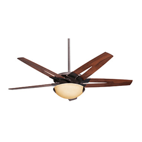
- Page 1 READ AND SAVE THESE INSTRUCTIONS ODYSSEY ® 54” Ceiling Fan Owner's Manual Model No. CF2455BS00 CF2455ORB00 CF2455PW00 26.0 Net Weight: Lbs. Part No. F40BP73370000 Form No. BP7337 U.L. Model No.: CF2455...
-
Page 2: Safety Instructions
WARNING: This product is designed to use only those parts supplied with this product and/or any accessories designated specifically for use this product by Emerson Electric Co. Substitution of parts or accessories not designated for use with this product by Emerson could result in personal injury or property damage. -
Page 3: Unpacking Instructions
Emerson Electric Co. Substitution of parts or accessories not designated for use with this product by Emerson Electric Co. could result in personal injury or property damage. 1. Open styrofoam unit containing fan. Remove upper and center sections of styrofoam unit. -
Page 4: Electrical Requirements
SW105 Receiver which mounts under the ceiling cover. This system allows you to regulate your ceiling fan speed, airflow direction, and light intensity. An optional Emerson Electric SR110 Remote Control may also be used. IMPORTANT: Your ceiling fan will not function... - Page 5 WARNING It is critical that the clevis pin in the motor coupling is properly installed and the setscrew securely tightened. Failure to verify that the pin and setscrew are properly installed could result in the fan falling. DOWNROD HAIRPIN CLIP...
- Page 6 LIGHT KIT PLATE ASSEMBLY SINGLE-PIN CONNECTOR Figure 8 19. Lift the fan assembly from the styrofoam and remove the center styrofoam section. Turn the fan SETSCREW assembly over and carefully position it on the upper styrofoam section so that the hanger COLLAR ball/downrod assembly is at the top (Figure 9).
-
Page 7: Your Ceiling Fan How To Hang
Failure to seat tab in groove could cause damage to electrical wires and possible shock or fire hazard. NOTE: CEILING COVER, SUPPL Y WIRES AND FAN WIRES OMITTED FOR CLARITY. Figure 13 To avoid possible fire or shock, do not pinch wires between the hanger ball/downrod assembly and the hanger bracket. -
Page 8: How To Wire Your Ceiling Fan
All wiring must be in accordance with National and Local codes and the ceiling fan must be properly grounded as a precaution against possible electrical shock. -
Page 9: Final Assembly
Do not operate fan until blades are in place. Noise and fan damage could result. 4. After connections have been made, separate the white and green wires from the black, blue and yellow wires. - Page 10 LIGHT KIT GLASS LIGHT KIT GLASS Figure 21 12. Your ceiling fan is now installed and wired and ready for use. LIGHT KIT TURN KNURLED KNOB GLASS SCREW SEVERAL TURNS...
- Page 11 The SW116 wall control transmits the command signals via radio waves to the SW105 receiver installed in the ceiling fan ceiling cover. The SW105 receiver is required for the SW116 wall control to function. Power for the SW116 wall control comes from the 12V battery, located in the wall control.
-
Page 12: Operating Your Ceiling Fan
Your SW116 Fan/Light Wall Control (Figure 25) has full control of your fan, lights, and airflow direction. 1.To set the desired fan speed, push the HI, MED, or LOW buttons to operate your fan on high, medium or low speed (See Figure 25). -
Page 13: Maintenance
Emerson. Substitution of parts or accessories not designated for use with this product by Emerson could result in personal injury or property damage. Trouble Shooting PROBABLE CAUSE 1. -
Page 14: Repair Parts
Repair Parts FAN OFF EMERSON... - Page 15 WHEN ORDERING REPAIR PARTS, ALWAYS GIVE THE FOLLOWING INFORMATION: • PART NUMBER • NAME OF ITEM The model number of your Fan will be found on a label attached to the top housing. For repair parts, phone 1-800-654-3545. Model No.
-
Page 16: Limited Warranty
You will be responsible for all insurance, freight or other transportation charges to our factory or authorized service center. Your Emerson Air Comfort Ceiling Fan should be properly packed to avoid damage in transit since we will not be responsible for any such damage.
Need help?
Do you have a question about the ODYSSEY CF2455BS00 and is the answer not in the manual?
Questions and answers