Table of Contents
Advertisement
READ AND SAVE THESE INSTRUCTIONS
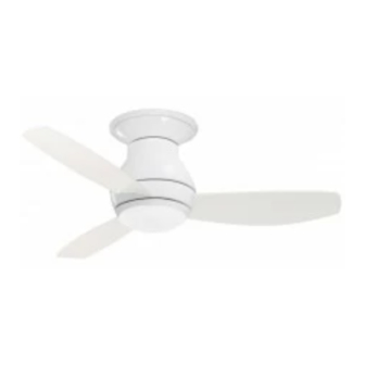
44" & 52" Damp & Wet Location
Snugger Ceiling Fan Owner's Manual
44" Model Numbers
for Damp Locations
CF144BS00
Brushed Steel
44" Model Numbers
for Wet Locations
CF144GRT00
Graphite
CF144ORB00
Oil Rubbed Bronze
CF144WW00
Appliance White
Net Weight:
Questions, problems, missing parts: Before returning to the store call
Part No. F40BP74070004
Revision: 170115
CURVA SKY
18.5
Lbs.
Emerson Electric Customer Service
8 a.m. - 6 p.m., Eastern, Monday-Friday
1-800-654-3545
www.emersonfans.com
™
52" Model Numbers
for Damp Locations
CF152BS00
Brushed Steel
52" Model Numbers
for Wet Locations
CF152GRT00
Graphite
CF152ORB00
Oil Rubbed Bronze
CF152WW00
Appliance White
19.4
Net Weight:
Lbs.
U.L. Model No.: CF144 & CF152
• Español - página 25
• Français - page 49
Form No. BP7407-4
Advertisement
Table of Contents
Troubleshooting

Related Manuals for Emerson CF144BS00


Summary of Contents for Emerson CF144BS00
- Page 1 Net Weight: Lbs. Net Weight: Lbs. Questions, problems, missing parts: Before returning to the store call Emerson Electric Customer Service 8 a.m. - 6 p.m., Eastern, Monday-Friday • Español - página 25 • Français - page 49 1-800-654-3545 Part No. F40BP74070004 Form No.
-
Page 2: Table Of Contents
UC8013R, manufactured by Rhine Electric Co., Ltd. 1. To avoid possible shock, be sure electricity is turned off To avoid fire, shock or injury, do not use an Emerson or at the fuse box before wiring, and do not operate fan any other brand of control not specifically approved for without blades. -
Page 3: Unpacking Instructions
1. Unpacking Instructions PACKAGE CONTENTS Part Fan Motor Assembly Description Quantity Ceiling Trim Ring Ceiling Mounting Plate Fan Blades Lower Housing Light Kit Plate Glass Shade No-Light Cover Plate 6-Speed Electronic Receiver Control with Parts Bag 6-Speed Handheld Transmitter with Wall Bracket 50-Watt Halogen Mini Candelabra Bulbs PROTECTIVE PLASTIC BAG... -
Page 4: Electrical Requirements
This Manual Is Designed to Make it as Easy as Possible for You to Assemble, Install, Operate and Maintain Your Ceiling Fan Tools Needed for Assembly Your Emerson ceiling fan comes supplied with a Fan/Light Remote Control which consists of a receiver mounted One Phillips head screwdriver One stepladder inside the ceiling cover of the fan motor housing. -
Page 5: Ceiling Fan Assembly
M5 x 16mm FLANGE HEAD BLADE SCREWS (3 per blade) 3. Ceiling Fan Assembly FAN BLADE FAN HOUSING BLADE SLOT SLIDE FAN BLADE INTO BLADE CENTER SLOT WARNING Figure 1 To reduce the risk of personal injury, do not bend the REMOVE M4 x 10mm blade flange when installing the blade flanges, LOWER HOUSING... -
Page 6: How To Hang Your Ceiling Fan
3. Ceiling Fan Assembly (Continued) Tuck the wires and connectors into the fan housing. LOWER HOUSING Position the light kit plate into the fan housing by placing KEY HOLE SLOT (2) the cut out notches over the fan housing dimples M4 x 10mm PAN HEAD (Figure 4). - Page 7 OUTLET BOX CEILING MOUNTING PLATE WARNING CEILING MOUNTING The outlet box and joist must be securely mounted and PLATE HOOK capable of supporting at least 50 lbs. Use only a U.L. outlet box listed as “Acceptable for Fan Support of OUTLET BOX SCREWS (2) 22.7 kg.
-
Page 8: How To Wire Your Ceiling Fan
5. How to Wire Your Ceiling Fan If you feel that you do not have enough electrical CAUTION: To reduce the risk of electrical shock, wiring knowledge or experience, have your fan disconnect the electrical supply circuit before installed by a licensed electrician. installing the fan, light kit or receiver. - Page 9 MOUNTING PLATE 5. How to Wire Your Ceiling Fan (Continued) SUPPLY WHITE WIRE WIRE CONNECTOR RECEIVER WHITE WIRE Securely connect the supply white wire (neutral) to the FAN WHITE receiver white wire (AC IN N)/(TO MOTOR N) and white WIRE fan wire (neutral) using a wire connector (Figure 11).
- Page 10 5. How to Wire Your Ceiling Fan (Continued) FAN BLACK WIRE Securely connect the fan motor black wire to the receiver WIRE black wire (TO MOTOR L) using a wire connector CONNECTOR (Figure 14). RECEIVER BLACK WIRE RECEIVER RECEIVER GREEN Figure 14 GROUND WIRE...
-
Page 11: How To Wire Your Ceiling Fan
M5 x 10mm PAN HEAD CEILING MOUNTING 5. How to Wire Your Ceiling Fan CEILING COVER PLATE (Continued) SCREWS After connections have been made, turn leads upward and carefully push leads into the outlet box, with the white and green leads on one side of the outlet box and the black FAN MOTOR HOUSING and blue leads on the other inside of the outlet box. -
Page 12: How To Assemble Your Light Kit Glass Shade
6. How to Assemble Your Light Kit Glass Shade Screw the two 50-watt (maximum) halogen mini LIGHT KIT PLATE candelabra base bulbs in the light kit plate sockets 50-WATT (maximum) SOCKETS (2) (Figure 18). HALOGEN MINI CANDELABRA BASE BULBS (2) Do not touch the glass bulb;... -
Page 13: How To Assemble Your No Light Cover Plate
7. How to Assemble Your No Light Cover Plate Place the cover plate onto the lower housing aligning the three flat areas on the top flange of the cover plate with the three pins on the inside of the fan motor housing assembly (Figure 20). -
Page 14: Remote Control Procedures
8. Remote Control Procedures 8.1: Preset Memory Feature Your Emerson receiver is equipped with a preset memory When the switch is turned back ON the light and fan will feature. If the AC supply to the receiver is powered resume operation as they we re prior to the switch being through a wall switch, when the switch is turned OFF, turned OFF. - Page 15 8. Remote Control Procedures (Continued) POWER INDICATOR LIGHT BUTTON Your Emerson Ceiling Fan/Light Remote Control consists of hand-held transmitter and a receiver which is mounted under the fan ceiling cover. When power is restored, push and hold the fan OFF button ( ) for 3 to 5 seconds to set the code in the receiver (Figure 23).
- Page 16 8. Remote Control Procedures (Continued) POWER INDICATOR LIGHT LIGHT INTENSITY To turn the downlight on, press and release the ( BUTTON button. The light will turn on at the light intensity previously selected (Figure 25). To vary the intensity of the light, hold the ( ) button down until the desired light intensity is reached, then release the button (Figure 25).
-
Page 17: Maintenance
Emerson Electric Co. Substitution of parts or accessories not designated • Slope Ceiling Kit for use with this product by Emerson Electric Co. could result in personal injury or property damage. WARNING The use of any other control not specifically approved for this fan could result in fire, shock and personal injury. -
Page 18: Troubleshooting
12. Troubleshooting WARNING FOR YOUR OWN SAFETY TURN OFF POWER AT FUSE BOX OR CIRCUIT BREAKER BEFORE TROUBLESHOOTING YOUR FAN. TROUBLE PROBABLE CAUSE SUGGESTED REMEDY 1. Fan will not start. 1. Fuse or circuit breaker blown. 1. Check main and branch circuit fuses or circuit breakers. WARNING Make sure main power is turned OFF. -
Page 19: Remote Control Troubleshooting
Remember to adjust feet above the floor for optimal airflow. Consult your your thermostat when using your ceiling fan - additional Emerson Retailer for optional mounting accessories. energy and dollar savings could be realized with this simple step! Turn Off When Not in the Room. -
Page 20: Repair Parts
PARTS BAG 15. Repair Parts 8 - 52" 9 - 44" U.L. Model No.: CF144 & CF152... -
Page 21: Repair Parts
15. Repair Parts Listing Damp Part Numbers Wet Part Numbers Model No. Model No. Model No. Model No. Model No. Model No. Model No. Model No. Description CF144BS00 CF152BS00 CF144GRT00 CF152GRT00 CF144WW00 CF152WW00 CF144ORB00 CF152ORB00 Ceiling Mounting Plate 763987 763987 763987... - Page 22 Notes U.L. Model No.: CF144 & CF152...
-
Page 23: Ceiling Fan Limited Warranty
Emerson Ceiling Fan. Once we have processed your return authorization request, we will provide you with a postage paid return label which should be affixed to the Emerson Ceiling Fan package you ship to the address listed at the end of this limited warranty. The return label will be sent to the mailing address you provide to us by phone. - Page 24 The date code of this fan may be found on the box, stamped in ink on a white label. You should record this data above and keep it in a safe place for future use. Air Comfort Products DIVISION OF EmErSON ElEctrIc cO. 8100 W. Florissant • St. louis, mO 63136 Questions, problems, missing parts: Before returning to the store call Emerson Electric Customer Service 8 a.m.
Need help?
Do you have a question about the CF144BS00 and is the answer not in the manual?
Questions and answers