
Related Manuals for Emerson VELOCE CF230ORB00


Summary of Contents for Emerson VELOCE CF230ORB00
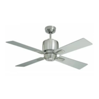
- Page 1 READ AND SAVE THESE INSTRUCTIONS VELOCE Ceiling Fan Owner's Manual Model Numbers CF230BS00 CF230ORB00 CF230WW00 17.0 Net Weight: Lbs. Part No. F40BP74340001 Form No. BP7434-1 U.L. Model No.: CF230...
-
Page 2: Safety Instructions
WARNING: To reduce the risk of fire or electrical shock, do not use this fan with any solid-state speed control device. WARNING: To avoid fire, shock or injury, do not use on Emerson or any other brand of control not specifically approved fro this fan. -
Page 3: Unpacking Instructions
2. Remove the fan assembly from the protective by Emerson Electric Co. could result in personal plastic bag. Place the fan assembly into the upper injury or property damage. foam pad with the lead wires up. -
Page 4: Electrical Requirements
Installation of Hanger Bracket IMPORTANT Your Emerson Ceiling is designed to be installed either in the standard manner, or in the close-to-the- ceiling manner. Using the standard method, the hanger ball/downrod assembly will suspend the fan several inches below the ceiling cover. Using the close-to-the-ceiling method, the ceiling cover installs directly on the fan motor housing, thus mounting the fan 3-1/2 inches closer to the ceiling than the standard methond. - Page 5 Installation of Hanger Bracket (continued) WARNING Turning off wall switch is not sufficient. To avoid possible electrical shock, be sure electricity is turned off at the main fuse box before wiring. All wiring must be in accordance with National and Local codes and the ceiling fan must be properly OUTLET BOX grounded as a precaution against possible electrical...
- Page 6 Installation of Blades & Light Assembly 1. Mount the blade flanges to the fan blades using 10-24 x 5/16" FLANGE three #10-24 x 5/16” Phillips blade screws per HEAD BLADE SCREW blade (supplied) (Figure 4). Repeat for the three (3 Per Blade) remaining blades.
-
Page 7: How To Assemble Your Ceiling Fan
Installation of Blades & Light Assembly (continued) 5. Position the light kit plate assembly onto the fan REINSTALL FAN motor assembly, careful to not pinch any wires MOTOR SCREW during installation. 6. Rotate the light kit plate assembly counter- clockwise to engage the two key slots with the two screws in the fan motor assembly. - Page 8 How to Assemble Your Ceiling Fan (Standard) (cont.) 4. Make sure the grommet is properly installed in the coupling cover then slide the coupler cover on DOWNROD the downrod until it rests on the motor housing (Figure 12). CEILING COVER TRIM RING 5.
-
Page 9: How To Wire Your Ceiling Fan
How to Wire Your Ceiling Fan (Standard) If you feel that you do not have enough electrical NOTE: Make all wiring connections using wire wiring knowledge or experience, have your fan connectors (supplied). Make sure that all installed by a licensed electrician. connections are tight, including ground, and that no bare wire is visible at the wire 1. - Page 10 How to Wire Your Ceiling Fan (Standard) (cont.) SUPPLY WHITE WIRE RECEIVER WHITE (NEUTRAL) WIRE RECEIVER BLACK WIRE SUPPLY BLACK WIRE (HOT) RECEIVER BLACK WIRE GROUND WIRE RECEIVER BLUE WIRE GREEN GROUND WIRE FROM HANGER BALL ANTENNA BLACK WIRE GREEN GROUND WIRE FROM FAN BLUE WIRE HANGER...
-
Page 11: Installation Of Ceiling Cover
Installation of Ceiling Cover (Standard) 1. Lift the ceiling cover up to the threaded studs and turn until the studs protrude through the holes in the ceiling cover (Figure 18). WARNING To avoid possible fire or shock, make sure that the electrical wires are completely inside the outlet box and not pinched between the ceiling cover and the ceiling. - Page 12 Close-to-the-Ceiling Installation (cont.) 6. Carefully lift the fan assembly up to the hanger CEILING COVER bracket. Pass the hook on the hanger bracket (Figure 22) through one of the screw holes (not the slots) in the ceiling cover (Figure 22). The hook HOOK must pass from the inside of the ceiling cover to the outside.
- Page 13 How to Wire Your Ceiling Fan (Close-to-the-Ceiling) (cont.) SUPPLY WHITE WIRE RECEIVER WHITE (NEUTRAL) WIRE RECEIVER BLACK WIRE SUPPLY BLACK WIRE (HOT) RECEIVER BLACK WIRE GROUND WIRE RECEIVER BLUE WIRE GREEN GROUND WIRE FROM HANGER BALL ANTENNA BLACK WIRE GREEN GROUND WIRE FROM FAN BLUE WIRE HANGER...
-
Page 14: Remote Control Procedures
General Preset Memory Feature Your Emerson Ceiling Fan/Light Remote Control Your Emerson receiver is equipped with a preset consists of hand-held transmitter and a receiver which memory feature. If the AC supply to the receiver is is mounted under the fan ceiling cover. The remote... - Page 15 Remote Control Procedures (cont.) Installation of Battery 1. Remove the battery cover by pressing firmly below the arrow and sliding the cover off the control REMOTE CONTROL LEVERS (Figure 27). 2. Install two AAA alkaline batteries and reinstall the battery cover. TWO AAA BATTERIES CODE...
-
Page 16: Energy Efficient Use Of Ceiling Fans
8 - 9 feet above the floor for optimal into the occupied space. Remember to adjust your airflow. Consult your Emerson Retailer for optional thermostat when using your ceiling fan - additional mounting accessories. energy and dollar savings could be realized with this simple step! Turn Off When Not in the Room. -
Page 17: Troubleshooting
Trouble Shooting WARNING: For your own safety, turn off power at fuse box or circuit breaker before trouble shooting your fan. TROUBLE PROBABLE CAUSE SUGGESTED REMEDY 1. Fan will not start. 1. Fuse or circuit breaker blown. 1.Check main and branch circuit fuses or circuit breakers. -
Page 18: Maintenance
The use of any other control not specifically accessories not designated for use with this product approved for this fan could result in fire, shock and by Emerson Electric Co. could result in personal personal injury. injury or property damage. - Page 19 Repair Parts Listing Model Numbers Description CF230BS00 CF230ORB00 CF230WW00 Hanger Pack, Consisting of: 762231-4 762231-8 762231-1 Hanger Bracket (1) — — — Hanger Ball (1) — — — Downrod 4.5” (1) — — — Parts Bag Containing: 764149 764149-1 764149 12 ga.
- Page 20 You will be responsible for all insurance, freight or other transportation charges to our factory or authorized service center. Your Emerson Air Comfort Ceiling Fan should be properly packed to avoid damage in transit since we will not be responsible for any such damage.
Need help?
Do you have a question about the VELOCE CF230ORB00 and is the answer not in the manual?
Questions and answers