Sign In
Upload
Download
Table of Contents
Contents
Add to my manuals
Delete from my manuals
Share
URL of this page:
HTML Link:
Bookmark this page
Add
Manual will be automatically added to "My Manuals"
Print this page
×
Bookmark added
×
Added to my manuals
Manuals
Brands
Konica Minolta Manuals
Measuring Instruments
CHROMA METER
Instruction manual
Konica Minolta CHROMA METER Instruction Manual
Hide thumbs
1
2
3
4
5
6
7
Table Of Contents
8
9
10
11
12
13
14
15
16
17
18
19
20
21
22
23
24
25
26
27
28
29
30
31
32
33
34
35
36
37
38
39
40
41
42
43
44
45
46
47
48
49
50
51
52
53
54
55
56
57
58
59
60
61
62
63
64
65
66
67
68
69
70
71
72
73
74
75
76
77
78
79
80
81
82
83
84
85
86
87
88
89
90
91
92
93
94
95
96
97
98
99
100
101
102
103
104
105
106
107
108
109
110
111
112
113
114
page
of
114
Go
/
114
Contents
Table of Contents
Bookmarks
Table of Contents
Safety Precautions
Introduction
Notes on Use
Operating Environment
Handling the Instrument
Backup Battery
Objective Lens and Close-Up Lens (Optional Accessory)
Recommended Battery Type
Notes on Storage
Instrument
Objective Lens
Notes on Cleaning
Notes on Transportation
Maintenance and Inspection
Disposal Method
Table of Contents
Standard Accessories
Optional Accessories
System Configuration Diagram
Names and Functions of Parts
Part Names
Major Functions of Parts
Key Panel
Major Functions of Keys
Viewfinder Display
Cs/Ls-150
Cs/Ls-160
Visibility Adjustment
LCD Screen
Layout
Measurement Screen
Various Messages
First Startup
Daily Operation
Error
Preparation
Installing Batteries
Notes on Use
Battery Level Indicator
Installing Batteries
Connecting the AC Adapter
Connection Procedure
Turning Power on ( | )/OFF ()
Setting the Power Switch to on
Setting the Power Switch to off
Wrist Strap
Attaching the Wrist Strap
Holding the Instrument
Caution During Carrying
Mounting
Settings
Selecting the Integration Time
Setting the Synchronized Measurement Mode
Selecting the Maximum/Minimum Value
Setting the Selectable Color Spaces
Selecting the Color Space
Selecting the Decimal Places for the Chromaticity Display
Selecting the Color Correction Factor (C.C.F.)
Selecting the Close-Up Lens
Selecting the Measuring Button Function
Setting the Measurement Result Saving
Setting the Display Brightness
Turning the Backlight ON/OFF
Setting the Auto Power off
Setting the Periodic Calibration Alert Display
Setting a Luminance Unit
Initializing the Settings
Setting the Internal Clock
Selecting the Display Language
Checking the Instrument Information
Measurement Preparation
Calibration
Calibration Channels
User Calibration
Performing User Calibration
By Measurement
By Selecting Stored Data
Calibration Value Input Rule
Setting/Changing the Target
Target
By Measurement and Registration
By Selecting Stored Data
By Entering Values
Measurement
Selecting and Checking the Target/Calibration Channel
Measurement
Selecting the Absolute Value/Difference/Ratio Display
Checking the Measurement Result
Deleting Stored Data
Deleting All Stored Data
Communication
Connection to a PC
Remote Mode
Explanation and Information
Light-Receiving Element (Sensor)
L V T Cp Duv Color Space
Dominant Wavelength/Excitation Purity
Object Color Measurement
Dimensions
Error Messages
Checking for Malfunction
Specifications
Memo
Advertisement
Quick Links
1
Connection to a Pc
Download this manual
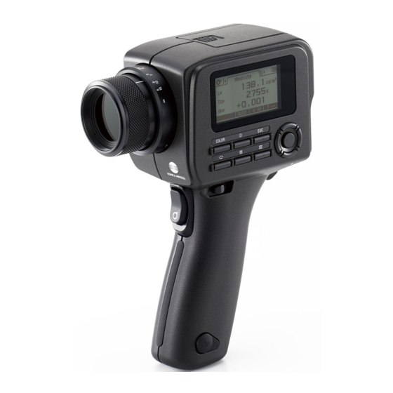
CHROMA METER
CS-150 / CS-160
LUMINANCE METER
LS-150 / LS-160
Instruction Manual
Please read this manual
before using the instrument.
Table of
Contents
Previous
Page
Next
Page
1
2
3
4
5
Advertisement
Table of Contents
Need help?
Do you have a question about the CHROMA METER and is the answer not in the manual?
Ask a question
Questions and answers
Related Manuals for Konica Minolta CHROMA METER
Measuring Instruments Konica Minolta CS-150 Setup Manual
(6 pages)
Measuring Instruments Konica Minolta CS-150 Manual
Chroma meter (3 pages)
Measuring Instruments Konica Minolta CS-2000 Instruction Manual
Spectroradiometer (92 pages)
Measuring Instruments Konica Minolta CS-200 Brochure
Chroma meter (6 pages)
Measuring Instruments Konica Minolta CA-310 Instruction Manual
Display color analyzer (122 pages)
Measuring Instruments Konica Minolta CM-700d Instruction Manual
(124 pages)
Measuring Instruments Konica Minolta CS-7 Operation Manual
Direct digitizer (424 pages)
Measuring Instruments Konica Minolta CM-25cG Instruction Manual
(130 pages)
Measuring Instruments Konica Minolta CA-410 Instruction Manual
Display color analyzer, probe + data processor (140 pages)
Measuring Instruments Konica Minolta CA-527 Series Instruction Manual
Display color analyzer (79 pages)
Measuring Instruments Konica Minolta CA-410 Instruction Manual
Display color analyzer, probe+ data processor (128 pages)
Measuring Instruments Konica Minolta CR-400 Instruction Manual
Chroma meter (160 pages)
Measuring Instruments Konica Minolta CM-M6 Instruction Manual
(128 pages)
Measuring Instruments Konica Minolta CM-36dGV Instruction Manual
(44 pages)
Measuring Instruments Konica Minolta CL-200A Instruction Manual
Chroma meter (60 pages)
Measuring Instruments Konica Minolta CA-2500 Series Instruction Manual
2d color analyzer (35 pages)
This manual is also suitable for:
Luminance meter
Cs-150
Cs-160
Ls-150
Ls-160
Table of Contents
Save PDF
Print
Rename the bookmark
Delete bookmark?
Delete from my manuals?
Login
Sign In
OR
Sign in with Facebook
Sign in with Google
Upload manual
Upload from disk
Upload from URL


Need help?
Do you have a question about the CHROMA METER and is the answer not in the manual?
Questions and answers