Table of Contents
Advertisement
Quick Links
Advertisement
Table of Contents

Related Manuals for VIVA FITNESS T2525


Summary of Contents for VIVA FITNESS T2525
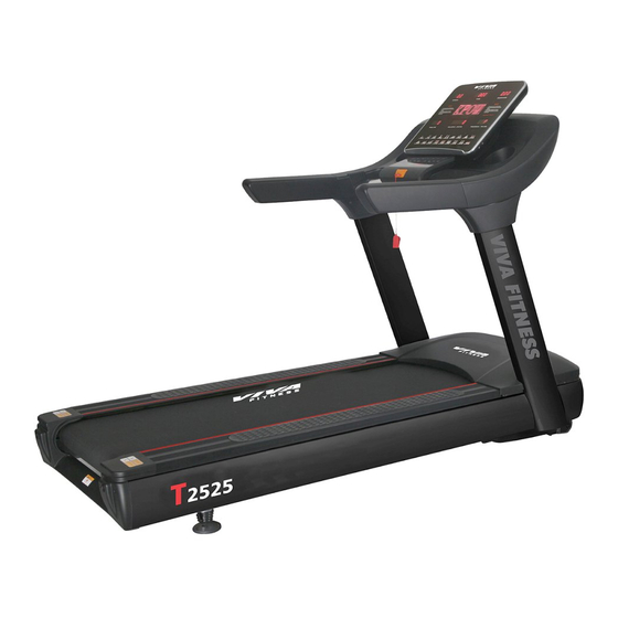
- Page 1 VIVA FITNESS MOTORIZED TREADMILL OWNER’S MANUAL ITEM NO. T2525...
- Page 2 WARNING Read all instructions carefully before using this product. Retain this owner’s manual for future reference: ----When using this treadmill, keep attaching the safety pull pin rope to your clothes. ----When you are running, keep your hand swinging natural, stare frontward, never look adown at your feet.
- Page 3 IMPORTANT SAFETY PRECAUSTION 1. Plug the power cord of the treadmill directly into a dedicated grounded circuit. This product must be grounded. If it has breakdown, grounding provides a path of least resistance for electric current to reduce the risk of electric shock. 2.
- Page 4 please have these replaced immediately by a qualified electrician – do not attempt to change or repair these yourself. 17. If the supply cord is damaged, it must be replaced by the manufacturer, its service agent or similarly qualified persons in order to avoid a hazard. 18.
-
Page 5: Assembly Steps
ASSEMBLY STEPS STEP 1: 1). Connect the Controller wire (93) with the Lower extension wire (92) properly; 2). Attach the Upright tube (2L/R)) onto the Main frame (1) with the Allen bolts (55) and Serrated washers (69) as shown. NOTE: Thread in all the Allen Bolts (55) Without Tightening. - 4 -... - Page 6 STEP 2: Connect the Upper extension wire (91) with the Lower extension wire (92) properly; Attach the Computer frame (3) onto the Upright tube (2L/R) with the Allen bolts (55) and Serrated washers (69) as shown; Tighten all the Allen bolts (55) installed via STEP 1. - 5 -...
- Page 7 STEP 3: 1. Connect the Computer connecting wire (90) with Upper extension wire (91) properly; Connect the Upper wire (107) with Lower wire (108) for Loudspeaker; Connect the Connecting wires (89) with Control wires (100) for Heart Rate; Connect the Connect wire (8) with Control wire (56) for Keyboard; Connect the Connect wire (44) and Control wire (45) for Safety Key.
- Page 8 STEP 4: Insert the A pin of the Upright tube cover (30a/b & 31a/b) to the B socket on the Computer frame (3) as shown, then fit the Upright tube cover (30a/b & 31a/b) onto the Upright tubes (2L/R), and secured with the Phillips tapping screws (83).
- Page 9 STEP 5: 1). Fill the equipped Silicon Oil into the Lubrication pump (112), then tight the Sealed cap as FIG.-C; If Treadmill comes w/o Auto Lubrication System, please ignore. 2). Fit the Motor cover (36) onto the Main frame (1) and secured with the Phillips tapping screws w/Washer (82) as shown.
-
Page 10: Grounding Methods
GROUNDING METHODS This product must be grounded. If it should malfunction or breakdown, grounding provides a path of least resistance for electric current to reduce the risk of electric shock. This product is equipped with a cord having an equipment-grounding conductor and a grounding plug. -
Page 11: Technical Parameter
an outlet having the same configuration as the plug. No adapter should be used with this product. TECHNICAL PARAMETER ASSEMBLY SIZE 2285×1025×1635 AS ORDER POWER(HP) (mm) FOLDING SIZE MAX OUTPUT AS ORDER (mm) POWER RUNNING SURFACE 580 × 1660 AS ORDER INPUT CURRENT (mm) apprx. - Page 12 SPEED: display Speed value; Display Range: 1.0 - 22.0KM/H. TIME: display Time; Display Range: 00:00 - 99:59. DIST.: display Distance; Display Range: 0.0 - 99.9. INCL.: display Incline; Display Range: 0 - 15. CAL./ STEPS: display Calories & current running Steps; Cal. Range: 0-999.9.
- Page 13 12%. ① “START” for startup, press START the treadmill will run at minimum speed 1.0KM/H; “STOP” for stop, the treadmill will stop via the key been pressed. ② “PROG.”: In standby state, you can select the programs from Manual Mode to “P1-P18, U1-U3, FAT” by pressing this key; Manual mode is set as default, and initial speed is 1.0 km/h, max speed up to 22km/h.
- Page 14 Below is the Profile chart for 18 Preset Programs in Metric System: Set time/16 = running time for each Section Time Sect. Program SPEED INCLINE SPEED INCLINE SPEED INCLINE SPEED INCLINE SPEED INCLINE SPEED INCLINE SPEED INCLINE SPEED INCLINE SPEED INCLINE SPEED INCLINE...
- Page 15 Set time/16 = running time for each Section Time Sect. Program SPEED INCLINE SPEED INCLINE SPEED INCLINE SPEED INCLINE SPEED INCLINE SPEED INCLINE SPEED INCLINE SPEED INCLINE SPEED INCLINE SPEED INCLINE SPEED INCLINE SPEED INCLINE SPEED INCLINE SPEED INCLINE SPEED INCLINE SPEED INCLINE...
- Page 16 programs to support customized setting based on the user’s specific situation: U01, U02 and U03. Setting the Customized Program: In standby state, continuously press “PROG.” to the required Customized program (U01~ U03); at the same time, the “TIME” window flashing, display the preset time, press “INCLINE+”/ “INCLINE-”...
- Page 17 1) Remove Safety Key, press SPEED+ and SPEED- for 1s at the same time, the total mileage Km will display in the Speed and Incline window: the first 3 higher digits displayed in SPEED window, and the lower 3 digits displayed in the Incline window.
-
Page 18: Troubleshooting
Code Description Fault Reason Trouble Shooting Digital meter and inverter Communication Check the connection and fits it error between not connected well Digital meter and Digital meter broken Change digital meter Inverter Inverter broken Change inverter Temp Sensor short circuit Over- Heat Controller chip 358/324 Change inverter... -
Page 19: Maintenance Instructions
1. The Warm Up Phase This stage helps get the blood flowing around the body and the muscles working properly. It will also reduce the risk of cramp and muscle injury. It is advisable to do a few stretching exercises as shown below. - Page 20 RUNNING BELT CENTERING AND TENSION ADJUSTMENT DO NOT OVERTIGHTEN the Running Belt. This may cause reduced motor performance and excessive roller wear. TO CENTER RUNNING BELT ● Place treadmill on a level surface ● Run treadmill at approximately 3.5 mph ●...
- Page 21 BEFORE CLEANING OR SERVICING THE UNIT. CLEANING General cleaning or the unit will greatly prolong the treadmill. Keep treadmill clean by dusting regularly. Be sure to clean the exposed part of the deck on either side of the walking belt and also the side rails.
-
Page 22: Exploded Drawing
EXPLODED DRAWING - 21 -... -
Page 23: Parts List
PARTS LIST Part Part Description Description Allen Cylindrical head bolt M10*115 Main frame 2L/R Allen Cylindrical head bolt Upright tube M10*65 Allen Cylindrical head bolt M10*55 Computer frame Allen Cylindrical head bolt Incline frame M6*15 Allen Cylindrical head bolt Idle wheel rack M6*40 Running deck retainer Nylon nut M10... - Page 24 Motor cover Controller wire Front frame cover Amplifier board Rear roller end cap Loudspeaker Deck stopper USB socket Silicon gel cushion MP3/Headphone jack Running belt AC motor Running deck Incline motor Belt Heart rate control wire Safety key connect wire Power cable Safety key control wire Power switch...
Need help?
Do you have a question about the T2525 and is the answer not in the manual?
Questions and answers