
Subscribe to Our Youtube Channel
Related Manuals for Fischer Panda AGT 45-VS PMS


Summary of Contents for Fischer Panda AGT 45-VS PMS
-
Page 1: Panda 45-Vs Pms Manual
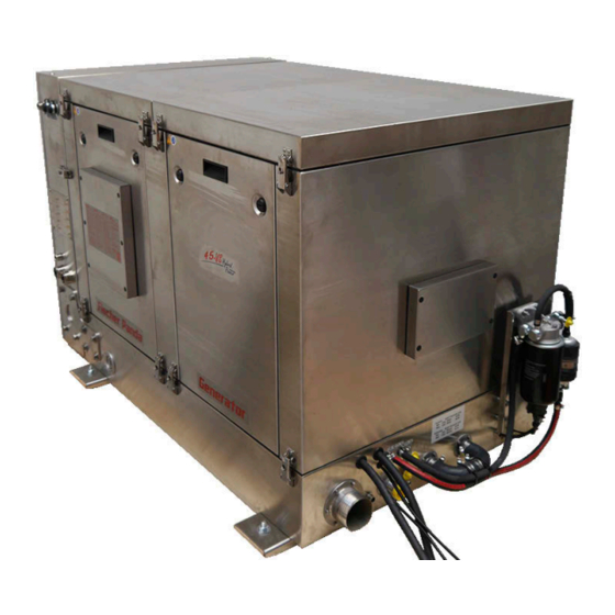
Panda 45-VS PMS manual Super silent technology 300-500 V / 150 A / 0-45 kW Fischer Panda part number: 0032821 P200089_Panda_45-VS_PMS_s03370_Buch_eng.R02 3.3.22... -
Page 2: Current Revision Status
Reproduction and modification of the manual is permitted only after by agreement and with the permission of the manufacturer! Fischer Panda GmbH, 33104 Paderborn, reserves all rights regarding text and graphics in this document. Details are given to the best of our knowledge. No liability is accepted for correctness. Please note: technical modifications aimed at improving the product may be implemented without prior notice. -
Page 3: Table Of Contents
Opening the Fischer Panda Transport Box ..................24 4.3.1 Bolted Fischer Panda Transport Box .................. 24 4.3.2 Fischer Panda Transport Box with metal tab closure ............24 Transport and Loading........................24 4.4.1 Transporting the generator ....................24 4.4.2... - Page 4 Table of Contents 4.5.1 Variable speed generators ....................25 Opening the MPL sound insulation capsule..................27 Special servicing instructions and measures for extended downtime and decommissioning ..... 29 4.7.1 Instructions regarding the starter battery during extended downtime ......... 29 4.7.2 Measures for short-term downtimes ................
- Page 5 Protection conductor ......................87 9.2.5 Operational monitoring system on the Fischer Panda Generator ........87 Checks before starting - see the Remote Control Panel data sheet........... 87 Starting the generator - see Remote Control Panel data sheet............87 Switching off the generator - see separate Remote Control Panel data sheet.......
- Page 6 Table of Contents 10.4 Starting problems ..........................92 10.4.1 Clogged fuel filter ........................ 92 10.4.2 Troubleshooting table ......................92 10.5 Faults on the Hatz engine ........................93 10.5.1 Hatz ECU fault code table ....................93 11 Maintenance Instructions ........................
- Page 7 Table of Contents 12.5 Dimensions ............................142 Current revision status........................... 144 13.1 Download ............................145 14 Panda fpControl Safety Instructions......................147 14.1 Personnel............................147 14.2 Safety instructions ..........................147 14.3 Function description.......................... 148 14.4 Proper use ............................
- Page 8 Table of Contents 15.5.2.5 Setting the display mode of the CP-G overview page ........173 15.5.2.6 Setting the language of the text pages of the CP-G ......... .. 173 15.5.2.7 Setting the Temperature Unit ................174 15.5.2.8 Setting the Aural Alarm ..................174 15.5.2.9 Setting the display to flash in the event of a fault ..........
- Page 9 Your generator offers you the possibility of generating your own power - wherever you are - making you all the more independent. Not only do you have a Fischer Panda generator on board; you are also supported worldwide by our Fischer Panda team. Please take the time to read this information. We can also assist you with: Inspecting the generator installation and guarantee Every generator has a world-wide guarantee.
-
Page 10: General Instructions And Regulations
General instructions and regulations 1. General instructions and regulations 1.1 The cardinal rule is safety! Warning symbols are used throughout this manual to warn of the risk of personal injury or lethal danger when certain maintenance tasks or operating procedures are performed. Instructions marked in this way must always be read and followed carefully. -
Page 11: Disposal
General instructions and regulations electrical connections of the generator. Generator and coolant may be hot during and after use. Warning! Hot surface/material Risk of being burnt/scalded! Excess pressure may develop in the cooling system when operating. Batteries contain corrosive acids and alkalis. Warning! Improper handling can cause the batteries to heat up and burst. -
Page 12: Customer Registration And Warranty
• You will receive free upgrades, when necessary. Further advantages: By providing full details, the Fischer Panda technicians will be able to offer rapid assistance, as 90% of break-downs are caused by peripheral faults. Problems due to installation errors can be recognised in advance. -
Page 13: Safety Instructions - Safety First
General instructions and regulations 1.4 Safety Instructions - safety first! 1.4.1 Safe operation Careful handling of the equipment is the best insurance against an accident. Read the handbook diligently, and make sure you understand it before starting up the equipment. All operators, regardless of their experience level, shall read this handbook and additional pertinent manuals before commissioning the equipment or installing an attachment. -
Page 14: Safe Handling Of Fuels And Lubricants
General instructions and regulations 1.4.5 Safe handling of fuels and lubricants Keep fuels and lubricants away from naked fire. Before filling up the tank and/or applying lubricant, always shut down the generator and secure it against accidental start-up. Do not smoke and avoid naked flame and sparking near fuels and the generator. Fuel is highly flammable and may explode under certain conditions. -
Page 15: Safety Precautions Against Burns And Battery Explosions
General instructions and regulations 1.4.7 Safety precautions against burns and battery explosions The generator and its cooling agents and lubricants as well as the fuel can get hot while the generator is operated. Handle hot components with care such as exhaust components, radiators, hoses and the engine block both during operation and after the generator has been switched off. -
Page 16: Warning And Instruction Signs
General instructions and regulations Use only suitable tooling and appliances and familiarise yourself with their functions to prevent secondary damage and/or injury. Always keep a fire extinguishing unit and a first aid box handy while performing maintenance work. 1.5 Warning and instruction signs Keep warning and instruction signs clean and legible. -
Page 17: Switch Off All Loads When Working On The Generator
General instructions and regulations 1.5.1.2 Switch off all loads when working on the generator All loads must be disconnected prior to working on the generator to avoid damage to the devices. 1.5.1.3 Potential equalisation in Panda AGT-DC and VS generators For further information specific to your generator, see the section on installation. - Page 18 General instructions and regulations components regularly for chafing and insulation defects. ATTENTION! For battery charger generators (Fischer Panda AGT-DC and VS)! Prior to installation, verify that the voltage of the battery bank complies with the output voltage of the generator.
-
Page 19: In Case Of Emergency First Aid
In case of Emergency First Aid 2. In case of Emergency First Aid First Aid in case of accidents by electrical shocks 5 Safety steps to follow if someone is the victim of electrical shock Do not touch the injured person while the generator is running. Switch off the generator immediately. -
Page 20: When An Adult Stops Breathing
In case of Emergency First Aid 2.1 WHEN AN ADULT STOPS BREATHING DO NOT attempt to perform the rescue breathing Warning: techniques provided on this page, unless certified. Performance of these techniques by uncertified personnel could result in further injury or death to the victim. -
Page 21: Special Instructions And Hazards In The Case Of Vs-Dc Generators
5 safety rules). The hybrid charger may only be operated in conjunction with Fischer Panda generators as the system is designed for each generator. It is not permitted to connect it to other generators or a three-phase network and this may lead to malfunction, destruction of the device, fire or a life-threatening shock. -
Page 22: Fire Protection Measures
Special instructions and hazards in the case of VS-DC generators the appropriate cross-section of the connecting cable must be supplied by the customer There is a fire risk if this is not the case. 3.1.2 Fire protection measures All components in the vicinity of live parts shall be protected against fire. All connection interfaces on live parts shall be regularly inspected for heat development (infra-red thermometer). -
Page 23: Basics
This manual serves as the work and operating instructions for the user and operator of Fischer Panda generators. The handbook serves as a foundation and guide for the installation and servicing of Fischer Panda generators in a manner that complies with legislation and regulation. It does not replace professional judgement and design, nor the modification of the installation to comply with local conditions and national/international regulations. -
Page 24: Operators
4.4.1 Transporting the generator • The generator may only be transported in an upright position. • The Fischer Panda transport box must be used when transporting the generator. The generator shall be securely attached to the bottom of the box. -
Page 25: Fischer Panda Generator Scope Of Delivery
Fig. 4.4.2-1: Example of lifting yoke Illustrative example 4.5 Fischer Panda Generator scope of delivery The scope of delivery of the Fischer Panda generators includes the following parts: 4.5.1 Variable speed generators Fischer Panda VS generator Fig. 4.5-1: Fischer Panda Generator... - Page 26 Illustrative example Fischer Panda manual Fig. 4.5-4: Handbook The Fischer Panda manual comprises the following com- ponents: • Clear plastic folder with general information, guarantee conditions, installation protocol (installation report) and service list.
-
Page 27: Opening The Mpl Sound Insulation Capsule
Basics 4.6 Opening the MPL sound insulation capsule Tools needed: Set of screwdrivers 1. To open the sound insulation capsule, the closures must Fig. 4.6-1: Sound insulation capsule - side cover be rotated anti-clockwise through approximately 180°. 2. Use a flat-bladed screwdriver for this purpose. Pull the side-walls out using the recessed grips. - Page 28 Basics 4. Closure open Fig. 4.6-3: Closure open 5. Open all capsule closures. Fig. 4.6-4: Capsule lid 6. Remove the capsule lid. 7. Close the capsule in the reverse order. Page 28 - Chapter 4: Basics 3.3.22...
-
Page 29: Special Servicing Instructions And Measures For Extended Downtime And Decommissioning
The measures mentioned here are "standard" measures for downtime/decommissioning as well as recommissioning. As the precise circumstances of the downtime and decommissioning are not known to Fischer Panda, these directions can serve as a template and example. The measures must be adapted in accordance with the local circumstances and regulations by a qualified specialist. -
Page 30: Measures For Short-Term Downtimes
Basics Fischer Panda recommends: Note: • Install a battery disconnect switch and switch it to the “Off” position at the machine. (Cutting the battery circuit.) • The positive pole of the battery must be secured close to the battery. • Regularly check contacts for corrosion. -
Page 31: Measures For Removing Surface Protection After Medium-Term Downtimes (3 To 6 Months)
Basics • Clean the raw water filter. • Remove the impeller (if present) and store. Before recommissioning, remove preservatives and pro- Attention! tective measures! 4.7.3.2 Measures for removing surface protection after medium-term downtimes (3 to 6 months) • Check battery charge status and recharge if necessary. Observe instructions of the battery manufacturer. •... -
Page 32: Measures For Removing Preservatives After Long-Term Downtime / Recommissioning (More Than 6 Months)
Basics Cover generator apertures Attention! Cleaning fluids and preservatives must not enter the alternator. Risk of destroying the alternator. • Clean engine as per manufacturer's instructions. • Spray engine parts and V-belt pulleys with preservative. • Clean air filter housing and spray with preservative. •... - Page 33 Basics Fischer Panda recommends: Note: After long-term downtime, a complete inspection must be performed in accordance with the engine manufacturer. 3.3.22 Chapter 4: Basics - Page 33...
- Page 34 Basics Intentionally left blank Page 34 - Chapter 4: Basics 3.3.22...
-
Page 35: Ec Declaration Of Conformity
0032821 Year of manufacture 2021- Function description20 The Fischer Panda diesel generator is intended solely for use as a permanently-installed power generator in (vehicles,trailers and mobile containers) (inland waterway vessels) (seagoing vessels). We hereby declare that this machine, on the basis of its design and construction and in the version that we... - Page 36 Electromagnetic Compatibility (EMC) - Testing and measurement techniques - Immunity test in respect of conducted interference induced by high-frequency fields 04/0847:2014-08 The person authorized to compile the Sören Hupe technical file Fischer Panda GmbH Otto-Hahn-Straße 40 33104 Paderborn Paderborn, _____22.09.2021________________ Place, date Dipl.-Ing. Stephan Backes (Managing Director) Paderborn, _____22.09.2021________________...
-
Page 37: Ukca Declaration Of Conformity
0032821 Year of manufacture 2021- Function description The Fischer Panda diesel generator is intended solely for use as a permanently-installed power generator in (vehicles, trailers and mobile containers) (inland waterway vessels) (seagoing vessels). We hereby declare that this machine, on the basis of its design and construction and in the version that we... - Page 38 Electromagnetic Compatibility (EMC) - Testing and measurement techniques - Immunity test in respect of conducted interference induced by high-frequency fields 04/0847:2014-08 The person authorized to compile the Sören Hupe technical file Fischer Panda GmbH Otto-Hahn-Straße 40 33104 Paderborn Paderborn, _____22.09.2021________________ Place, date Dipl.-Ing. Stephan Backes (Managing Director) Paderborn, _____22.09.2021________________...
-
Page 39: The Panda Generator
The Panda Generator 7. The Panda Generator 7.1 Position of the identification plate Fig. 7.1-1: Identification plate on the generator Fig. 7.1-2: Description of the identification plate 3.3.22 Chapter 7: The Panda Generator - Page 39... -
Page 40: Description Of The Generator
The Panda Generator 7.2 Description of the generator 7.2.1 Right-hand side view Fig. 7.2.1-1: Right-hand side view 08 09 01. Connections, see Fig. 7.2.1-2, “Generator connections on right- 07. Fan grille - do not cover! hand side,” auf Seite 41 08. - Page 41 The Panda Generator Fig. 7.2.1-2: Generator connections on right-hand side 01. Feed-through for customer-supplied communication cable 04. Feed-through for earth connection 02. RJ45 CAN Bus plug - customer-supplied 05. Feed-through for the generator output (-) 03. RJ45 CAN Bus internal plug 06.
-
Page 42: Left-Hand Side View
The Panda Generator 7.2.2 Left-hand side view Fig. 7.2.2-1: Left-hand side view 01. Air filter housing 09. fpControl circuit board 02. Crankcase vent 10. Coolant pump 03. Intercooler 11. Oil filler neck 04. Fuel rail 12. Injection pump 05. Control cabinet 13. -
Page 43: Front View
The Panda Generator 7.2.3 Front view Fig. 7.2.3-1: Front view 01. Recessed grip 04. fpControl Panel 02. Control cabinet door 05. Recessed grip 03. Fastener for control cabinet door (8 pieces) 3.3.22 Chapter 7: The Panda Generator - Page 43... - Page 44 The Panda Generator Fig. 7.2.3-2: Open the control cabinet 01. Fan 07. Terminal strip 9X8 02. Hybrid charger 08. Transformer 9T6 03. Communication Interface 09. Relay 9K8 04. Terminal strip for fpControl Panel 10. Load output connection (+) 05. Terminal strip 9X5 11.
-
Page 45: Rear View
The Panda Generator 7.2.4 Rear view Fig. 7.2.4-1: Rear view 02 03 01. Air filter housing 05. Generator housing 02. DC relays and fuses 06. Fuel filter with water sensor 03. Hatz engine ECU 07. Fuel pump 04. Connections, see Fig. 7.2.4-2, “Generator connections - Rear view,”... - Page 46 The Panda Generator Fig. 7.2.4-2: Generator connections - Rear view 01. Exhaust outlet 07. Connection for the coolant expansion tank inlet 02. Starter battery 12 V 08. Connection for the coolant expansion tank outlet 03. Control system supply line (-) 09.
-
Page 47: Top View
The Panda Generator 7.2.5 Top view Fig. 7.2.5-1: Top view 05 06 01. Air filter housing 06. Fuel pump 02. Turbocharger 07. Coolant pump 03. Exhaust mixer under heat insulation 08. Oil filler neck 04. Control cabinet 09. Heat exchanger 05. -
Page 48: Function Groups And Functional Diagrams
The Panda Generator 7.2.6 Function groups and functional diagrams 7.2.7 fpControl Panel The remote control panel is equipped with various monitoring functions, which increase the functionality and operational safety of the generator. Various areas of the generator are monitored that trigger an alarm on the remote control panel and that can shut down the generator as soon as a fault is detected. -
Page 49: The Cooling System
The Panda Generator 7.2.8 The cooling system Fig. 7.2.8-1: The cooling system 3.3.22 Chapter 7: The Panda Generator - Page 49... -
Page 50: Fuel System
The Panda Generator 7.2.9 Fuel system Fig. 7.2.9-1: Fuel system Page 50 - Chapter 7: The Panda Generator 3.3.22... -
Page 51: Combustion Air System
The Panda Generator 7.2.10 Combustion air system Fig. 7.2.10-1: Combustion air system 3.3.22 Chapter 7: The Panda Generator - Page 51... -
Page 52: Electrical System
The Panda Generator 7.2.11 Electrical system Fig. 7.2.11-1: Electrical system Page 52 - Chapter 7: The Panda Generator 3.3.22... -
Page 53: Lubricant System
The Panda Generator 7.2.12 Lubricant system Fig. 7.2.12-1: Lubricant system 3.3.22 Chapter 7: The Panda Generator - Page 53... -
Page 54: Sensors And Switches For Operational Monitoring
The Panda Generator 7.2.13 Sensors and switches for operational monitoring Thermosensor on the exhaust mixer Fig. 7.2.13-1: Thermosensor on the exhaust mixer Thermo-switches and sensors on the winding Fig. 7.2.13-2: Thermo-switches and sensors on the winding Oil pressure sensor Fig. 7.2.13-3: Oil pressure sensor Other temperatures are displayed on the Hatz ECU Note! device. -
Page 55: Installation Instructions
Fischer Panda, these installation instructions can only serve as a template and example. The installation must be adapted in accordance with the local circumstances and regulations and performed by appropriate specialist. - Page 56 Installation Instructions Generator weight: approx. 595 kg! Attention! 4. Lift the generator by means of a crane. 5. After installing, unscrew the 4 lifting eyes and re-install the capsule components. Fig. 8.2-2: Hoisting procedure 01. Crane 03. Generator 02. Lifting gear (example only, not included in scope of supply) Page 56 - Chapter 8: Installation Instructions 3.3.22...
-
Page 57: Placement
• The generator may only be operated by authorised personnel. 8.3.2 Installation location and base Since Fischer Panda generators have extremely compact dimensions, they can be installed in cramped locations; they are therefore often installed in places that are difficult to access. Please consider that even almost... -
Page 58: Advice For Optimal Sound Insulation
Installation Instructions 8.3.3 Advice for optimal sound insulation The appropriate base consists of a sturdy framework, on Fig. 8.3.3-1: Generator base which the generator is fastened by means of vibration dampers. Since the power unit is "open" from below, the combustion air can be sucked in unhindered. -
Page 59: Generator Connections
Installation Instructions 8.4 Generator connections All electrical supply cables within the capsule must be securely connected to the engine and the generator. This is also applies to fuel lines and cooling water supply lines. Attention! Lethal danger - High voltage It is imperative that the electrical connections are laid out and implemented according to the applicable regulations. - Page 60 Installation Instructions Fig. 8.4-2: Generator connections 01. Feed-through for customer-supplied communication cable 04. Feed-through for earth connection 02. RJ45 CAN Bus plug - customer-supplied 05. Feed-through for the generator output (-) 03. RJ45 CAN Bus internal plug 06. Feed-through for the generator output (+) Page 60 - Chapter 8: Installation Instructions 3.3.22...
-
Page 61: Connecting The Cooling System - Raw Water
Installation Instructions 8.5 Connecting the cooling system - raw water 8.5.1 General instructions The generator should have its own feed line and should not be connected to the cooling systems of other engines. Ensure that the following installation instructions are complied with: 8.5.2 Arrangement of the through-hull fitting in yachts - schematic It is good practice for yachts to use a through-hull fitting with Fig. -
Page 62: Raw Water Installation Diagram
A repair is then very expensive. A spare impeller and a spare pump should always be on board. The old pump can be sent back to Fischer Panda for a cost-effective general overhaul. -
Page 63: Installing The Generator Below The Waterline
Installation Instructions 8.5.5 Installing the generator below the waterline If the generator cannot be fitted at least 600 mm above Fig. 8.5.5-1: Air-bleed valve the waterline, it is essential that a vent valve is installed in the raw water line. Possible heeling must be taken into consideration if installed to the side of the "mid-ship line"! The water hose for the external vent valve at the rear of the capsule is separated at... -
Page 64: Raw Water Installation Diagram
Installation Instructions 8.5.5.1 Raw water installation diagram Fig. 8.5.5.1-1: Example of the raw water installation diagram Page 64 - Chapter 8: Installation Instructions 3.3.22... -
Page 65: Installation Of The Standard Exhaust System - Diagram
The generator exhaust system must be led through the side of the vessel to the outside completely separately from the exhaust system of the main engine or other units. A special water lock is offered in the Fischer Panda accessory list, which also offers highly efficient noise attenuation. -
Page 66: Potential Causes For Water In The Exhaust Line
Installation Instructions has free access to the combustion chamber. The raw water then flows by capillary attraction past the pistons and into the engine oil. If it has been ascertained that the engine oil level is unusually high and/or the oil has a grey colour, the engine may no longer be used. -
Page 67: The Volume Of The Exhaust Water Lock
Installation Instructions 8.7.3 The volume of the exhaust water lock The exhaust water lock must be of such dimensions that it can contain the total volume of water flowing back from the exhaust line. The volume of water depends on the length (L) and the diameter of the exhaust line. While the diesel engine is running, cooling water is continuously sprayed into the exhaust system and then forced out by the back pressure of the exhaust gases. - Page 68 Installation Instructions Ideal position of the water lock Fig. 8.7.3.1-1: Ideal position of the water lock As depicted in Fig. 8.7.3.1-1 the water lock is mounted amidships below the generator. When heeling, the position of the water lock relative to the critical point on the exhaust line changes only minimally.
-
Page 69: Example For The Installation Of The Water Lock Outside Of The Mid-Line With Possible Con- Sequences
Installation Instructions Summary: It is imperative that the specified minimum height of 600 mm is maintained and this applies only if the water lock is installed in the ideal position amidships below the generator. A higher position is strongly recommended, if a heel of 45 degrees must be taken into account. - Page 70 Installation Instructions B) Installation distance of 1 000 mm between the exhaust water lock and the centre line of the generator: Installation distance of 1 000 mm between the exhaust Fig. 8.7.3.2-3: Water lock 1 000mm from the mid-line of the water lock and the centre line of the generator: generator 30 degree heel - Fig.
-
Page 71: Exhaust/Water Separator
For optimal reduction of the exhaust noise, the use of an additional silencer close to the through-hull fitting is recommended. Fischer Panda offers a component for this purpose that acts as both an "exhaust goose neck" and a water separator. This "exhaust/water separator" enables the cooling water to be led away via a separate line. This greatly reduces the exhaust noise on the outside of the yacht. - Page 72 Installation Instructions Fig. 8.8.1-1: Example of an unfavourable exhaust installation Example of an unfavourable installation: - Water lock not far enough below the level of the generator - Distance between the water lock and the goose neck too great Schematic diagram Page 72 - Chapter 8: Installation Instructions 3.3.22...
-
Page 73: Connecting The Cooling System - Raw Water
8.9.1 Position of the external cooling water expansion tank The Fischer Panda generator is usually supplied with a supplementary external cooling water expansion tank. This tank must be installed in such a way that its lower edge is at least 200 mm higher than the upper edge of the noise attenuation capsule. - Page 74 Installation Instructions Fig. 8.9.1-2: External cooling water expansion tank Page 74 - Chapter 8: Installation Instructions 3.3.22...
-
Page 75: Installing The Fuel System
Installation Instructions 8.10 Installing the fuel system Fig. 8.10-1: Fuel system - Schematic diagram 3.3.22 Chapter 8: Installation Instructions - Page 75... -
Page 76: Connecting The Fuel Line To The Tank
(e.g. day tank), then a non-return valve must be installed on the fuel return line to ensure that no fuel is fed into the injection pump via the return line. The Fischer Panda generator is equipped with a fuel pre- Note! filter and a fine fuel filter. -
Page 77: Installing The Generator Dc System
Installation Instructions 8.11 Installing the generator DC system 8.11.1 General safety instructions when dealing with batteries Take note of the instructions and installation guidelines Warning!: of the battery manufacturer. Only use batteries that are approved by the battery manufacturer for this application. These instructions shall apply in addition to the instructions of the battery manufacturer: •... -
Page 78: Connecting The Starter Battery
• The battery terminals must be protected against accidental short-circuiting. • Inside the Fischer Panda generator capsule, the positive battery cable must be routed so that it is protected from heat and vibrations by means of an adequate conduit/protective sleeve. It must be routed so that it does not touch parts that rotate or become hot during operation, such as belt pulleys, exhaust manifolds, exhaust pipes and the engine itself. - Page 79 Installation Instructions Fig. 8.11.3-1: 12 V starter battery connection - Schematic diagram 01. Generator 04. 425 A fuse 02. Main battery switch 05. Starter battery 12 V 03. 40 A fuse 3.3.22 Chapter 8: Installation Instructions - Page 79...
-
Page 80: Connecting The Remote Control Panel
Installation Instructions 8.11.4 Connecting the remote control panel The remote control panel must be connected as described in the data sheet of the remote control panel. 8.11.5 Electrical connections Before the electrical system is installed, take note of the ATTENTION! Lethal danger - High voltage safety instructions in the respective chapter. - Page 81 Installation Instructions Fig. 8.11.5-1: Electrical connections 01. Communication cable - customer-supplied 05. Generator output (+) 02. RJ45 CAN Bus - customer-supplied 07. Main battery switch 03. Internal RJ45 CAN Bus 08. 40 A fuse 04. PE conductor 09. 425 A fuse 05.
- Page 82 Installation Instructions Fig. 8.11.5-2: Customer supplied connection diagram Page 82 - Chapter 8: Installation Instructions 3.3.22...
- Page 83 Installation Instructions Fig. 8.11.5-3: Customer supplied connection diagram 3.3.22 Chapter 8: Installation Instructions - Page 83...
-
Page 84: Start-Up
The original start-up log of the generator must be sent to Note! Fischer Panda to obtain the full warranty. Make sure that you retain a copy for your records. Page 84 - Chapter 8: Installation Instructions... -
Page 85: Generator Operating Instructions
Generator Operating Instructions 9. Generator Operating Instructions 9.1 Personnel The generator may only be started up by authorised and instructed personnel. The operator shall read the manual in its entirety before starting up the equipment and shall familiarise themselves with the hazards and safety precautions. -
Page 86: General Instructions Regarding Operation
9.2.1.2 Tips regarding the starter battery Fischer Panda recommends the use of a commercially available starter batteries. The recommended starter battery capacity (Ah) should be doubled for use in extreme winter conditions. It is recommended that the starter battery be charged regularly (every 2 months). -
Page 87: Load Placed On The Engine In Continuous Use And Overloading
2--3 hours. The overall design of Fischer Panda Generator ensures that even when operated at full load under extreme condi- tions, overheating of the engine will not occur. It must, however, be taken into account that when the engine is oper- ated at full load, the exhaust emissions (soot formation) will deteriorate. -
Page 88: Switching Off The Generator - See Separate Remote Control Panel Data Sheet
Generator Operating Instructions 9.5 Switching off the generator - see separate Remote Control Panel data sheet The notes and instructions in the Remote Control data Note! sheet must be complied with. Ensure compliance with the general safety instructions at the beginning of this manual. -
Page 89: Generator Faults And Errors
Generator Faults and Errors 10. Generator Faults and Errors 10.1 Personnel The work described here can be performed by the operator unless highlighted differently. Further repair work may only be performed by specially trained technical personnel or by authorised workshops (Fis- cher Panda Service Points). - Page 90 Generator Faults and Errors Contact with engine oil, fuel and anti-freeze agents may Caution: Risk of poisoning result in harm to health when inhaled, swallowed or when coming into contact with skin. Therefore: • Avoid skin contact with engine oil, fuel and anti-freeze. •...
-
Page 91: Tools And Measuring Instruments
Generator Faults and Errors 10.2 Tools and measuring instruments In order for you to be able to deal with faults while travelling, the following tools and measuring instruments should belong to the equipment kept on board: • Multimeter for voltage (AC/DC), frequency and resistance •... -
Page 92: Generator Output Voltage Is Too Low
Generator Faults and Errors 10.3.1 Generator output voltage is too low Before working on the system, see “Safety Instructions - ATTENTION! safety first!” on page 13. If the generated AC voltage is too low, then the consumers should be disconnected, one after the other, in order to reduce the load on the generator. -
Page 93: Faults On The Hatz Engine
Generator Faults and Errors 10.5 Faults on the Hatz engine If the ECU of the Hatz engine detects a fault, it is displayed on the fpControl Panel. If an engine fault arises, the generator is stopped by the Fig. 10.5-1: Event-code fpControl. - Page 94 Generator Faults and Errors FaultCheckDescription Possible Causes The sensor raw signal CEngDsT_uRaw (voltage) is above wiring harness or component CEngDsT_SRC.uMax_C (4957mV). The sensed raw voltage value CEngDsT_uRaw is less than wiring harness or component CEngDsT_SRC.uMin_C (359mV). 22040 19 Timeout Error of CAN-Receive-Frame TSC1TE CAN transmitter 22058 19 Reported SPI and COM-Errors of a Cy146...
- Page 95 Generator Faults and Errors FaultCheckDescription Possible Causes SRC High for Environment Temperature wiring harness or component SRC low for Environment Temperature wiring harness or component In between of several camshaft revolutions there are too many tone wheel defective or too less camshaft edges present or the distance or the series of the camshaft edges is unplausible.
- Page 96 Generator Faults and Errors FaultCheckDescription Possible Causes 5324 Array of DFCs for failure in i+1th Glow Plug 5325 Array of DFCs for failure in i+1th Glow Plug 5326 Array of DFCs for failure in i+1th Glow Plug 5327 Array of DFCs for failure in i+1th Glow Plug 5324 Array of DFCs for short circuit in i+1th Glow Plug 5325...
- Page 97 Generator Faults and Errors FaultCheckDescription Possible Causes Diagnostic fault check for min error of COM message wiring harness or component 20220 2 Diagnostic fault check to report the NTP error in ADC monitoring ECU internal fault 20220 11 Diagnostic fault check to report the ADC test error ECU internal fault 20220 14 Diagnostic fault check to report the error in Voltage ratio in ADC...
- Page 98 Generator Faults and Errors FaultCheckDescription Possible Causes 20233 11 Diagnostic fault check to report the error due to torque ECU internal fault comparison 20234 11 Diagnosis of curr path limitation forced by ECU monitoring level ECU internal fault 20234 20 Diagnosis of lead path limitation forced by ECU monitoring level ECU internal fault 20234 21...
- Page 99 Generator Faults and Errors FaultCheckDescription Possible Causes 1244 short circuit to battery in the high side of the pressure control valve 1244 short circuit to ground in the high side of the pressure control valve 1244 short circuit to battery of pressure control valve output 1244 short circuit to ground of the pressure control valve output 1244...
- Page 100 Generator Faults and Errors FaultCheckDescription Possible Causes 23613 2 If the rail pressure RailP_pFlt exceeds the limiting value 1.) Metering unit is stuck in open position 2.) zero delivery Rail_MeUnMon.pFltMax_C (1.750.000 hPa) an error will be throttle clogged up 3.) metering unit without detected.
- Page 101 Generator Faults and Errors FaultCheckDescription Possible Causes No load error wiring harness or component Short circuit to battery error wiring harness or component Short circuit to ground error wiring harness or component 20251 11 Visibility of SoftwareResets in DSM ECU internal fault 20251 20 Visibility of SoftwareResets in DSM ECU internal fault...
- Page 102 Generator Faults and Errors Intentionally left blank Page 102 - Chapter 10: Generator Faults and Errors 3.3.22...
-
Page 103: Maintenance Instructions
The maintenance work described here can be performed by the operator unless otherwise labelled. Further maintenance work may only be performed by specially trained technical personnel or by authorised workshops (Fischer Panda Service Points). This applies in particular to valve adjustments, work on the diesel injection system, and to engine repairs. -
Page 104: Disposal Of Engine Fluids
Maintenance Instructions Contact with engine oil, fuel, and anti-freeze agents can Caution! Risk of poisoning cause impaired health. Therefore: • Avoid skin contact with engine oil, fuel and anti-freeze. • Remove splashed oil and anti-freeze from the skin immediately. • Do not inhale oil and fuel vapours. Electric voltage - LETHAL DANGER! - Improper Warning! Electrical voltage operation can cause harm to health and result in death. -
Page 105: Important Information
Maintenance Instructions 11.2 Important information! Two jumpers must be set in order to test the generator Attention! without the customer’s external system! These jumpers must be set on the emergency-off relay in order to operate in Service mode. The jumpers must be removed again after the service work and the test must be recorded in the log! 11.3 Checking hose elements and rubber parts in the noise attenuation... -
Page 106: Opening The Capsule
Maintenance Instructions 11.5 Opening the capsule Tools needed: Set of screwdrivers 1. To open the sound insulation capsule, the closures must Fig. 11.5-1: Sound insulation capsule - side cover be rotated anti-clockwise through approximately 180°. 2. Use a flat-bladed screwdriver for this purpose. Pull the side-walls out using the recessed grips. - Page 107 Maintenance Instructions 4. Closure open Fig. 11.5-3: Closure open 5. Open all capsule closures. Fig. 11.5-4: Capsule lid 6. Remove the capsule lid. 7. Close the capsule in the reverse order. 3.3.22 Chapter 11: Maintenance Instructions - Page 107...
-
Page 108: Maintenance Instructions
Maintenance Instructions 11.6 Maintenance instructions All maintenance work must be performed in accordance Note! with the Hatz engine manual. Maintenance work Chapter Category Every 8-15 hours Every 150 hours Every 500 hours of operation or of operation or of operation or after the daily once a year every 2 years... -
Page 109: Checking The Oil Level
Maintenance Instructions 11.7.1 Checking the oil level Average duration of the measure approx. 10 min Personnel required Tool required / spare part / material Oil can / absorbent cloth / engine oil Place the generator on a level surface. Run the generator for approx. 10 minutes and ensure that the engine warms up. Wait 3 minutes until the oil has flowed back into the oil sump. -
Page 110: Topping Up The Oil
Maintenance Instructions 11.7.1.1 Topping up the oil 1. Check the oil level as described in section 11.7.1, “Checking the oil level,” on page 109. 2. Pull the dipstick out and clean it. Fig. 11.7.1-1: Dipstick 3. Open the oil filler neck. Fig. -
Page 111: Checking The Intake Area Of The Combustion Air
Maintenance Instructions 11.7.2 Checking the intake area of the combustion air Average duration of the measure approx. 20 min Personnel required Tool required / spare part / material Absorbent cloth Generator and engine may be hot during and after use. Warning: Risk of being burned! Wear personal protective equipment (gloves, protective Attention! - Page 112 Maintenance Instructions 4. Check the air intake on the left-hand side of the generator Fig. 11.7.2-3: Checking the air inlet and clean if necessary. 5. Open the capsule (see section 11.5, “Opening the capsule,” on page 106). 6. Check the dust discharge valve (2) for free airflow. Fig.
-
Page 113: Checking The Cooling System
Maintenance Instructions 11.7.3 Checking the cooling system Average duration of the measure approx. 20 min Personnel required Tool required / spare part / material Screwdriver set / absorbent cloth Cooling system may be pressurised. Attention! Generator and engine may be hot during and after use. Warning: Risk of being burned! Wear personal protective equipment (gloves, protective Attention! -
Page 114: Changing The Engine Oil And Oil Filter
Maintenance Instructions 11.7.4 Changing the engine oil and oil filter Average duration of the measure approx. 20 min Personnel required Tool required / spare part / material Set of spanners / filter strap wrench / suitable container to collect the engine oil / oil-proof pad / absorbent cloth / new oil filter / engine oil Wear personal protective equipment (gloves, protective Attention! - Page 115 Maintenance Instructions 7. Open the oil filler neck. Fig. 11.7.4-3: Engine oil filler neck Unscrew the oil filler cap. This is necessary, as otherwise a vacuum develops, thus preventing the oil from draining completely. 8. The oil can be discharged by opening the oil drain screw. Fig.
-
Page 116: After The Oil Change
Maintenance Instructions 11.7.4.1 After the oil change 1. Replace the dipstick in the guide. 2. Close the oil filler cap. 3. Close the oil filler cap. 4. Remove any oil drops and splashes from the generator and surrounding area. 5. Close the generator capsule. 6. -
Page 117: Exchanging The Fuel Pre-Filter
Maintenance Instructions 11.7.5 Exchanging the fuel pre-filter Average duration of the measure approx. 20 min Personnel required Tool required / spare part / material Filter belt / absorbent cloth / hose clamps / fuel filter element / container that is suitable to collect fuel Wear personal protective equipment (gloves, protective Attention! goggles, safety clothing and safety shoes). -
Page 118: Exchanging The Main Fuel Filter
Maintenance Instructions 11.7.6 Exchanging the main fuel filter Average duration of the measure approx. 20 min Personnel required Tool required / spare part / material Filter belt / absorbent cloth / hose clamps / fuel filter element / container that is suitable to collect fuel Wear personal protective equipment (gloves, protective Attention! goggles, safety clothing and safety shoes). -
Page 119: Checking The Poly V-Belt
Maintenance Instructions 11.7.7 Checking the poly V-belt Average duration of the measure approx. 20 min Personnel required Tool required / spare part / material Wear personal protective equipment (gloves, protective Attention! goggles, safety clothing and safety shoes). Generator and engine may be hot during and after use. Warning: Risk of being burned! 1. -
Page 120: Exchanging The Oil Separator Of The Crankcase Vent
Maintenance Instructions 11.7.8 Exchanging the oil separator of the crankcase vent Average duration of the measure approx. 20 min Personnel required Tool required / spare part / material Set of Allen keys / oil separator / absorbent cloth Wear personal protective equipment (gloves, protective Attention! goggles, safety clothing and safety shoes). -
Page 121: Checking The Threaded Connections
Maintenance Instructions 11.7.9 Checking the threaded connections Average duration of the measure approx. 20 min Personnel required Tool required / spare part / material Set of spanners Re-tighten only those threaded connections that are Note! loose. Threaded connection can be secured with thread lock adhesive or be tightened to a defined torque value. -
Page 122: Checking/Exchanging The Fuses
Maintenance Instructions 11.7.10 Checking/exchanging the fuses Average duration of the measure approx. 10 min, each Personnel required Tool required / spare part / material Blade-type fuses, see Circuit Diagram Wear personal protective equipment (gloves, protective Attention! goggles, safety clothing and safety shoes). Generator and engine may be hot during and after use. - Page 123 Maintenance Instructions 6. Pull the fuse out of the socket and check. If defective, Fig. 11.7.10-3: Fuses renew the fuse. 7. Reassemble in reverse order. 8. Close the generator capsule. 9. Remove the securing device that prevents an unintended start-up of the generator. 3.3.22 Chapter 11: Maintenance Instructions - Page 123...
-
Page 124: Checking/Exchanging The Relays
Maintenance Instructions 11.7.11 Checking/exchanging the relays Average duration of the measure approx. 10 min, each Personnel required Tool required / spare part / material Screwdriver set / relay, see Circuit Diagram Wear personal protective equipment (gloves, protective Attention! goggles, safety clothing and safety shoes). Generator and engine may be hot during and after use. - Page 125 Maintenance Instructions 6. Pull the ignition and starter realy out of the socket and Fig. 11.7.11-3: Relays check. If defective, replace the relay. 7. Reassemble in reverse order. 8. Pull the starter relay out of the socket and check. If Fig.
- Page 126 Maintenance Instructions 10.Loosen the retaining screw by means of a 5 mm Allen Fig. 11.7.11-6: Relays key. 11. Pull the glowplug relay out of the socket and check. If defective, replace the relay. 12.Close the generator capsule. 13.Remove the securing device that prevents an unintended start-up of the generator.
-
Page 127: Exchanging The Air Filter Cartridge
Maintenance Instructions 11.7.12 Exchanging the air filter cartridge Average duration of the measure approx. 20 min Personnel required Tool required / spare part / material Absorbent cloth / air filter element / compressed air / lamp Wear personal protective equipment (gloves, protective Attention! goggles, safety clothing and safety shoes). - Page 128 Maintenance Instructions 5. Remove the air filter cover. Fig. 11.7.12-2: Air filter 6. Pull out the primary filter and either exchange Fig. 11.7.12-3: Air filter (recommended) or clean (see below). Exchange or clean the primary filter in accordance with the maintenance indicator. The primary filter must however be exchanged every two years at the latest, after this length of time cleaning is no longer possible.
- Page 129 Maintenance Instructions 10.Check the sealing surfaces (9) of the filter cartridge for Fig. 11.7.12-5: Air filter damage. 11. Inspect the primary filter for cracks or other damage to the filter paper by tilting it against the light or illuminating it with a lamp (8).
-
Page 130: Draining The Water Separator
Maintenance Instructions 11.7.13 Draining the water separator Average duration of the measure approx. 20 min Personnel required Tool required / spare part / material Set of spanners / hose clamps / absorbent cloth / suitable container to collect fuel Wear personal protective equipment (gloves, protective Attention! goggles, safety clothing and safety shoes). - Page 131 Maintenance Instructions 6. If insufficient liquid drains, loosen the de-aerating screw Fig. 11.7.13-2: Water separator (1) in addition. Note: If the fuel tank is lower than the fuel pre-filter, the fuel feed line must be clamped by means of a hose clamp (5).
-
Page 132: Exchanging The Poly V-Belt
Maintenance Instructions 11.7.14 Exchanging the poly V-belt Average duration of the measure approx. 20 min Personnel required Tool required / spare part / material Set of Allen keys / Poly V-belt / "Facom DM.16" belt tension meter Wear personal protective equipment (gloves, protective Attention! goggles, safety clothing and safety shoes). -
Page 133: 1Checking The Belt Tension
Maintenance Instructions 6. Push the generator towards the thermostat housing. Fig. 11.7.14-3: Generator 7. Exchanging the Poly V-belt. 8. Check that the belt pulleys are in a flawless condition. If the grooves are flared or damaged, always renew the pulley. 9. -
Page 134: Checking The Condition Of The Starter Battery
Maintenance Instructions 11.7.15 Checking the condition of the starter battery The specifications of the battery manufacturer must be complied with! 11.7.16 De-aerating (bleeding) the fuel system. Average duration of the measure approx. 10 min Personnel required Tool required / spare part / material Normally, the fuel system is designed to bleed air itself, i.e. -
Page 135: Maintaining The Raw Water Circuit
The impeller of the cooling water pump must be regarded as a wearing part. The life expectancy of an impeller can vary greatly and depends solely upon the operating conditions. The cooling pumps of Fischer Panda generators are so designed that the speed of the pump in comparison to other generators is relatively low. This has a positive effect on the life expectancy of the pump. -
Page 136: 3Exchanging The Impeller
Maintenance Instructions 11.7.17.3 Exchanging the impeller Average duration of the measure approx. 20 min Personnel required Tool required / spare part / material Absorbent cloth 1. Close the raw water stop valve. Fig. 11.7.17.3-1: Raw water stop valve Illustrative example 2. - Page 137 Maintenance Instructions 4. Pull the impeller from the shaft by means of water pump Fig. 11.7.17.3-4: Impeller pliers.. Mark the impeller to ensure that it is inserted in the correct position when possibly re-installed. Illustrative example 5. Check the impeller for damage and replace it if necessary. Fig.
-
Page 138: Filling The Fresh Water System
Maintenance Instructions 11.7.18 Filling the fresh water system Average duration of the measure approx. 20 min Personnel required Tool required / spare part / material Spanner set / absorbent cloth / coolant Wear personal protective equipment (gloves, protective Attention! goggles, safety clothing and safety shoes). Generator and engine may be hot during and after use. - Page 139 Maintenance Instructions 6. Open the two de-aerating screws (01) on the intercooler. Fig. 11.7.18-3: De-aerating screws 10 mm spanner. 7. If bubble-free coolant can be seen escaping from the de- aerating screw, close the de-aerating screw again. In order to prevent escaping coolant from running into the capsule, an absorbent cloth should be placed beneath the connection to soak it up.
- Page 140 Maintenance Instructions Intentionally left blank Page 140 - Chapter 11: Maintenance Instructions 3.3.22...
-
Page 141: Annex
12.1.2 Technical Data for Generator See Generator identification plate. 12.2 Engine oil specification Castrol Vectron Long Drain 10W-40 E6/E9. Fischer Panda Part No.: 0028989 12.3 Coolant specification See the Hatz diesel engine operating manual. 12.4 Fuel specification Diesel DIN EN-590. -
Page 142: Dimensions
Annex 12.5 Dimensions Fig. 12.5-1: Dimensions Page 142 - Chapter 12: Annex 3.3.22... - Page 143 Panda fpControl Manual Panda_fpControl_eng.R01 3.3.22...
-
Page 144: Current Revision Status
Reproduction of and changes to the manual are permitted only by agreement and with the permission of the manufacturer! Fischer Panda GmbH, 33104 Paderborn, reserves all rights regarding text and graphics in this document. Details are given to the best of our knowledge. No liability is accepted for correctness. Please note: technical modifications aimed at improving the product may be implemented without prior notice. -
Page 145: Download
13.1 Download Weitere verfügbare Sprachen dieses Handbuches können unter dem unten angegebenen Link heruntergeladen werden. Other available languages of this manual can be downloaded under the link below. Vous trouvez d’autres langues disponibles de ce manuel en suivant le lien ci-dessous: Otros idiomas disponibles en este manual se pueden descargar en el link de abajo: 本手册的其他语言版本可从以下链接下载... - Page 146 Intentionally left blank Page 146 - Chapter 13: 3.3.22...
-
Page 147: Panda Fpcontrol Safety Instructions
The installation should be implemented by specially trained technical personnel or by authorised workshops (Fischer Panda Service Points), only. 14.2 Safety instructions Adhere to the safety instructions in the Fischer Panda Note! generator manual. If these instructions are not to hand, they can be requested from Fischer Panda GmbH, 33104 Paderborn, Germany. -
Page 148: Function Description
The fpControl system is intended for the operation, monitoring and control of piston-powered generators. 14.4 Proper use Intended exclusively for use with Fischer Panda generators, the proper use of which arises from the declaration of conformity of the complete machine. -
Page 149: Panda Fpcontrol
Panda fpControl 15. Panda fpControl 15.1 Components of the fpControl 15.1.1 fpControl - CP-G (Control Panel – Generator) Display and Control Element of the fpControl Fig. 15.1.1-1: Control Panel - Generator The fpControl CP-G is the display and control element Power is supplied via the bus cable. -
Page 150: Fpcontrol - Gc-S
The fpControl GC-S is usually installed in the generator capsule. The fpControl GC-S takes over the monitoring and control of the diesel engine of the Fischer Panda generator, as well as the control of the output voltage and frequency of the generator. -
Page 151: Fpcontrol Cb-G Connections
Panda fpControl 15.1.3.1 fpControl CB-G connections 1 x RJ45 Control Panel/fpCAN 1 x 2-pole Phoenix contact socket Boost relay/Inverter power supply 1 x 2-pole Phoenix contact socket Multifunction output 1 A) 1 x 2-pole Phoenix contact socket Multifunction output 5 A) 1 x 2-pole Phoenix contact socket Powerline relay 1 x 2-pole Phoenix contact socket... -
Page 152: Fpcontrol Ci-Sae J1939 Connections
Panda fpControl 15.1.4.1 fpControl CI-SAE J1939 connections 2 x RJ45 Power supply and internal fpCAN (FP CAN BUS 1) 2 x RJ45 external fpCAN (FP CAN BUS 2) 1 x 4-pole Phoenix contact socket Alternative for the external fpCAN (USER CAN BUS) 15.1.4.2 Environmental specifications, physical data of the fpControl CI-SAE J1939 Storage temperature -30 °C –... -
Page 153: Fpcontrol Mu-3Ph/Dc Connections
Panda fpControl 15.1.4.4 fpControl MU-3ph/DC connections 2 x RJ45 Power supply and fpCAN 1 x 4-pole Phoenix contact socket Alternative for the external FP Bus (USER CAN BUS) 1 x 5-pole Phoenix contact socket AC: Voltage measurement L1, L2, L3 and N (0 … 400 V~ RMS) and PE or DC: 3 x (+), 1 x (-), 1 x PE (669 V DC) 1 x 3-pole Phoenix contact socket external transformer L1... -
Page 154: Environmental Specifications, Physical Data Of The Fpcontrol Mm-3
15.2.3 Installation of the fpControl - CP-G The fpContol - CP-G is a CAN Bus module. All Fischer Panda CAN bus modules have two RJ45 ports. One for connection to the module on the CAN bus, the second to relay the CAN bus. The last module on the CAN bus must have a terminating resistor in the RJ45 port. -
Page 155: Operation
Panda fpControl Fig. 15.2-1: fpControl CP-G rear RJ45 15.3 Operation The fpControl is operated by means of the fpControl CP-G panel. Fig. 15.3-1: fpControl CP-G front with buttons 15.3.1 Switching on the generator Press the "ON/OFF" button to switch on the control Fig. -
Page 156: Overview Page With Autostart Activated
Panda fpControl The CP-G then displays the address page for one second. Fig. 15.3.1-3: Address Page At the end of the power-on routine, the CP-G displays the Fig. 15.3.1-4: Overview Page 1 first overview page. The language as well as the display mode can be set in the menu. -
Page 157: The Fpcontrol Vcs Overview
Panda fpControl 15.3.2 The fpControl VCS overview pages The display mode/language of the display can be set in the menu. AC 1 Phase AC Out Fischer Panda Asynchronous Generator AC 3 Phase AC Out Fischer Panda Generator Overview Page 1: Fig. - Page 158 Panda fpControl Overview Page 3 (Generator): Fig. 15.3.2-3: Overview Page 2 Symbols/English 09. Generator apparent power [kVA] 10. Power Factor In the case of 3-phase generators, the voltage, the Note: current and the electrical power are shown on separate pages. Each page shows the value of one of the three phases one below the other.
- Page 159 Panda fpControl Overview Page 4: Fig. 15.3.2-6: Overview Page 4 Symbols/English 12. Temperature of the cylinder head 13. Temperature of the generator winding 14. Temperature at exhaust manifold If the information pages of optional components (e.g. fuel Note: gauge, oil pressure) are available, then these pages are inserted after Overview Page 4.
-
Page 160: The Fpcontrol Agt Overview
The display mode/language of the display can be set in the menu. The battery-specific charging parameters are set by the Warning: Fischer Panda Service Point. When exchanging a battery this must be checked and adjusted accordingly. Incorrect setting of the charging parameters may result in the battery being damaged or destroyed. - Page 161 Panda fpControl Overview Page 3: Fig. 15.3.3-3: Overview Page 3 Symbols/English 14. Temperature of the diode plate fan 15. Temperature of the diode plate busbar (-) 16. Temperature of the diode plate busbar (+) Overview Page 4: Fig. 15.3.3-4: Overview Page 4 Symbols/English 06.
-
Page 162: Battery Guard
(back to Standby). Activation of the battery monitor as well as the storage of individual parameters for UIU charging/the connected battery bank are performed by your Fischer Panda Service Point. 15.3.3.2 Functional description of the UIU charging process Fig. - Page 163 Panda fpControl Parameters of the charging curve Parameter Meaning Corresponding menu item in "battery charger" Battery voltage at which the battery charging generator is started min. voltage [V] automatically. Constant charging voltage (absorption voltage), until the charging current absorption-voltage [V] has dropped to the minimum value I Once the battery has been charged, the float voltage ensures that the fully float-voltage [V]...
-
Page 164: The Fpcontrol Inverter Overview
Panda fpControl 15.3.4 The fpControl Inverter overview pages The display mode/language of the display can be set in the menu. AC Out Fischer Panda Inverter Generator Overview Page 1: Fig. 15.3.4-1: Symbols used in Overview Page 1 01. Generator Status (on/off) 02. - Page 165 Panda fpControl Overview Page 3: Fig. 15.3.4-3: Overview Page 3 Symbols/English 09. Generator apparent power [kVA] 10. Power Factor In the case of 3-phase generators, the voltage, the Note: current and the electrical power are shown on separate pages. Each page shows the value of one of the three phases one below the other.
- Page 166 Panda fpControl Overview Page 4: Fig. 15.3.4-6: Overview Page 4 Symbols/English 09. Frequency of the generator [Hz] 10. Generator speed (r.p.m.) 11. Voltage of the starter battery [V] Overview Page 5: Fig. 15.3.4-7: Overview Page 5 Symbols/English 12. Temperature of the cylinder head 13.
- Page 167 Panda fpControl not at all can be set in the Panel menu. Final Overview Page: Fig. 15.3.4-9: Final overview page Proceed to this menu by pressing the Start/Stop - Enter key Overview Page 5 is the same in all display modes/languages. 3.3.22 Chapter 15: Panda fpControl - Page 167...
-
Page 168: Starting Up The Generator
The generator should only be started without a load. 5. Open fuel valve, if installed. 6. Close main battery switch (switch on). 7. Open the raw water intake valve (only in the case of Fischer Panda Marine generators) Page 168 - Chapter 15: Panda fpControl 3.3.22... -
Page 169: Starting Up The Generator
Panda fpControl 15.4.3 Starting up the generator Deadly danger! - The generator can be equipped with an Warning! Automatic start-up Autostart function. This means that the generator is started by an external signal. In order to prevent an inadvertent start-up, the starter battery must be disconnected before work on the generator may commence. -
Page 170: Stopping The Generator
NOTE: Never switch off the main battery until the Attention: generator has stopped, shut the fuel valve if necessary! 4. Close the raw water intake valve (only in the case of Fischer Panda Marine generators) Page 170 - Chapter 15: Panda fpControl 3.3.22... -
Page 171: The Menu
2. "Generator" sub-menu - All settings related to the generator can be made in the "Generator" sub-menu, e.g. bleeding the fuel pump etc. 3. The "Service" sub-menu is blocked and can only be accessed by trained personnel and Fischer Panda employees. -
Page 172: Setting The Illumination Of The Cp-G
Panda fpControl - to set the temperature unit to °C or °F 8. Audible alarm - to activate the audible alarm in the event of faults 9. Flashing when faulty - to activate panel flashing in the event of faults 10.Panel heating - to activate panel heating at temperatures <+10°C 11. -
Page 173: Setting The Standby Time Of The Cp-G
Panda fpControl 15.5.2.3 Setting the standby time of the CP-G The menu item is selected by using the "Step-up"/"Step-down" keys and confirmed with the "Start/Stop-Enter“ key. The respective menu item opens. The value is changed by using the "Step-up"/"Step-down" Fig. 15.5.2.3-1: Sub-menu: Standby Time keys and the setting is confirmed with the "Start/Stop-Enter“... -
Page 174: Setting The Temperature Unit
Panda fpControl Select the corresponding language by using the "Step-up"/ Fig. 15.5.2.6-1: Sub-menu: Language Selection "Step-down" keys and then confirm with the "Start/Stop- Enter“ key. "Cancel" or "Confirm" can be selected by using the "Step-up"/ "Step-down" keys and then confirmed with the "Start/Stop- Enter“... -
Page 175: 10Setting The Panel Heating
Panda fpControl "Off" or "Error" or "Warning and Error" can be selected by Fig. 15.5.2.9-1: Sub-menu: Flashing when Faulty using the "Step-up"/"Step-down" keys and then confirmed with the "Start/Stop-Enter“ key. The "Back" item returns you to the Panel sub-menu. "Cancel" or "Confirm" can be selected by using the "Step-up"/ "Step-down"... -
Page 176: 13Resetting All Values Of The Panel Sub-Menu To Default Values
Panda fpControl The desired option is selected by using the "Step-up"/"Step- Fig. 15.5.2.12-1: Sub-menu: Supplementary Start-up functions down" keys and the setting is confirmed with the "Start/Stop- Enter“ key. The "Back" item returns you to the Panel sub-menu. "Cancel" or "Confirm" can be selected by using the "Step-up"/ "Step-down"... -
Page 177: Setting The Autostart Of The Cp-G
Panda fpControl 15.5.3.1 Setting the Autostart of the CP-G The menu item is selected by using the "Step-up"/"Step-down" keys and confirmed with the "Start/Stop-Enter“ key. The respective menu item opens. A choice can be made between "Switch on/off" and "Number Fig. -
Page 178: Setting The Optional Water Pump/Fan Dc Output Of The Cp-G
Panda fpControl 15.5.3.2 Setting the optional water pump/fan DC output of the CP-G The menu item is selected by using the "Step-up"/"Step-down" keys and confirmed with the "Start/Stop-Enter“ key. The respective menu item opens. "Operating Mode" or "Follow-up Time" can be selected by Fig. -
Page 179: Resetting All Values Of The Generator Sub-Menu To The Default Values
Panda fpControl Fig. 15.5.3.4-1: Event Memory QR Code Error code Event number Error time One can scroll through the event memory by using the "Step- up"/"Step-down" keys and then return to the Generator menu with the "Start/Stop-Enter“ key. By using the QR Code, the relevant fault page of the Note: knowledgebase.fischerpanda.de can be called up via the Internet. -
Page 180: Faults
Panda fpControl The menu text is now set to the selected language. 15.6 Faults 15.6.1 Symbols and messages on the display 15.6.1.1 Example of message - "Sensor defective" A soon as a defective sensor is detected, the fpControl Fig. 15.6.1.1-1: Sensor defective reports this on the display. -
Page 181: Table Of Faults
Panda fpControl 15.6.2.1 Table of Faults See also the "Faults" chapter in the manual of the generator. The relevant fault page of the Note: knowledgebase.fischerpanda.de can be called up via the Internet. (Internet connection required). Fig. 15.6-1: Table of faults Description Basic AC Voltage L1... - Page 182 Panda fpControl Description Basic Oil pressure Oil pressure is above upper limit Cylinder head temperature Temperature of the diesel engine / Cylinder head is above upper limit Winding temperature Winding temperature is above upper limit Exhaust temperature Exhaust temperature is above upper limit Electronics temperature Temperature of electronic system above upper limit Starter motor output...
-
Page 183: Description Of The Symbols
Panda fpControl Description Basic Load distribution Load balancing error Synchronisation deactivated Synchronisation module deactivated Error message from engine control unit The diesel engine control unit has generated a Red Stop Lamp Error Rotary field error The phases are connected in the incorrect sequence Fuel level sensor error Communication with the fuel level sensor has been interrupted "Watchdog", control system restart... -
Page 184: Accessories
Panda fpControl Symbol Description Symbol Description Oil pressure Speed/RPM Self test Tank gauge % Apparent power Starter turns Example: Error73: Error shutdown due to winding temperature 15.7 Accessories: FP Bus Cable (15 m): 34.02.02.131H Fig. 15.7-1: FP Bus Cable (15 m): 34.02.02.131H Terminating resistor:34.02.02.133H Fig. - Page 185 Panda fpControl Adapter Frame: 31.03.20.263H Fig. 15.7-3: Adapter Frame: 31.03.20.263H xContol CP-G in a Generator Control (P6+) section 3.3.22 Chapter 15: Panda fpControl - Page 185...
-
Page 186: Dimensional Drawing
Panda fpControl 15.7.1 Dimensional drawing Fig. 15.7.1-1: CP-G Page 186 - Chapter 15: Panda fpControl 3.3.22...
Need help?
Do you have a question about the AGT 45-VS PMS and is the answer not in the manual?
Questions and answers