
Subscribe to Our Youtube Channel
Related Manuals for Fischer Panda Panda AGT-DC 4000 PMS


Summary of Contents for Fischer Panda Panda AGT-DC 4000 PMS
-
Page 1: Operation Manual
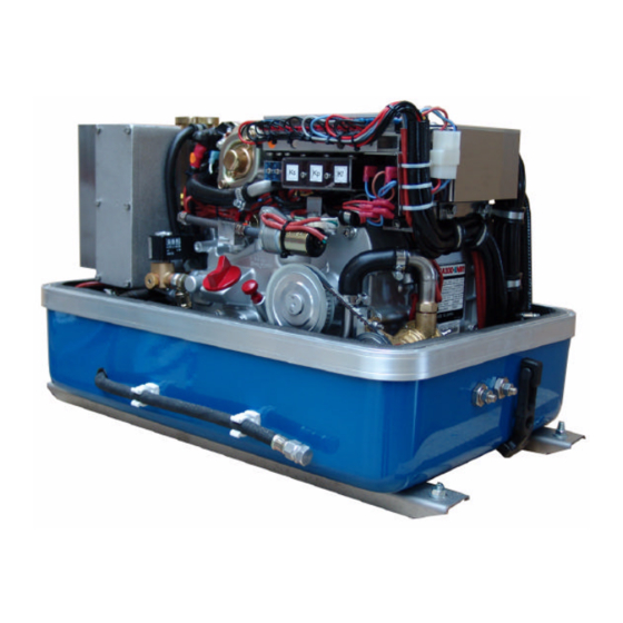
Operation manual Description of the generator and operation manual Marine Generator Panda AGT-DC 4000 PMS Super silent technology 24V - 140A / 4kW Icemaster Fischer Panda... - Page 2 Icemaster GmbH Panda generators Generators Fischer Panda FISCHER GENERATORS have been manufactured since 1978 and are a well-known brand for first class diesel gene- rators with especially effective sound-insulation. Fischer has been one of the leading manufacturers in respect of quality and know-how during this period.
- Page 3 Upgrades Far advantages: By your full information Fischer Panda technicians can give you fast assistance, since 90% of the disturbances result from errors in the periphery. Problems due to errors in the installation can be recognized in the apron.
-
Page 4: Safety Instructions
Safety Instructions The electrical Installations may only be carried out be trained and tested personnel! The generator may not be taken into use with the cover removed. The rotating parts (belt-pulley, belts, etc) must be so covered and protected do that there is no danger to life and body! If a sound insulation covering must be produced at the place of installation, then well-placed signs must show that the generator can only be switched on with a closed capsule. - Page 5 CAUTION! The AGT-generator is not allowed to be connected to an inverter (without batteries)! The Inverter generates voltage peaks, which can destroy the rectifier diodes of the generator! A battery must always be connected to the inverter as a capacity! ≥...
- Page 6 Measures to the fire protection. All construction units in the environment of energized parts, which carry more than 50 Amp., must be fire protection- moderately secured. All junction points at the energized parts must be examined regularly on heating up (infrared thermometers). Safety Instrictions for the Handling with Batteries These instructions must be noticed additionally to the instructions of the battery manufacturer: •...
-
Page 7: Table Of Contents
Table of contents The Panda Generator ......................3 A.1 Description of the Generator ....................3 A.1.1 Right Side View ......................... 3 A.1.2 Left Side View ........................... 4 A.1.3 Front View ..........................5 A.1.4 Back View..........................6 A.1.5 View from Above ........................7 A.2 Details of functionl units ...................... - Page 8 Page 2 Panda PMS AGT-DC 4000 - 24V - Table of contents...
-
Page 9: The Panda Generator
The Panda Generator A. The Panda Generator A.1 Description of the Generator A.1.1 Right Side View 01) Terminal block for remote control panel, fuses and 07) Connection starter battery plus (+) relays 08) Sound cover base part 02) Cooling water tank 09) Raw water inlet 03) Toothed belt 10) Engine Kubota EA300... -
Page 10: Left Side View
The Panda Generator A.1.2 Left Side View 01) Generator housing with coil 07) Sound cover base part 02) Water-cooled exhaust elbow 08) Ventilation valve 03) Thermo-switch at exhaust elbow 09) Injection nozzle 04) Raw water injection pipe 10) Suction port at air suction housing 05) Coolant pipe, water tank - heat exchanger 11) Cooling water tank 06) Exhaust outlet... -
Page 11: Front View
The Panda Generator A.1.3 Front View 02 03 01) Solenoid switch for starter motor 10) Pulley 02) Starter motor 11) Actuator 03) Oil pressure switch 12) Oil dipstick 04) Electrical fuses (blue=15A, white=10A) 13) Engine oil filler neck 05) Start relay Ks 14) Fuel solenoid valve 06) Glow-plug relay K2 15) Oil drain hose... -
Page 12: Back View
The Panda Generator A.1.4 Back View 18 17 15 14 01) Coolant pipe 12) Thermo-switch at exhaust elbow 02) Generator front cover 13) Cover for DC/DC-converter 03) Generator housing with coil 14) Connection for fuel OUT 04) Starter motor 15) Connection for fuel IN 05) Thermo-switch at engine 16) Cable for voltage sense 06) Coolant filler neck... -
Page 13: View From Above
The Panda Generator A.1.5 View from Above 01) Cooling water filler neck 10) Diode plate under protection cover 02) Cooling water tank 11) Terminal block for remote control panel, fuses and 03) Water-cooled exhaust elbow relays 04) Thermo-switch at exhaust elbow 12) Starter motor 05) Exhaust outlet 13) Fuel solenoid valve... -
Page 14: Details Of Functionl Units
The Panda Generator A.2 Details of functionl units A.2.1 Remote control panel 01) Betriebsstundenzähler 05) Leuchte für Betriebszustand 02) Leuchte für Motortemperatur 06) Generator „Start“-Taste 03) Leuchte für Öldruckleuchte 07) Panel „Stand by“-Taste 04) Leuchte für Batterieladespannung Fig. A.1: Remote control panel Automatic Start Option An automatic start option is available as an accessory. -
Page 15: Components Of Cooling System (Raw Water)
The Panda Generator A.2.2 Components of Cooling System (raw water) Raw water inlet The diagram shows the supply pipes for the generator. The connection neck for the raw water connection is shown on the left hand side. The cross-section of the intake pipe should be nominally larger than the generator connection. - Page 16 The Panda Generator Ventilation valve A siphon must be installed if the generator sinks below the water line because of the rocking of the boat, even if it is only for a short period of time. A hosepipe on the generator casing has been produced for this.
-
Page 17: Components Of Cooling Systems (Freshwater)
The Panda Generator A.2.3 Components of Cooling Systems (Freshwater) Cooling water filler neck The cooling water filler neck is situated at colling water tank and only used, when the generator is initially started. Since the generator is normally already fil- led with cooling water, these components are only by the user, if repairs are to be carried out. - Page 18 The Panda Generator Internal cooling water pump The diesel motor cooling water pump (see arrow) aids the circulation of the internal freshwater system. Fig. A.10: Internal cooling water pump Ventilation valve cooling water pump The ventilation screw above the cooling water pump casing may not be opened, whilst the generator is running.
- Page 19 The Panda Generator Coolant pipe, dioden plate - engine Fig. A.13: Coolant pipe Coolant outtake engine The coolant gets below of the engine out into the heat exchanger. Fig. A.14: Cooant outtake engine Ventilation pipe Fig. A.15: Ventilation pipe Panda PMS AGT-DC 4000 - 24V - Chapter A: The Panda Generator Page 13...
-
Page 20: Components Of The Fuel System
The Panda Generator A.2.4 Components of the Fuel System External fuel pump The Panda generator is always supplied with an external, electrical (12 V of DC) fuel pump. The fuel pump must be always installed in the proximity of the tank. The electrical connections with the lead planned for it are before-installed at the generator. - Page 21 The Panda Generator Injection nozzle If the engine does not start after the venti- lation, the fuel injection line must be deae- rated. Fig. A.19: Injection nozzle Glow plug The glow plug serve the pre-chamber for the heating with cold start. The heat-treat fixture must be operated, if the tempera- ture of the generator is under 16°C.
-
Page 22: Components Of Combustion Air
The Panda Generator A.2.5 Components of Combustion Air Air suction openings at the sound cover The sound cover is provided at the upper surface with drillings, through which the combustion air can influx. It must be consistently paid attention that the generator is installed in such a way that from no water can arrive into the pro- ximity of these air openings. -
Page 23: Components Of The Electrical System
The Panda Generator Exhaust elbow After the combustion air was led through the engine it occurs into the water-cooled exhaust elbow. On the top side the pipe union for the internal raw water circle is to be seen. Fig. A.24: Exhaust elbow Exhaust outlet Connect the exhaust pipe with the water lock. - Page 24 The Panda Generator Passage for battery cable The battery cables of the battery bank must be laid through this passage to the clamps at the diode plate. Fig. A.27: Passage Clamps for battery cable 1. Clmap (+) for battery cable (+) 2.
- Page 25 The Panda Generator Starter motor 1. Starter motor and 2. Solenoid switch The Diesel engine is electrically started. On the top of the engine is accordingly the electrical starter with the solenoid switch. Fig. A.30: Starter motor Actuator for speed regulation The generator voltage is determined by progressive speed control through "VCS"...
- Page 26 The Panda Generator Diode plate Fig. A.33: Diode plate Terminal block for remote control panel, fuses and relays F1 fuse 15A for release relay F2 fuse 15A for DC-system F2 fuse 10A for AC-system Ks relay for starter motor K2 relay for plow plug K3 relay for fuel pump K4 Release relay Fig.
-
Page 27: Sensors And Switches For Operating Surveillance
The Panda Generator A.2.7 Sensors and switches for operating surveillance Thermo-switch at engine The thermo-switch at the engine is used for monitoring the engine temperature. Fig. A.36: Thermo.switch at engine Thermo-switch at exhaust connection If the impeller pump drop out and delive- res no more seawater, the exhaust con- nection becomes extremely hot. - Page 28 The Panda Generator Oil pressure switch In order to be able to monitore the lubrica- ting oil system, an oil pressure switch is built into the system. Fig. A.39: Oil pressure switch Thermo-switch on the (-)-bar Fig. A.40: Thermo-switch on the (-)-bar Thermo-switch on the (+)-bar Fig.
-
Page 29: Components Of The Oil Circuit
The Panda Generator A.2.8 Components of the Oil Circuit Oil filler neck with cap Please pay attention that the filler necks are always well locked after filling in engine oil. Consider also the references to the engine oil specification. Fig. A.42: Oil filler neck Oil dipstick At the dipstick the permissible level is indi- cated by the markings "maximum"... -
Page 30: External Components
The Panda Generator Oil drain hose The Panda generator is equipped that the engine oil can be drained over an drain hose. The generator should be always installed therefore that a collecting basin can be set up deeply enough. If this is not possible, an electrical oil drain pump must be installed. -
Page 31: Operation Instructions
The Panda Generator A.3 Operation Instructions A.3.1 Daily routine checks before starting 1. Oil Level Control (ideal level: MAX). AtTTENTION! OIL PRESSURE CONTROL! True, the diesel motor automatically switches off when there is a lack of oil, but it is very damaging for the motor, if the oil level drops to the lowest limit. -
Page 32: Starting Generator
The Panda Generator A.3.2 Starting Generator 1. If necessary, open the fuel valve. 2. If necessary, close the main battery switch. 3. Check if all the consumers have been switched off. The consumers are switched off, before the generator is switched off. The generator is not to be started with con- sumers connected.
Need help?
Do you have a question about the Panda AGT-DC 4000 PMS and is the answer not in the manual?
Questions and answers