
Subscribe to Our Youtube Channel
Related Manuals for Fischer Panda AGT-DC 11000 PMS


Summary of Contents for Fischer Panda AGT-DC 11000 PMS
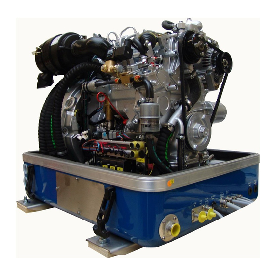
- Page 1 Manual Description of the generator - Installation andd operation manual Marine Generator Panda PMS AGT-DC 11000 Super silent technology 56,7V - 187A / 10,6kW Battery system 48V - I = 150A cont Fischer Panda GmbH...
-
Page 2: Current Revision Status
Duplication and change of the manual is permitted only in consultation with the manufacturer! Fischer Panda GmbH, 33104 Paderborn, reserves all rights regarding text and graphics. Details are given to the best of our knowledge. No liability is accepted for correctness. Technical modifications for improving the product without previous notice may be undertaken without notice. -
Page 3: Table Of Contents
Table of contents Current revision status ......................2 Safety first ..........................6 Tools ............................7 Safety Precautions ....................... 10 5 Safety steps to follow if someone is the victim of electrical shock ......13 WHEN AN ADULT STOPS BREATHING................14 The Panda Generator.................... - Page 4 Table of contents B.5.1 Installation of the standard exhaust system ............... 59 B.5.2 Exhaust / water separator ....................60 B.5.3 Installation exhaust/water separator .................. 61 B.6 Fuel system installation ....................63 B.6.1 General references ......................63 B.6.2 The electrical fuel pump ..................... 64 B.6.3 Connection of the fuel lines at the tank ................
- Page 5 Table of contents Troubleshooting ......................96 Engine oil specification ....................100 Coolant specifications ....................101 Dimensions ........................102 Revision status ........................104 Hardware and Software revision..................104 General operation ...................... 105 A.1 Panel AGT Control 145x100mm .................. 105 A.2 Reverse Side ......................... 106 A.3 Running modes - Automatic mode, manual mode and power save mode .....
- Page 6 Table of contents D.1 Hole Pattern 145x100mm ..................... 125 D.2 Hole Pattern 130x120mm ..................... 126 VCS-AGT-U/I........................127 A.1 VCS-AGT-U/I Versions ....................127 A.2 Voltage control system ....................127 A.2.1 Gerneral working of the VCS ................... 129 A.2.2 Safety instructions for the voltage control ................ 129 Battery monitor in DIN-tracks housing (RE9517) ............131 A.1 Safety instructions .......................
- Page 7 3500 kW from the main machine) Fischer Panda GmbH, 33104 Paderborn, reserves all rights regarding text and graphics. Details are given to the best of our knowledge. No liability is accepted for correct- ness. Technical modifications for improving the product without previous notice may be undertaken without notice. Before installation, it must be ensured that the Pictures,...
-
Page 8: Safety First
Safety first These symbols are used throughout this manual and on labels on the maschine itself to warn of the possibility of per- sonal injutry. Read these instructions carefully. It is essential that you read the instructions and safety regulations before you attempt to assemble or use unit. -
Page 9: Tools
Tools This symbols are used throughout this manual to show which tool must be used at maintenance or installation. Spanners X = number of spanner Hook wrench for oil filter Screw driver, for slotted head screws and for recessed head screws Multimeter, multimeter with capacitor measuring Infrared temperature mesuring pistol Current clamp (DC for synchron generators;... - Page 10 Socket wrench set Hexagon wrench keys...
- Page 11 2. The installation certificate must be despatched within two weeks of use to Fischer Panda. 3. The official guaranty confirmation will be completed by Fischer Panda after receipt and sent to the customer. 4. A guaranty must be shown to make any claims.
-
Page 12: Safety Precautions
Safety Precautions The electrical Installations may only be carried out be trained and tested personnel! The generator may not be taken into use with the cover removed. The rotating parts (belt-pulley, belts, etc) must be so covered and protected do that there is no danger to life and body! If a sound insulation covering must be produced at the place of installation, then well-placed signs must show that the generator can only be switched on with a closed capsule. - Page 13 CAUTION! The AGT-generator is not allowed to be connected to an inverter (without batteries)! The Inverter generates voltage peaks, which can destroy the rectifier rectifiers of the generator! A battery must always be connected to the inverter as a capacity! ≥...
- Page 14 Measures to the fire protection. All construction units in the environment of energized parts, which carry more than 50 Amp., must be fire protection- moderately secured. All junction points at the energized parts must be examined regularly on heating up (infrared thermometers). Safety Instrictions for the Handling with Batteries These instructions must be noticed additionally to the instructions of the battery manufacturer: •...
-
Page 15: Safety Steps To Follow If Someone Is The Victim Of Electrical Shock
5 Safety steps to follow if someone is the victim of electrical shock Do not try to pull or grab the individual. Send for help as soon as possible. If possible, turn off the electrical power. If you cannot turn off the electrical power, pull, push, or lift the person to safety using a wooden pole, rope, or some nonconductive material. -
Page 16: When An Adult Stops Breathing
WHEN AN ADULT STOPS BREATHING WARNING DO NOT attempt to perform the rescue breathing techniques provided on this page, unless certified. Performance of these techniques by uncertified personnel could result in further injury or death to the victim. Does the Person Respond? Shout, "Help!"... -
Page 17: The Panda Generator
The Panda Generator A. The Panda Generator A.1 Type ID plate at the Generator Fig. A.1-1: Type ID plate Fig. A.1-2: Discription type plate 18.12.08 AGT-DC_11000_48V_PMS_eng.R01 - Chapter A: The Panda Generator Page 15... -
Page 18: Description Of The Generator
The Panda Generator A.2 Description of the generator A.2.1 Right side view 01) Water-cooled exhaust elbow 11) Sound cover base part 02) Starter motor 12) Cooling water return hose 03) Thermo-switch exhaust elbow 13) Generator housing with coil 04) Ventilation pipe to external cooling water expansion tank 14) Connections for external cooling water expansion tank 05) Rectifier 15) Exhaust output... -
Page 19: Left Side View
The Panda Generator A.2.2 Left side view 01) Air suction housing with air filter 13) Power relays 02) Raw water intake hose 14) Fuses for voltage sense, AC-voltage (3x1,6A) and failure 03) Actuator for rpm-regulation bypass switch 04) Connection external ventilation valve 15) Sound cover base part 05) Passage for battery bank cable 16) Raw water intake... -
Page 20: Front View
The Panda Generator A.2.3 Front view 10 11 01) Ventilation screw internal cooling water pump 12) Oil drain hose 02) Stop solenoid 13) Cable AGT-control panel 03) Pulley for internal cooling water pump 14) Cable voltage control VCS 04) V-belt 15) Cable voltage sense (clamp 7+8) 05) Fuel filter 16) Cable shunt measurement (clamp 9+10) -
Page 21: Back View
The Panda Generator A.2.4 Back view 01) Rectifier 07) In-flow from external cooling water expansion tank 02) Water-cooled exhaust elbow 08) Return to external cooling water expansion tank 03) Injection hose raw water 09) Connection external ventilation valve 04) Generator front cover 10) Sound cover base part 05) Exhaust pipe 11) Cooling water connection block... -
Page 22: View From Above
The Panda Generator A.2.5 View from above 14 15 01) Rectifier 09) Air suction housing with air filter 02) Exhaust connection 10) Induction elbow 03) Ventilation hose to external expansion tank 11) Actuator 04) Water-cooled exhaust elbow 12) Fuel solenoid valve 05) Valve cover 13) Stop solenoid 06) Oil filler neck... -
Page 23: Details Of Functional Units
The Panda Generator A.3 Details of functional units A.3.1 Components of cooling system (raw water) Fig. A.3.1-1: Cooling system raw water 18.12.08 AGT-DC_11000_48V_PMS_eng.R01 - Chapter A: The Panda Generator Page 21... - Page 24 The Panda Generator Raw water intake The diagram shows the supply pipes for the generator. The connection neck for the raw water connection is shown on the left hand side. The cross-section of the intake pipe should be nominally larger than the generator connection.
- Page 25 The Panda Generator Rectifier The raw water cools the rectifier and dio- des. and is then lead to the oil cooler. Fig. A.3.1-5: Bypass Heat exchanger Separates the raw water system from the freshwater system. Fig. A.3.1-6: Heat exchanger Ventilation valve A siphon must be installed if the generator sinks below the water line because of the rocking of the boat, even if it is only for a...
- Page 26 The Panda Generator Cooling water injector port The injection point for the marine genera- tor water-cooled exhaust system is situa- ted at the exhaust connection pieces. The exhaust connections must be regularly checked for signs of corrosion. Fig. A.3.1-8: Cooling water injector port Page 24 AGT-DC_11000_48V_PMS_eng.R01 - Chapter A: The Panda Generator 18.12.08...
-
Page 27: Components Of Cooling System (Freshwater)
The Panda Generator A.3.2 Components of cooling system (freshwater) Fig. A.3.2-1: Cooling system fresh water 18.12.08 AGT-DC_11000_48V_PMS_eng.R01 - Chapter A: The Panda Generator Page 25... - Page 28 The Panda Generator Ventilation pipe The ventilation pipe at the water-cooled exhaust manifold leads to the external expansion tank. This pipe only serves as a ventilation pipe, if both pipes are to be connected to the external expansion tank (ventilation pipe and intake pipe). Fig.
- Page 29 The Panda Generator Heat exchanger Separates the raw water system from the freshwater system. Fig. A.3.2-5: Heat exchanger Cooling water injection A.) To the thermostat housing B.) From the external expansion tank C.) From the heat exchanger The intake pipe from the external cooling water expansion tank is connected to the point shown with „B“.
- Page 30 The Panda Generator Ventilation screw cooling water pump The ventilation screw above the cooling water pump casing may not be opened, whilst the generator is running. If this occurs by mistake, air will be drawn through the opening. Extensive ventilation of the whole system is then necessary.
-
Page 31: Components Of The Fuel System
The Panda Generator A.3.3 Components of the fuel system Fig. A.3.3-1: Fuel system 18.12.08 AGT-DC_11000_48V_PMS_eng.R01 - Chapter A: The Panda Generator Page 29... - Page 32 The Panda Generator External fuel pump The Panda generator is always supplied with an external, electrical (12 V of DC) fuel pump. The fuel pump must be always installed in the proximity of the tank. The electrical connections with the lead plan- ned for it are before-installed at the gene- rator.
- Page 33 The Panda Generator Fuel solenoid valve The fuel solenoid valve opens automati- cally if „START“ is pressed on the remote control panel“. The solenoid closes, if the generator is switched to „OFF“ position. It takes a few seconds before the genera- tor stops.
- Page 34 The Panda Generator Stop solenoid for engine stop Some model are additional equipped with an stop solenoid. The generator is stop- ped by the co-operation of the stop sole- noid immediately after switching off. The adjustment of the stop solenoid must always be checked, in order to be sure that the stop lever can move also during the operation freely and is not under pre-...
-
Page 35: Components Of Combustion Air
The Panda Generator A.3.4 Components of combustion air Fig. A.3.4-1: Combustion air system 18.12.08 AGT-DC_11000_48V_PMS_eng.R01 - Chapter A: The Panda Generator Page 33... - Page 36 The Panda Generator Air suction openings at the sound cover The sound cover is provided at the base part with drillings, through which the com- bustion air can influx. It must be consistently paid attention that the generator is installed in such a way that from no water can arrive into the pro- ximity of these air openings.
- Page 37 The Panda Generator Induction elbow The figure shows the induction elbow at the combustion engine. At the front of this induction elbow you can see the hose connection between air suction housings and induction elbow. The air filter must be checked, if this hose pulls together at ope- ration.
- Page 38 The Panda Generator Exhaust connection at the exhaust elbow Raw water from the external cooling circle is fed here. Fig. A.3.4-8: Exhaust port Exhaust outlet Connect the exhaust pipe with the water lock. Fig. A.3.4-9: Exhaust outlet Page 36 AGT-DC_11000_48V_PMS_eng.R01 - Chapter A: The Panda Generator 18.12.08...
-
Page 39: Components Of The Electrical System
The Panda Generator A.3.5 Components of the electrical system Fig. A.3.5-1: Electrical system 18.12.08 AGT-DC_11000_48V_PMS_eng.R01 - Chapter A: The Panda Generator Page 37... - Page 40 The Panda Generator Connection starter battery 1. Cable for starter battery (-) 2. Cable for starter battery (+) During the connection to the starter bat- tery it must be always ensured that the contact is perfectly guaranteed. See wiring diagram Fig.
- Page 41 The Panda Generator Electrical connections for control At the front of the generator also all remai- ning cables for the electrical connections are depending upon type. The allocation of the connections result from the plan for the AC-Control box. See here: 1.
- Page 42 The Panda Generator Alternator All Panda generators from Panda 6.000 are provided with its own charge system for the 12V DC mains. This alternator is powered over a v-belt together with the internal cooling water pump. The 12V charge system may be used only for the generator-own starter battery.
- Page 43 The Panda Generator Terminal block for remote control cable with fuses and power relays 01. Fuses 02. Power relays See wiring diagram Fig. A.3.5-11: Terminal block Time relay for stop solenoid 1. Time relay See wiring diagram Fig. A.3.5-12: Time relay 18.12.08 AGT-DC_11000_48V_PMS_eng.R01 - Chapter A: The Panda Generator Page 41...
-
Page 44: Sensors And Switches For Operating Surveillance
The Panda Generator A.3.6 Sensors and switches for operating surveillance Thermo-switch at cylinder head The thermo-switch at the cylinder head serves the monitoring of the generator temperature. All thermo-switches for the generators from Panda 6.000 upward are two-pole and laidout as "openers". T=110°C NC for control panel alarm T=130°C NC for redundance, direct switch for fuel relays... - Page 45 The Panda Generator Thermo-switch coil 4x165° C NC For the protection of the generator coil there are three NTC´s inside the coil, which are for inser- ted parallel and safety's sake independently from each other. Fig. A.3.6-4: Thermo-switch coil Oil pressure switch In order to be able to monitore the lubrica- ting oil system, an oil pressure switch is built into the system.
- Page 46 The Panda Generator Failure bypass switch The failure bypass switch offers the possi- bility of starting the generator if the electri- cal control switched off due to an error in the cooling system by overheating. Fig. A.3.6-7: Failure bypass switch Page 44 AGT-DC_11000_48V_PMS_eng.R01 - Chapter A: The Panda Generator 18.12.08...
-
Page 47: Components Of The Oil Circuit
The Panda Generator A.3.7 Components of the oil circuit Fig. A.3.7-1: Lubrication system Oil filler neck with cap Normally the filler neck for the engine oil is on the top side of the valve cover. At numerous generator types a second filler neck is attached additionally at the opera- ting side. - Page 48 The Panda Generator Oil dipstick At the dipstick the permissible level is indi- cated by the markings "maximum" and "minimum". The engine oil should be never filled up beyond the maximum con- ditions. Fig. A.3.7-3: Oil dipstick Oil filter The oil filter should be exchanged with an oil change.
-
Page 49: External Components
The Panda Generator A.3.8 External components Voltage control VCS The figure shows the control printed board for the VCS voltage regulation. Over this control printed board the control signals are given for the actuator for speed regu- lation. On the VCS board are also adjust- ment possibilities control... -
Page 50: Operation Instructions
The Panda Generator A.4 Operation instructions A.4.1 Preliminary remarks Starter Battery Adequate batteries are installed for extreme winter conditions. Unless the generator is being run frequently for extended (over 1 hour) periods, it is recommended that the starter battery is regu- larly charged by a suitable external battery-charging device, at least every 2 months. -
Page 51: Starting Generator- See Remote Control Panel Datasheet
The Panda Generator A.4.2 Daily routine checks before starting (Forts.) 5. Check all Hose Connections and Hose Clamps are Leakage. Leaks at hose connections must be immediately repaired, especially the raw water impeller pump. It is certainly possible that the raw water impeller pump will produce leaks, depending upon the situation. (This can be caused by sand particles in the raw water etc.) In this case, immediately exchange the pump, because the dripping water will be sprayed by the belt pulley into the sound insulated casing and can quickly cause corrosion. -
Page 52: Starting The Generator By A „Failure Bypass Switch
The Panda Generator A.4.5 Starting the generator by a „Failure bypass switch“ ATTENTION: If the generator switches itself off at operation for temperature reasons, it must be exami- ned immediately, which the cause is. That can be an error at the cooling system, drive belt or any error in the range of the outside cooling system. -
Page 53: Installation Instructions
Installation Instructions B. Installation Instructions B.1 Placement B.1.1 Placement and basemount Since Panda generators have extremely compact dimensions they can be installed in tight locati- ons, attempts are sometimes made to install them in almost inaccessible places. Please consider that even almost maintenance-free machinery must still remain accessible at least at the front (drive belt, water pump) and the service-side (actuator, dipstick). -
Page 54: Generator Connections - Scheme
Installation Instructions B.2 Generator connections - scheme The generator comes supplied with all supply lines (i.e. electric cables, fuel lines etc.) already connected to the motor and generator. The supply lines are fed through the capsule's front base panel and are shielded at the capsule inlets with water-proof grommets. All electrical connections, cable types and sizes must comply to the appropriate regulati- ons. -
Page 55: Cooling System Installation - Raw Water
Installation Instructions B.3 Cooling system installation - raw water B.3.1 General references The genset should have its own raw water (coolant water) inlet and should not be connected to any other engine systems. Ensure that the following installation instructions are complied with: Avoid galvanic corrosion For the avoidance of galvanic corrosion the chapter "Service instruction for marine gensets (cor- rosion protection)“... -
Page 56: Installation Above Waterline
A repair is then very expensive. Replacement impeller and also a spare pump should always be on board. The old pump can be sent back to Fischer Panda, where it is then economically overhauled completely. 1. Raw water filter 2. Water cock 3. -
Page 57: Installation Below Waterline
Installation Instructions B.3.5 Installation below waterline If the generator can not be attached at least 600mm over the waterline, a vent valve must be installed into the raw water line. With location beside the "midship line" a possible hee- ling must be considered! The water hose for the external vent valve at the back of the sound cover splits on the pres- sure side of the pump and at both ends in each case exten- ded with a connecting nipple by a hose end. -
Page 58: Raw Water Cooling
Installation Instructions B.3.6 Raw water cooling 1. Raw water pump 5. Oil cooler 2. Raw water in 6. Heat exchanger 3. Impellerfilter 7. External ventilation valve 4. Rectifier 8. Raw water out Fig. B.3.6-1: Raw water cooling system Page 56 AGT-DC_11000_48V_PMS_eng.R01 - Chapter B: Installation Instructions 18.12.08... -
Page 59: The Freshwater - Coolant Circuit
Installation Instructions B.4 The freshwater - coolant circuit B.4.1 Position of the external cooling water expansion tank The Panda generator is normally sup- plied with an additional, external cool- ing water expansion tank. This tank must be installed in such a way that its lower edge is at least 500mm more highly arranged than the upper edge of the sound cover. -
Page 60: Scheme For Freshwater Circuit At Two Circuit Cooling System
Installation Instructions B.4.3 Scheme for freshwater circuit at two circuit cooling system 1. Thermostat housing 4. Freshwater-cooled exhaust elbow 2. Internal water pump 5. External cooling water expansion tank 3. Heat exchanger Fig. B.4.3-1: Fresh water cooling system Page 58 AGT-DC_11000_48V_PMS_eng.R01 - Chapter B: Installation Instructions 18.12.08... -
Page 61: Watercooled Exhaust System
Installation Instructions B.5 Watercooled exhaust system By injecting the outlet raw water into the exhaust manifold, the exhaust gases are cooled and the noise emissions from the exhaust system are reduced. B.5.1 Installation of the standard exhaust system The generator exhaust system must remain completely independent and separate from the exhaust system of any other unit(s) on board. -
Page 62: Exhaust / Water Separator
Additionally there is component at Fischer Panda, which exercise both functions of a "exhaust goose neck", and the water separa- tion. With this "exhaust/water separator" the cooling water is derived over a separate pipe. The- reby the exhaust noises at the exterior of the yacht are strongly decreased. -
Page 63: Installation Exhaust/Water Separator
Installation Instructions B.5.3 Installation exhaust/water separator If the exhaust/water separator was sufficiently highly installed, a goose neck is no longer neces- sary. The exhaust/water separator fulfills the same function. If the "Supersilent" exhaust system were installed correctly, the generator will not disturb your boat neighbour. The exhaust noise should be nearly inaudible. - Page 64 Installation Instructions Example of an unfavorable installation: - water lock not deeply enough under the hights level of the generator - distance water lock to exhaust/water separator too largely Fig. B.5.3-2: Unfavorable installation - example Page 62 AGT-DC_11000_48V_PMS_eng.R01 - Chapter B: Installation Instructions 18.12.08...
-
Page 65: Fuel System Installation
Installation Instructions B.6 Fuel system installation B.6.1 General references Inside the generator capsule itself, there is the fuel filter installed (Exception Panda 4500). Addi- tional fuel filters (with water seperator) must be mounted outside the capsule in easily accessible places in the fuel lines between the tank intake fuel pump and the diesel motor's fuel pump. Generally forward and return fuel flow pipes must be mounted to the diesel tanks. -
Page 66: The Electrical Fuel Pump
Installation Instructions B.6.2 The electrical fuel pump Electrical fuel pump With the Panda generator is usually supp- lied an external, electrical fuel pump (12V DC). The fuel pump must be installed close at the fuel tank. The electrical con- nections are preloaded at the generator with the lead planned. -
Page 67: Position Of The Pre-Filter With Water Separator
Installation Instructions B.6.4 Position of the pre-filter with water separator Additionally to the standard fine filter a pre-filter with water separator must be installed outside of the sound cover in the fuel system line. (is not included in deliv- ery.) Fig. -
Page 68: Generator 12V Dc System-Installation
Installation Instructions B.7 Generator 12V DC system-installation The Panda has its own dynamo to charge a 12V starter battery. It is recommended to install an additional starter battery for the generator. The generator is then independent from the remaining battery set. This enables you to start the genset at any time with its own starter battery even if the other batteries are discharged. -
Page 69: Installation Panda Agt 48V-System
Installation Instructions B.7.2 Installation Panda AGT 48V-system ATTENTION! Before the electrical system is installed, READ the section ,“Safety Precauti- ons,” on page 10 FIRST! Be sure that all electrical installations (including all safety systems) comply with all required regulations of the regional authorities. This includes lightnening conductor, personal protection switch etc. -
Page 70: Voltage Control System - See Vcs Datasheet
Installation Instructions Electrical fuses It is absolutely essential that the electrical system installation is inspected by a qualified electrical technician. The generator should have its own AC input electrical fuses. The fuses should be sized such that the rated current of the generator on each of the individual phases is not excee- ded by more than 25%. -
Page 71: Maintenance Instructions
Maintenance Instructions C. Maintenance Instructions ATTENTION! Before working on the System read the section “Safety Precautions,” on page 10. C.1 General maintenance instructions C.1.1 Checks before starting • Oil level • Cooling system leaks • Visual check for any changes, leaks oil drain system, v-belt, cable connections, hose clips, air filter, fuel lines Once a month •... -
Page 72: Oil Change Procedure
Maintenance Instructions C.3 Oil change procedure Oil drain hose Open the passage for the oil drain hose and pull out the hose. Fig. C.3-1: Oil drain hose Oil drain screw The oil can be discharged by opening the oil drain screw. For countering use a second wrench. - Page 73 Maintenance Instructions Oil filter change The oil filter can be loosen with an oil filter strap. Fig. C.3-4: Oil filter Oil filter gasket Before the insertation of the new oil filter the gasket should be coated with some- thing oil. Tighten the oil filter only by hand.
-
Page 74: Ventilating The Fuel System
The prescribed fil- ling level may not exceed the „Max“ mar- king. Fischer Panda recommends 2/3 oil level. Fig. C.3-7: Oil dipstick C.4 Ventilating the fuel system Normally, the fuel system is designed to bleed out air itself i.e. as soon as the electric starter motor starts operation the fuel pump starts working and the fuel system will be ventilated after some time automatically. -
Page 75: Replace The Fuel Filter
Maintenance Instructions 3. After the fuel pump has been running 3 to 4 minutes because the failure bypass switch has been pushed down the ventilation screw of the solenoid valve has to be unscrewed. When ope- ning the screw one has to carry on pushing the switch. -
Page 76: Checking The Water Separator In The Fuel Supply
Maintenance Instructions C.4.2 Checking the water separator in the fuel supply The pre-filter with water separator has a cock at its lower surface, with this cock the downward sunk water can be discharged. This is simply possible, water is heavier due to its density than the Diesel. -
Page 77: Ventilating Of The Coolant Circuit / Freshwater
Maintenance Instructions C.6 Ventilating of the coolant circuit / freshwater Special notes for the ventilation of the cooling system If the cooling water is drained or if other air should have arrived into the cooling system, it is necessary to ventilate the cooling system. This ventilation procedure must be repeated several times: ATTENTION ! Before opening the venilation points the generator must be stagnant !!! - Page 78 Maintenance Instructions Now the cooling water is only filled over the external expansion tank. This is connected by 2 hoses with the genset. The external expansion tank should be filled in the cold condition only up to maximally 20%. It is very important that a large extension space over the cooling water level remains. Repeat this procedure several times.
- Page 79 Maintenance Instructions Loosen the fixing screw above the alter- nator. Fig. C.7-1: Fixing screw - DC-alternator Loosen the fixing screw below the alterna- tor only a little bit. Fig. C.7-2: Fixing screw - DC-alternator Press the alternator to the direction of the thermostat housing.
-
Page 80: The Raw Water Circuit
Maintenance Instructions Stretch the v-belt by pulling the alternator back. The v-belt should be able to be pressing approx. 1cm with the thumb. Tighten the fixing srews above and below the alternator. Fig. C.7-4: V-belt C.8 The raw water circuit C.8.1 Clean raw water filter The raw water filter should be released regularly from arrears. -
Page 81: Causes With Frequent Impeller Waste
Maintenance Instructions C.8.2 Causes with frequent impeller waste The impeller of the cooling water pump must be regarded as wearing part. The life span of the impeller can be extremely different and exclusively depends on the operating conditions. The cooling water pumps of the PANDA generators are laid out in such a way that the number of revolutions of the pump lies low compared with other gensets. - Page 82 Maintenance Instructions Raw water pump on the front side of the genset. Fig. C.8.3-2: Raw water pump Remove the cover of the raw water pump by loosen the screws from the housing.. Fig. C.8.3-3: Raw water pump Mark the impeller, to make sure that these is used in the correct position at re-instal- lation.
- Page 83 Maintenance Instructions Check to the impeller for damage and replace it if necessary. Before the reinsertion into the housing the impeller should have been lubricated with glycerin or with a non-mineral oil based lubricant e.g. silicone spray. Fig. C.8.3-5: Impeller The impeller is attached to the pump wave (if the old impeller is used, pay attention to the before attached marking).
-
Page 84: Additional Maintenance
Maintenance Instructions C.9 Additional maintenance Furthermore in addition to the standards checks according to the manual following points of the generator have to be checked: • automatic shut down of the generator in case off high heating temperature This shall be done by disconnecting the thermo-switch of the heat sink. Next to the rectifier you will find a 2-pole connector. -
Page 85: Conservation At Longer Operation Interruption
Maintenance Instructions C.10 Conservation at longer operation interruption C.10.1Measures on preparation of the winter storage 1. Rinse raw water circuit with an anti-freeze solution, even if this contains a corrosion protection means. The raw water inlet must be removed at the water cock. Over a hose connector the anti-freeze protection mixture is to be sucked in from a container. -
Page 86: Initiation At Spring
Start generator and check the basic adjustments of the generator such as voltage, speed re- gulation etc.. • Check all switching off devices for function by operational procedures. Fischer Panda does not take over adhesion for possible damages! Page 84 AGT-DC_11000_48V_PMS_eng.R01 - Chapter C: Maintenance Instructions 18.12.08... -
Page 87: Replace The Water Pump
Maintenance Instructions C.11 Replace the water pump 1. Unscrew the water pump mounting screws (2), and remove the water pump (1) from the gear case cover. Use a spanner size 10mm. When reassembling • Apply liquid-type gasket (Three Bond 1215 or its equivalent) to both sides of the new water pump gasket. -
Page 88: Replace The Valve Cover Gasket
Maintenance Instructions C.12 Replace the valve cover gasket 1. Remove the valve cover cap nuts (3). Use a spanner size 10mm. 2. Remove the valve cover (1). 3. Check to see that the valve cover gasket (2) is defective. 4. Replace the valve cover gasket (3) with a new one. 5. -
Page 89: Adjustment Of The Valve Clearance
Maintenance Instructions C.12.1Adjustment of the valve clearance Valve Clearance Important: Valve clearance must be checked and adjusted when engine is cold. 1. Remove the head cover 2. Align the „1TC“ mark on the flyw- heel and projection (1) on the hou- sing so that the No. - Page 90 Maintenance Instructions Cylinder No. 2 cylinder 3 cylinder 4 cylinder Valve arrangement Adjustable cylinder Location of piston When piston is com- pression dead center When piston is overlap position Page 88 AGT-DC_11000_48V_PMS_eng.R01 - Chapter C: Maintenance Instructions 18.12.08...
-
Page 91: Generator Failure
Generator Failure D. Generator Failure ATTENTION! Before working on the System read the section “Safety Precautions,” on page 10. D.1 Overloading the generator Please ensure that the genset is not overloaded. An overload in the long term can harm the engine. - Page 92 Generator Failure 01. Fuel solenoid valve 02. Fuel injector pipe 03. Ventilation screw Fig. D.2.1-1: Fuel solenoid valve Stop solenoid for engine stop Fig. D.2.1-2: Stop solenoid Page 90 AGT-DC_11000_48V_PMS_eng.R01 - Chapter D: Generator Failure 18.12.08...
-
Page 93: Vcs Does Not Work - See Vcs Datasheed For Details
Generator Failure D.2.2 VCS does not work - See VCS datasheed for details For start problems one chief cause is that the VCS doen not work. Check: Is the shunt connection ok? Check polatrity! Is the main supply connection ok? Check polatrity! Does DP+ (VCS ON) lie on clamp 6 of the plug with 6 pins? Checking the fuse on the VCS printed circuit board. -
Page 94: Troubleshooting Table
Generator Failure D.2.5 Failure bypass switch ATTENTION: If the generator switches itself off at operation for temperature reasons, it must be exami- ned immediately, which the cause is. That can be an error at the cooling system, drive belt or any error in the range of the outside cooling system. With cooling water loss: Errors locate and cooling water refill. -
Page 95: F Tables
Tables F. Tables Technical data F.1.1 Technical data engine Model Kubota D 902 Type Vertical, water-cooled, 4-cycle diesel engine No. cylinders Bore [mm] Stroke [mm] 73,6 Total displacement [ccm] Combustion chamber Spherical type (E-TVCS) SAE NET intermittent (SAE J1349) at 3600rpm [kW] 17,5 SAE NET continuous (SAE J1349) at 3600rpm [kW] 15,2... -
Page 96: Technical Data Generator
Tables F.1.2 Technical data generator Generator AGT-DC 11000 PMS Generator type PM-Synchronous Generator Winding type Wiring mode Protection mode IP 44 Insulation class Nominal voltage 56,7 V Frequency 426 Hz Nominal speed -> 3200 rpm Max. current 187 A Apparent power... - Page 97 Tables Ø Cooling water conduit Ø Fuel conduit Ø Exhaust con- duit Fresh water Raw water Supply Return Generatortype [mm] [mm] [mm] [mm] [mm] Panda AGT-DC 11000 Table 3: Diameter of conduits Wiring. single phase, not tin-plated, PVC-isolated. allowed conrinuous current (reference point) nominal wire cross-section [mm²] at +30°C [A]...
-
Page 98: Troubleshooting
Tables Troubleshooting GENERATOR OUTPUT VOLTAGE TOO LOW If the generator delivers less than 24V current ("undervoltage"), there can be various reasons for this: Cause Solution Generator is overloaded. Reduce the electrical load. (Switch off load) Motor is not reaching the rated rpm. Refer to "motor faults"... - Page 99 Tables MOTOR TURNS OVER BUT DOES NOT START Cause Solution Stop solenoid valve not opening. Check wire connections and circuitry to solenoid valve. (ref. DC wiring diagram: Relay K2, Fuse) Fuel pump does not operate. Check fuel-filter and pump: clean if necessary. Lack of fuel.
- Page 100 Tables DROP IN THE SPEED OF THE MOTOR Cause Solution Too much oil. Drain oil. Lack of fuel. Check fuel supply system: - fuel filter, renew if necessary - check fuel pump - check fuel lines (bleed if necessary) Lack of intake air. Check air intake paths.
- Page 101 Tables SOOTY, BLACK EXHAUST Cause Solution Generator is overloaded. Check electrical load and switch off unnecessary load. Insufficient intake air. Check intake air filter; clean if necessary. Fuel injector nozzles faulty. Replace injector nozzles. Valve clearance incorrect. Readjust valve clearance to correct value (refer to Kubota-manual).
-
Page 102: Engine Oil Specification
Tables Engine oil specification Engine oil classification Operating range: The operating range of an engine oil is determined by SAE class. "SAE" is for the union of American engineers (Society of Automotives Engineers). The SAE class of an engine oil only informs over the viscosity of the oil (lar- ger number = more viscous, lower number = more highly liquidly) e.g. -
Page 103: Coolant Specifications
Use a mixture of water and antifreeze. The antifreeze needs to be suitable for aluminium. The antifreeze concen- tration must be regularly checked in the interests of safety. Fischer Panda recommend to use the product: GLYSANTIN PROTECT PLUS/G 48. Engine coolant automotive industry Product description Product name GLYSANTIN ®... -
Page 104: Dimensions
Tables Dimensions Fig. F.5-1: Dimensions Page 102 AGT-DC_11000_48V_PMS_eng.R01 - Chapter F: Tables 18.12.08... - Page 105 Panel AGT Control Manual Art Nr. 21..02.02.003H Art.Nr. 21.02.02.006H Fischer Panda GmbH...
-
Page 106: Revision Status
Revision status Document Aktuell: Panel AGT Control_Kunde_eng.R03 vom 18.12.08 Replace Panda AGT Control_Manual.R02 Revision Page Hardware and Software revision After turning on the panel the welcome screen will show the software revision. The hardware revision is printed on the reverse side of the panel Attention: Please note the safety remarks in your generator manual... -
Page 107: General Operation
General operation A. General operation A.1 Panel AGT Control 145x100mm 06. Button „ON/OFF“ 01. LED for temp. green/red 07. Button „down“ 02. LED for oil pressure green/red 08. Button „Enter“ 03. LED for fault green/red 09. Button „up“ 04. LED for mode Mode green/yellow 10. -
Page 108: Reverse Side
General operation A.2 Reverse Side 01. Clamp 1-9 04. Fuse 1,6A slow to blow 02. Clamp 10-16 05. Battery for real time clock 03. Clamp 17-22 06. Connector for Master-/Slave-Adapter Fig. A.2-1: Panel Reverse Side Seite 106 Panel AGT Control_Kunde_eng.R03 - Kapitel A: General operation 18.12.08... -
Page 109: Running Modes - Automatic Mode, Manual Mode And Power Save Mode
General operation A.3 Running modes - Automatic mode, manual mode and power save mode Switch on the Panel by pressing the „ON/OFF“ button. Advice: If the panel is switched on by an external signal (clamp 18 High(+Vbat), the panel can also only be switched off by this external signal. -
Page 110: Standby Modus
A.3.4 Power Save Modus After the power save time, which can be adjusted by the Fischer Panda Distributor, the panel will automatically switch into the Power save mode. The panel will be reactivated by pressing the "ENTER"-button for 1 sec. -
Page 111: Starting And Stopping The Generator
General operation A.4 Starting and Stopping the generator A.4.1 Starting the generator in the „Manual mode“ 1. Open the fuel valve (if necessary). 2. If necessary, close the main battery switch and open the sea lock (Marine version). 3. Press the „ON/OFF“-button (switch on the panel), or awaken the panel from the power save mode by pressing the „Enter“-button. -
Page 112: Starting The Generator In The „Automatic Mode
General operation A.4.2 Starting the generator in the „Automatic Mode“ 1. Open the fuel valve (if necessary) 2. If necessary, close the main battery switch and open the sea lock (Marine version). 3. Press the „ON/OFF“-button (switch on the panel) (Optional external „ON“... -
Page 113: Stopping The Generator
General operation A.4.3 Stopping the generator 1. In the "manual mode" the generator can be stopped either by pressing the "Start/Stop" button or by switching off the remote control panel. 2. In the „automatic mode“ the generator will be stopped by an external stop requirement (e.g. from the battery voltage control or an external signal). -
Page 114: Menu Tree
General operation A.5.1 Menu tree Fig. A.5.1-1: Menu tree Seite 112 Panel AGT Control_Kunde_eng.R03 - Kapitel A: General operation 18.12.08... -
Page 115: Explanation Of The Menu Table
General operation A.5.11Explanation of the menu table System Parameter -In the system parameters, all settings can be made, which are important for the user concerning the display System Parameter - Light - Setting of the general background light of the display in the operating mode of the panel Minimum value 0% - maximum value 100% - default value 100% System Parameter - Contrast - Setting of the contrast of the display in the operation mode and standby mode of the panel... -
Page 116: Error Message
"emergency stop" (see Capture A.6.1, “Type of Error „Emergency Stop“,” on page 115). Other configurations can be made by Fischer Panda, according to the application (e.g. DE-drive - also see “Type of Error „Delayed“” on Page 115.) The AGT Control Panel displays the error messages in different ways. -
Page 117: Type Of Error „Emergency Stop
General operation A.6.1 Type of Error „Emergency Stop“ The report for this error is activated. Fault-LED changes to red (at temperature errors or oil pressure errors the appropriate error LED ) The display changes to error display The generator stops immediately The external error output will be switched for approx. -
Page 118: Type Of Error „Deactivated
General operation A.6.4 Type of Error „Deactivated“ The report for this error is deactivated. - Fault-LED does not change to red (at temperature error or oil pressure error the appropriate fault LED) - No display of the error - Generator does not stop All error types, which are not needed in the generator / drive configuration can be deactivated. -
Page 119: Installation Of The Agt Control Panels
General operation A.7 Installation of the AGT Control Panels A.8 Clamps of the AGT Control Panel Connect the wires of the connection cable with the clamp of the AGT control according to its no. Clamp Name of clamp Function Application Vbat (operation voltage) operation voltage + (Automotive) Standard²... -
Page 120: Master-Slave Operation (In Preparation - Available 11/2008)
General operation In = +12/24VDC (+/- tolerance battery voltage): Panel-On (external panel Panel switched on, FlipFlop ON/OFF reset Optional³ switch on) In = open or 0V: Panel switched off BW-OK(failure battery voltage to GND: no errors NA Optional control) open: no mesurement voltage or over voltage or reset not possible to GND : VCS on and no voltage error loged: VCS-OK NA Optional... -
Page 121: Clamps Of The Master-Slave Adapter
General operation A.9.4 Clamps of the Master-Slave Adapter Master-Slave Conenction, Clamp X1 (reference point: Master) Clamp Signal Description At the slave, connect with Ground RX/TX Transmitter / receive path A 24 RX/TX Transmitter / receive path B 25 Ground (also apply the shield here one- sided) Fig. -
Page 122: Systemparameter Setting
General operation A.9.5 Systemparameter Setting For recording your preferential settings. Fig. A.9.5-1: Systemparameter settings Seite 120 Panel AGT Control_Kunde_eng.R03 - Kapitel A: General operation 18.12.08... -
Page 123: R03Installation/Tech. Documentation
.R03Installation/Tech. documentation B. .R03Installation/Tech. documentation B.1 Clamps Clamp Clamp name Funktion used as Vbat (12V) Battery voltage + (12V-Automotive) Standard Battery voltage - (12V-Automotive) Standard toGND : temperature OK temperature error Standard open: temperature error to GND : drive OK drive error Option open: drive errorr... - Page 124 .R03Installation/Tech. documentation to Vbat-F-S : Alarm on alarm/error out Option open (eith free wheeling diode): Alarm off to GND : Temperature OK cooling water temp. error Option open: cooling water temperature error Fig. B.1-1: Clamps Page 122 Panel AGT Control_Kunde_eng.R03 - Chapter B: .R03Installation/Tech. documentation 18.12.08...
-
Page 125: Installation
Installation C. Installation C.1 Wiring diagram Panda AGT Control Panel Fig. C.1-1: Wiring diagram 18.12.08 Panel AGT Control_Kunde_eng.R03 - Chapter C: Installation Page 123... -
Page 126: Technical Data Agt Control Panel
Installation C.2 Technical Data AGT Control Panel Panel Version Panel AGT Control 12VDC Panel AGT Control 24VDC Max. Current Consumption 190mA 290mA Standby Mode 75mA 95mA Energy Save Mode 20-35mA 23-30mA Temperature Area (-20) - 70° C / (-30) - 80° C Operation / Storage (pre-glow phase might be necessary) Max. -
Page 127: Measurements
Measurements D. Measurements D.1 Hole Pattern 145x100mm Fig. D.1-1: Hole Pattern 145x100mm 18.12.08 Panel AGT Control_Kunde_eng .R02 - Chapter D: Measurements Page 125... -
Page 128: Hole Pattern 130X120Mm
Measurements D.2 Hole Pattern 130x120mm Fig. D.2-1: Hole Pattern 130x120mm Page 126 Panel AGT Control_Kunde_eng.R02 - Chapter D: Measurements 18.12.08... -
Page 129: Vcs-Agt-U/I
VCS-AGT-U/I Fischer Panda Datasheet A. VCS-AGT-U/I A.1 VCS-AGT-U/I Versions Art. Nr.: Set point Art. Name F1RORE9627-012-212 VCS-AGT-U/I 12V= @60mV F1RORE9627-024-212 VCS-AGT-U/I 24V= @60mV F1RORE9627-036 VCS-AGT-U/I 36V= @60mV F1RORE9627-048 VCS-AGT-U/I 48V= @60mV F1RORE9627-072-212 VCS-AGT-U/I 72V= @60mV F1RORE9627-080-212 VCS-AGT-U/I 80V= @60mV auf Anfrage / on request... - Page 130 VCS-AGT-U/I Fischer Panda Datasheet 1. Terminals 9+10 2. Potentiometer for the charging current Fig. A.2-2: VCS view The VCS control is used for the adjustment of the number of revolutions of the engine and thus the voltage of the generator. It belongs to the accessories and is externally attached.
-
Page 131: Gerneral Working Of The Vcs
VCS-AGT-U/I Fischer Panda Datasheet A.2.1 Gerneral working of the VCS When the VCS is active (+12V on clamp 6) the VCS controls the actuator to reach the exact voltage. The mesurement voltage is taken from the generator by an shunt which has 60mV nominal. - Page 132 VCS-AGT-U/I Fischer Panda Datasheet Intentionally Blank Page 130 - Chapter A: VCS-AGT-U/I VCS-AGT-UI_eng.fm...
-
Page 133: Battery Monitor In Din-Tracks Housing (Re9517)
Battery monitor in DIN-tracks housing (RE9517) Fischer Panda Datenblatt/Datasheet Battery monitor in DIN-tracks housing (RE9517) Art Nr. see technical data Bez. Battery monitor Document Hardware Software Actual: Rev.2.0_05.06.2007 Rev.1.2_24.02.2004 Replace: Rev.1.0_24.02.2004 Rev.1.2_24.02.2004 Replaced by: -------------------------- -------------------------- -------------------------- A.1 Safety instructions... -
Page 134: Brief Description
Battery monitor in DIN-tracks housing (RE9517) Fischer Panda Datenblatt/Datasheet A.2 Brief description Automatic monitoring of a battery voltage. If the adjusted threshold for battery undervoltage is fallen below, then (e.g. over the AGT panel RE9513) a battery charge generator is started. If the adjusted threshold for charge voltage is crossed, then the generator - at expiration of an adjustable deceleration time - is stopped. -
Page 135: Additional Products
The cable connection between battery monitor and control panel must be implemented as twisted or shielded cable. A.5 Additional products Relay switch RE0003 for Batterymonitor Fischer Panda Art.No.: F1RORE0003 Fig. A.5-1: Relay switch for battery monitor Ad-on for the Batterymonitor RE9517 (with transistor out) to get a relay switch. - Page 136 Battery monitor in DIN-tracks housing (RE9517) Fischer Panda Datenblatt/Datasheet Fig. A.5-2: Wiring diagram Seite/Page 134 - Kapitel/Chapter A: Battery monitor in DIN-tracks housing (RE9517) Anleitung_RE9517_eng.fm...
-
Page 137: Impellerfilter
Impellerfilter Fischer Panda Datasheet A. Impellerfilter Art Nr. 31.06.03.003P Bez. Impellerfilter for Marine Panda P6, P8, P9, P10, P12 and since March 2007 Dokument Hardware Software Aktuell: R2 04.05.07 12.04.07 -------------------------- Replace: V1 12.04.07 -------------------------- Tested for a flow rate up to 22l/min 31.06.03.003P_Kunde_Impellersieb_Panda_6,8,9,10,12,14_PMS_eng.fm... -
Page 138: General
Fischer Panda Datasheet A.1 General Starting with March 2007 the Fischer Panda generators type 6, 8, 9, 10, 12 and 14 has got an extra impellerfilter. A.2 How it works When the impeller breaks, pieces of rubber will penetrate into the cooling system. This pieces can stock in the pipes with lower diameter (such as the heat exchanger) and reduce the cooling water flow. - Page 139 Impellerfilter Fischer Panda Datasheet Impellerfilter. The impellerfilter is mounted at the right front motor- base. Fig. A.3-1: Impellerfilter Loose holding screw. Loose the holding srew two turns. Srew M6 (*SW 10) *SW 10 = wrench size 10mm Fig. A.3-2: Holding screw First hose clamp.
- Page 140 Impellerfilter Fischer Panda Datasheet Second hose clamp. Loose the second hose clamp. Use a srew driver, or better a wrench SW 7mm. Fig. A.3-4: Second hose clamp Remove the cooling water hose. remove the first cooling water hose. Some raw water may flow out of the hose or the impellerfilter.
- Page 141 Impellerfilter Fischer Panda Datasheet Pull the Impellerfilter out of the capsule. The second cooling water hose can be removed within these procedure. Some raw water may flow out of the hose or the impellerfilter. The hose can be closed with the cap you get toge- ther with the impellerfilter spare part pack.
-
Page 142: Spare Part Kit
Impellerfilter Fischer Panda Datasheet A.4 Spare part kit Fischer Panda Art Nr. 21.03.02.005S Impellerfilter Art. No. 31.06.03.003P Screw M6x10 Art. No. G3A20093306010 with spring ring Art.No. G3A20012706 cap 19mm (2x) Art.No. PMGPN610U19 Fig. A.4-1: Spare part kit Page/Seite 140 - Kapitel A: Impellerfilter... -
Page 143: Dimensions
Impellerfilter Fischer Panda Datasheet A.5 Dimensions Fig. A.5-1: Dimensions 31.06.03.003P_Kunde_Impellersieb_Panda_6,8,9,10,12,14_PMS_eng.fm Kapitel A: Impellerfilter - Page/Seite 141... - Page 144 Impellerfilter Fischer Panda Datasheet Intentionally Blank Page/Seite 142 - Kapitel A: Impellerfilter 31.06.03.003P_Kunde_Impellersieb_Panda_6,8,9,10,12,14_PMS_eng.fm...
Need help?
Do you have a question about the AGT-DC 11000 PMS and is the answer not in the manual?
Questions and answers