
Related Manuals for Fischer Panda AGT-DC 4000 PMS


Summary of Contents for Fischer Panda AGT-DC 4000 PMS
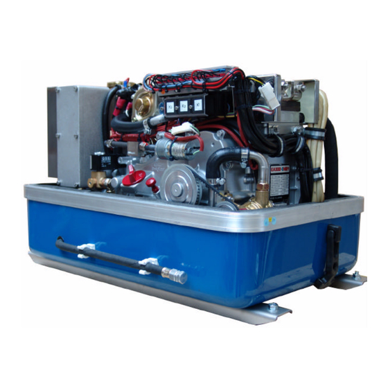
- Page 1 Installation manual Installation, maintenance and troubleshooting Marine Generator Panda AGT-DC 4000 PMS 12V - 24V / 4kW Icemaster Fischer Panda...
- Page 2 Icemaster GmbH Panda generators Generators Fischer Panda FISCHER GENERATORS have been manufactured since 1978 and are a well-known brand for first class diesel gene- rators with especially effective sound-insulation. Fischer has been one of the leading manufacturers in respect of quality and know-how during this period.
- Page 3 Upgrades Far advantages: By your full information Fischer Panda technicians can give you fast assistance, since 90% of the disturbances result from errors in the periphery. Problems due to errors in the installation can be recognized in the apron.
- Page 4 Safety Instructions The electrical Installations may only be carried out be trained and tested personnel! The generator may not be taken into use with the cover removed. The rotating parts (belt-pulley, belts, etc) must be so covered and protected do that there is no danger to life and body! If a sound insulation covering must be produced at the place of installation, then well-placed signs must show that the generator can only be switched on with a closed capsule.
- Page 5 CAUTION! The AGT-generator is not allowed to be connected to an inverter (without batteries)! The Inverter generates voltage peaks, which can destroy the rectifier diodes of the generator! A battery must always be connected to the inverter as a capacity! ≥...
- Page 6 Measures to the fire protection. All construction units in the environment of energized parts, which carry more than 50 Amp., must be fire protection- moderately secured. All junction points at the energized parts must be examined regularly on heating up (infrared thermometers). Safety Instrictions for the Handling with Batteries These instructions must be noticed additionally to the instructions of the battery manufacturer: •...
-
Page 7: Table Of Contents
Table of Contents Mode of Operation of the Generator ................5 A.1 Mode of Operation of Operating Surveillance ..............5 A.1.1 Regulation of the generator voltage by the VCS ............... 7 A.1.2 Overloading of engine during longer operation ................. 8 A.2 Operation of the generator with HTG generator ..............8 A.2.1 Allgemeine Hinweise ......................... - Page 8 C.5.2 De-aerating the fuel system....................36 C.6 Troubleshooting Table ......................37 C.5.3 Fuel Solenoid Valve........................ 37 Installation Instructions ....................39 D.1 Placement ..........................39 D.1.1 Placement and Basemount ....................39 D.1.2 Notice for optimal sound insulation..................39 D.2 Generator Connections - Scheme ..................40 D.2.1 Connections Panda AGT 4000 12V ..................
- Page 9 Types of coil ........................VIII Inspection checklist for services ..................IX Engine oil ..........................X Coolant specifications ......................XI Measurements ........................XII Panda PMS AGT-DC 4000 - Table of Contents - Page 3...
- Page 10 Page 4 Panda PMS AGT-DC 4000 - Table of Contents...
-
Page 11: Mode Of Operation Of The Generator
Mode of Operation of the Generator A. Mode of Operation of the Generator A.1 Mode of Operation of Operating Surveillance Internal monitoring switches The generator is equipped about failure switches, which are indicated on the remote control panel, and also about failure switch, which switch-off the generator automatically without indica- ting a failure in the remote control panel: The remote control panel supervised the following values. - Page 12 Mode of Operation of the Generator Thermo-switch exhaust connection If the impeller pump should fail, the raw water stream fed here tears off and the exhaust connection heats up immediately extremely fast, since the water cooling is missing. The thermo-switch supervises a functioning raw water cycle.
-
Page 13: Regulation Of The Generator Voltage By The Vcs
Mode of Operation of the Generator Coikl thermo-switch 1. Thermo-switch coil 125°C 2. Generator housing 3. Thermo-sensor NTC 981S (for measuring) Fig. A.5: Thermo-switch coil Oil pressure switch at diesel engine The combustion engine is equipped with an oil pressure control switch, which swit- ches the engine off if the oil pressure drops under a certain value. -
Page 14: Overloading Of Engine During Longer Operation
Mode of Operation of the Generator A.1.2 Overloading of engine during longer operation Please ensure that the genset is not overloaded. Overloading occurs when the electrical load (demand) induces a load torque in the generator which is higher than that which the diesel drive motor can provide. -
Page 15: Betrieb Des Generators Bei Einbau Unter Der Wasserlinie
Mode of Operation of the Generator A.4 Betrieb des Generators bei Einbau unter der Wasserlinie If the generator cannot be installed clearly at least 600mm over the waterline, a vent valve must be installed into the raw water line. At installation beside the "midship´s line" a possible heeling must be considered! The water hose in the sound cover is split on the heat exchanger outlet and extended in each case in the sound cover at both ends with a connecting nipple by a hose end. -
Page 16: Control Of The Vent Valve
Mode of Operation of the Generator A.4.1 Control of the vent valve If the valve is blocked, the cooling water pipe cannot be ventilated after the stop of the generator, the water column is not interrupted and the water can penetrate into the combustion chamber of the engine. -
Page 17: Maintenance Instructions
Maintenance Instructions B. Maintenance Instructions B.1 General maintenance instructions B.1.1 Checks before starting • Oil level • Cooling system leaks • Visual check for any changes, leaks oil drain system, v-belt, cable connections, hose clips, air filter, fuel lines Once a month •... -
Page 18: Execution Of An Oil Change
Maintenance Instructions B.3 Execution of an oil change Oil drain hose For the oil change an oil drain hose is lead through the sound cover. Oil drain screw The oil can be discharged by opening the oil drain screw. For countering use a second wrench. - Page 19 Maintenance Instructions Oil strainer The oil strainer must be cleaned every 500 opeatiing hours. Open the oil filler neck After opening the cap of the oil filler neck the new oil is refilled. Please wait instant, before measure the oil level, the oil must set off in the sump.
-
Page 20: Checking The Water Separator In The Fuel Supply
Maintenance Instructions B.4 Checking the water separator in the fuel supply The pre-filter with water separator has a cock at its lower surface, with this cock the downward sunk water can be discharged. This is simply possible, water is heavier due to its density than the Diesel. - Page 21 Maintenance Instructions 2. Take off the plug at the solenoid of the starter motor. 3. Switch the panel „ON“. 4. Press „START“-button. The fuel pump runs audible. 5. Switch the panel „OFF“. 6. Switch the panel „ON“. 7. Press again the „START“-button. T h i s p r o c e d u r e m u s t b e r e p e a t e d several times, until fuel (nonporously) withdraws perfectly at the fuel return...
-
Page 22: Exchange The Air Filter
Maintenance Instructions B.4.2 Exchange the air filter Open the air suctin housing by loosen the six hexagon head screws on the frame cover. Change the air filter mat and close the cover again. Page 16 Panda PMS AGT-DC 4000 - Chapter B: Maintenance Instructions... -
Page 23: Aerating Of The Coolant Circuit / Freshwater
Maintenance Instructions B.5 De-aerating of the coolant circuit / freshwater Special notes for the ventilation of the cooling system If the cooling water is drained or if other air should have arrived into the cooling system, it is necessary to de-aerate the cooling system. This de-aerate procedure must be repeated several times: ATTENTION ! Before opening the de-aerating points the generator must be stagnant !!! Open the ventilation valve over the coo-... -
Page 24: Exchange Of The Toothed Belt For The Raw Water Pump
Maintenance Instructions Exchange of the toothed belt for the raw water pump The relative high ambient temperature in the closed sound insulated capsule (about 85°C) can be a reason for a reduced lifespan of the toothed belts. It is possible that the "softener" in the rubber compound lose their effect after a short operating time because the air in the sound insulated capsule can be relative warm and dry. -
Page 25: The Raw Water Circuit
Maintenance Instructions Screw on the raw water pump again. Fasten the fixing bolts to the raw water pump again. B.7 The raw water circuit B.7.1 Clean raw water filter The raw water filter should be released regularly from arrears. In each case the water cock must be closed before. -
Page 26: Causes With Frequent Impeller Waste
Maintenance Instructions B.7.2 Causes with frequent impeller waste The impeller of the cooling water pump must be regarded as wearing part. The life span of the impeller can be extremely different and exclusively depends on the operating conditions. The cooling water pumps of the PANDA generators are laid out in such a way that the number of revo- lutions of the pump lies low compared with other aggregates. - Page 27 Maintenance Instructions Raw water pump on the front side of the genset. Remove the cover of the raw water pump by loosen the wing screws from the hou- sing. Pull to the impeller with a multigrip pliers of the wave. Mark the impeller, to make sure that these is used in the correct position at re-instal- lation.
- Page 28 Maintenance Instructions Check to the impeller for damage and replace it if necessary. Before the reinsertion into the housing the impeller should have been lubricated with glycerin or with a non-mineral oil based lubricant e.g. silicone spray. The impeller is attached to the pump wave (if the old impeller is used, pay attention to the before attached marking).
-
Page 29: Additional Maintenance
Maintenance Instructions B.8 Additional maintenance Furthermore in addition to the standards checks according to the manual following points of the generator have to be checked: • automatic shut down of the generator in case off high heating temperature This shall be done by disconnecting the thermo-switch of the heat sink. Next to the rectifier you will find a 2-pole connector. - Page 30 Maintenance Instructions Ensure, that a fuse next to the battery is installed in the battery line for the generator output cable. Ensure that a battery switch is installed in the battery line. Never leave the generator behind wit- hout the cover mounted over the heat sink and capsule not closed. Sicherung Fuse Batterie-Trennschalter...
-
Page 31: Conservation At Longer Operation Interruption
Maintenance Instructions B.9 Conservation at longer operation interruption B.9.1 Measures on preparation of the winter storage 1. Rinse raw water circuit with an anti-freeze solution, even if this contains a corrosion protection means. The raw water inlet must be removed at the water cock. Over a hose connector the anti-freeze protection mixture is to be sucked in from a container. -
Page 32: Initiation At Spring
Maintenance Instructions B.9.1 Measures on preparation of the winter storage 13.The generator housing and the housing of the engine should be sprayed with a corrosion pro- tection oil before the winter storage. This procedure is recommended also in the season. This procedure can avoid that arising and humidity marks on the surface of the aluminum construc- tion units be noticed too late. -
Page 33: Generator Failure
Generator Failure C. Generator Failure C.1 Tools and measuring instruments In order to be able to manage disturbances while driving, following tools and measuring instruments should belong to the equipment on board: • Multimeter for voltage (AC), frequency and resistance •... -
Page 34: Adjusting The Nominal Charge Current
Generator Failure C.3 Adjusting the nominal charge current ATTENTION! Before working on the System read the section “Safety Instructions” on Page iv. These adjustments may not be changed, they are sealed. The adjustments should be changed expires the warranty. The adjustments of the nominal charging current is made at the actuator. By the nuts on the left and on the right at the spindle of the actuator the adjustment is limited. -
Page 35: Effects Of A Overload To The Actuator
Generator Failure 01. Actuator 02. Spiral thread spindle C.3.2 Effects of a overload to the actuator If the generator is overloaded the voltage falls on account of a not adequate motor power under the nominal value. The actuator stays at the upper keystroke and tries to rev up the diesel engine. An internal regulation limits the current to the actuator, nevertheless a longer overload can damage the winding of the actuator. - Page 36 Generator Failure Possible disturbances in the area of the rev regulation "VCS" Failure Cause The spindle of the actuator jams • not regularly lubricated. • surface is mechanical damaged. • actuator is defect. • defect of the VCS control (short of winding). •...
-
Page 37: Low Generator-Output Voltage
Generator Failure Change the VCS printed circiut board if the points above carries no clearance. Überprüfen der Begrenzung der Generatorspannung The mechanical voltage limitation must be checked regularly. The following steps have to be done: 1. Disconnect the plug of the actuator. Lower suspension point: 2. -
Page 38: Testing Generator Stator Windings
Generator Failure C.4 Testing Generator Stator Windings ATTENTION! Before working on the System read the section “Safety Instructions” on Page iv. C.4.1 Testing Generator Stator Winding for "Shorts" to Ground The generator stator windings can be tested as follows: 1. Ensure that the generator is "OFF" and cannot be accidentally started. Disconnect the battery. 2. -
Page 39: Coil Resistance Measurements In Stator Windings
Resistance measure between different windings. If the value is in the Giga ohm area, the coil is correct. If you find any anormality, when doing this test, please ask your Fischer Panda dealer. If strong deviations are measured in the individual coil windings, there is a coil short-cut in one coil. -
Page 40: Measuring The Coil Inductive Resistance
Generator Failure C.4.3 Measuring the Coil Inductive Resistance Unfortunately the checking of the ohmic resistance permits still no reliable statement about the condition of the coil. If the ohmic resistance values arise inequalities between the coils, that is a safe indication for the fact that the coil is defective. To be exactly sure the inductive resistance of the coil have to be measured. -
Page 41: Starting Problems
Generator Failure C.5 Starting Problems C.5.1 VCS does not work For start problems one chief cause is that the VCS doen not work. Check: Is the voltage sense connecttion ok? Check polatrity! Is the shunt connection ok? Check pola- trity! Is the main supply connection ok? Check polatrity! Does DP+ (VCS ON) lie on clamp 6 of the... -
Page 42: Aerating The Fuel System
Generator Failure Checking the fuse on the VCS printed cir- cuit board. C.5.2 De-aerating the fuel system Normally, the fuel system is designed to bleed out air itself i.e. as soon as the electric starter motor starts operation the fuel pump starts working and the fuel system will be de-aerated after some time automatically. -
Page 43: Troubleshooting Table
Generator Failure C.5.3 Fuel Solenoid Valve For start problems the possibility of an error exists with the solenoid for engine stop or fuel sole- noid valve, which both effect affect simultaneous on the fuel system. The fuel solenoid valve is located in front of the injection pump. It opens automatically, if the "START"-button is pressed on the remote control panel. - Page 44 Generator Failure Page 38 Panda PMS AGT-DC 4000 - Chapter C: Generator Failure...
-
Page 45: Installation Instructions
Installation Instructions D. Installation Instructions D.1 Placement D.1.1 Placement and Basemount Since Panda generators have extremely compact dimensions they can be installed in tight locati- ons, attempts are sometimes made to install them in almost inaccessible places. Please consider that even almost maintenance-free machinery must still remain accessible at least at the front (drive belt, water pump) and the service-side (actuator, dipstick). -
Page 46: Generator Connections - Scheme
Installation Instructions D.2 Generator Connections - Scheme The generator comes supplied with all supply lines (i.e. electric cables, fuel lines etc.) already connected to the motor and generator. The supply lines are fed through the capsule's front base panel and are shielded at the capsule inlets with water-proof grommets. All electrical connections, cable types and sizes must comply to the appropriate regulati- ons. -
Page 47: Connections Panda Agt 4000 24V
Installation Instructions D.2.2 Connections Panda AGT 4000 24V ATTENTION! Before working on the System read the section “Safety Instructions” on Page iv. Passage for battery cable Cable for voltage sense Passage for battery cable Cable for shunt Raw water inltake Connection fuel IN Cable for remote control panel 10. -
Page 48: Cooling System Installation - Raw Water
Installation Instructions D.3 Cooling System Installation - Raw water D.3.1 General References The genset should have its own raw water (coolant water) inlet and should not be connected to any other engine systems. Ensure that the following installation instructions are complied with: Avoid galvanic corrosion For the avoidance of galvanic corrosion the chapter "Service instruction for marine aggre- gates (corrosion protection)“... -
Page 49: Installation Above Waterline
Installation Instructions D.3.4 Installation above waterline The Panda is equipped with a direct drive water intake pump mounted directly on the motor. Since the intake pump is an impeller pump there are wearing parts which will likely require repla- cement after some time. Ensure that the genset is installed such that the intake pump can be easily accessed. -
Page 50: Installation Below Waterline
Installation Instructions D.3.5 Installation below waterline If the generator can not be attached at least 600mm over the waterline, a vent valve must be installed into the seawater line. With location beside the "midship line" a possible hee- ling must be considered! The water hose for the external vent valve at the back of the sound cover splits on the pres- sure side of the pump and at both ends in each case exten- ded with a connecting nipple by a hose end. -
Page 51: The Freshwater - Coolant Circuit
Installation Instructions D.4 The Freshwater - Coolant Circuit D.4.1 De-aerating at the first filling of the internal cooling water circuit 1. For the preparation of filling the following steps are to be undertaken: a. Open the cooling water cap on the coo- ling water tank. - Page 52 Installation Instructions Anti-freeze In the interest of safety, the freezing point of the closed circuit coolant should be checked on a regular basis. Be sure that the coolant/antifreeze mixture is good for at least -15°C (5°F) and if it is possible that your genset experiences lower temperatures, for example during storage or trans- portation, then the entire cooling system should be drained and purged.
-
Page 53: Pressure Test For Control Of Cooling Water Circuit
Installation Instructions D.4.2 Pressure test for control of cooling water circuit Check with the hand if a temperature difference exists whether between cooling water in-flow and cooling water return. Feel the cooling water in-flow line at the internal cooling water pump. Feel the cooling water return pipe either at the outlet of the water-cooled exhaust elbow union or at the side, where this pipe entry at the heat exchanger. -
Page 54: Watercooled Exhaust System
Installation Instructions D.5 Watercooled Exhaust System By injecting the outlet raw water into the exhaust manifold, the exhaust gases are cooled and the noise emissions from the exhaust system are reduced. D.5.1 Installation of the standard exhaust system The generator exhaust system must remain completely independent and separate from the exhaust system of any other unit(s) on board. -
Page 55: Exhaust / Water Separator
Installation Instructions D.5.2 Exhaust / water separator The exhaust/water separator In order to reduce the noise level of the generator unit to a minimum, an optional exhaust outlet muffler mounted next to the thru-hull fitting can be installed. Additionally there is component at ICEMASTER, which exercise both functions of a "exhaust goose neck", and the water separation. -
Page 56: Installation Exhaust/Water Separator
Installation Instructions D.5.3 Installation exhaust/water separator If the exhaust/water separator was sufficiently highly installed, a goose neck is no longer neces- sary. The exhaust/water separator fulfills the same function. If the "Supersilent" exhaust system were installed correctly, the generator will not disturb your boat neighbour. The exhaust noise should be nearly inaudible. - Page 57 Installation Instructions Example of an unfavorable installation: - water lock not deeply enough under the hights level of the generator - distance water lock to exhaust/water separator too largely Panda PMS AGT-DC 4000 - Chapter D: Installation Instructions Page 51...
-
Page 58: Fuel System Installation
Installation Instructions D.6 Fuel System Installation D.6.1 General References Additional fuel filters (with water seperator) must be mounted outside the capsule in easily acces- sible places in the fuel lines between the tank intake fuel pump and the diesel motor's fuel pump. Generally forward and return fuel flow pipes must be mounted to the diesel tanks. -
Page 59: The Electrical Fuel Pump
Installation Instructions D.6.2 The electrical fuel pump Electrical fuel pump With the Panda generator is usually supp- lied an external, electrical fuel pump (12V DC). The fuel pump must be installed close at the fuel tank. The electrical con- nections are preloaded at the generator with the lead planned. -
Page 60: Position Of The Pre-Filter With Water Separator
Installation Instructions D.6.4 Position of the pre-filter with water separator Additionally to the standard fine filter a pre- filter with water separator must be installed outside of the sound cover in the fuel system line. (is not included in delivery.) D.7 Generator DC System-Installation D.7.1 Connection of the 12V starter battery (only for 24V version) The positive (+) battery cable is connected... -
Page 61: Terminal Block Agt 4000 12V
Installation Instructions D.7.2 Terminal block AGT 4000 12V The Panda generators are equipped with various DC-relays, which can be found under the terminal strip. The various relays have the following tasks (also see the DC circuit diagram) F1: Fuse 15A for DC-system F2: Fuse 10A for AC-system K1: Starter motor relay K2: Pre-glow relay (glow plug) -
Page 62: Installation Of The Remote Control Panel
Installation Instructions D.7.4 Installation of the remote control panel As standard a 12 core connection-cable, 7m long, is included in the supply. Cores are numbered from 1 to 11 and the 12th core is coloured (yellow/green). The con- trol cables are securely connected to the genset. - Page 63 Installation Instructions 1. Display operating hours 2. Control light - temperature 3. Control light - oil pressure 4. Control light - charge control 5. Control light - operating status red glowing Generator is in „Stand-by“-mode red blinking Generator is started manually red blinking for more than 20 seconds Generator did not start when activated manu- ally...
- Page 64 Installation Instructions 8. Main terminal clamp - allocation: 1: Battery plus (+) 2: Battery minus (-) 3: Input temperature failure 4: Input charge control 5: Input oil pressure failure 6: Input generator voltage 1 7: Input generator voltage 2 8: Output pre-glow 9: Output fuel pump 10: Output starter motor 11: Output VCS-ON (voltage control for VCS)
- Page 65 Installation Instructions 10.Terminal clamp for external automatic start - allocation: 15: Battery minus (-) 16: Input for external start demand The potential-free contact can be connected to these two terminal. The starting sequence occurs automatically if the contact closes. 11.Fuse 1,6A slow to blow 12.Switch for the starter motor cut-off voltage: Switch 1: 12V - generator Switch 2: 24V - generator...
- Page 66 Installation Instructions Discription of the illuminate diode (5) LED all LED´s off Generator is off red LED illuminates constant Generator is in „Stand-by“-mode red LED blinks up to 20s Generator is in start mode red LED blinks more than 20s Generator had not been started -->...
-
Page 67: The Speed Sensor
Installation Instructions D.7.6 The speed sensor Plug for speed sensor Installation of the speed sensor The speed sensor tip must have between 0.3 to 0.8mm of clearance (air gap) from the gear rim tips. In order to achieve this clearance: the speed sensor tip should be aligned with the tip of a gear rim and screwed in until it touches the tip of the tooth. -
Page 68: Generator Dc System-Installation
Installation Instructions D.8 Generator DC System-Installation ATTENTION! Before the electrical system is installed, READ the “Safety Instructions” on Page iv of this manual FIRST! Be sure that all electrical installations (including all safety systems) comply with all required regulations of the regional authorities. This includes lightnening conductor, personal protection switch etc. -
Page 69: Installation Panda Agt 24V-System
Installation Instructions D.8.2 Installation Panda AGT 24V-system 1. Generator 6. Voltage control VCS 2. Battery bank 24V 7. Starter battery 12V 3. Battery monitor 8. Fuse 4. Fuel pump 9. Battery switch 5. Remote control panel All electrical safety installations have to be made on board. Panda PMS AGT-DC 4000 - Chapter D: Installation Instructions Page 63... - Page 70 Installation Instructions Electrical fuses It is absolutely essential that the electrical system installation is inspected by a qualified electrical technician. The generator should have its own AC input electrical fuses. The fuses should be sized such that the rated current of the generator on each of the individual phases is not excee- ded by more than 25%.
-
Page 71: Voltage Control System
Installation Instructions D.9 Voltage Control System The VCS control is used for the adjustment of the number of revolutions of the engine and thus the voltage of the generator. It belongs to the accessories and is externally attached. VCS 12V 01. - Page 72 Installation Instructions VCS 24V 01. Voltage sense (+) (24V) 06. Battery voltage supply (-) 02. Voltage sense (-) (24V) 07. Stop line (regulates the actuator back at shut-off 03. Actuator (+) the device) 04. Actuator (-) 08. Terminal shunt measurement 0mV DC (-) 05.
-
Page 73: Voltage Controller
Installation Instructions D.10 Voltage controller With a engine-operated generator set count always on the fact that through disturbances at the controlling of the diesel engine the control of the number of revolutions monitoring is lost. In this case the diesel engine could wind up without limitation and produce a voltage, which becomes substantially larger than the electrical load can process. -
Page 74: Time Lag Of The Switching Points
Installation Instructions A) upper switching point (shut-down) B) lower switching point (starting) C) td = time lag of the generators after rea- ching the upper switching point 1. Voltage sense plus (+) 2. Voltage sense minus (-) 3. Charging voltage 4. - Page 75 Tables F. Tables Tabelle 1: Diameter of conduits Ø Cooling water pipe Ø Fuel hose Ø Exhaust hose Fresh water Raw water Supply Return Generator type [mm] [mm] [mm] [mm] [mm] Panda PMS AGT 4000 Tabelle 2: Technical Data Continuous Nominal Nominal power Continuous...
- Page 76 Tables Tabelle 3: Cable cross-section Wiring for vehicle. single phase, not tin-plated, PVC-isolated. allowed conrinuous current (reference point) nominal wire cross-section [mm²] at +30°C [A] at +50°C [A] 13,5 17,0 22,7 29,8 38,3 51,8 69,6 91,6 a. DIN VDE 0298, part 4. Page II Panda PMS AGT-DC 4000 - Chapter F: Tables...
-
Page 77: Trouble Shooting
Tables F.1 Trouble shooting GENERATOR OUTPUT VOLTAGE TOO LOW If the generator delivers less than 24V current ("undervoltage"), there can be various reasons for this: Cause Solution Generator is overloaded. Reduce the electrical load. (Switch off load) Motor is not reaching the rated rpm. Refer to "motor faults"... - Page 78 Tables MOTOR TURNS OVER BUT DOES NOT START Cause Solution Stop solenoid valve not opening. Check wire connections and circuitry to solenoid valve. (ref. DC wiring diagram: Relay K2, Fuse) Fuel pump does not operate. Check fuel-filter and pump: clean if necessary. Lack of fuel.
- Page 79 Tables DROP IN THE SPEED OF THE MOTOR Cause Solution Too much oil. Drain oil. Lack of fuel. Check fuel supply system: - fuel filter, renew if necessary - check fuel pump - check fuel lines (bleed if necessary) Lack of intake air. Check air intake paths.
- Page 80 Tables SOOTY, BLACK EXHAUST Cause Solution Generator is overloaded. Check electrical load and switch off unnecessary load. Insufficient intake air. Check intake air filter; clean if necessary. Fuel injector nozzles faulty. Replace injector nozzles. Valve clearance incorrect. Readjust valve clearance to correct value (refer to Kubota-manual).
-
Page 81: Technical Data Engine
Tables F.2 Technical Data Engine Panda AGT-DC 4000 PMS Type EA 300 Govenour Cylinder Bore 75mm Stroke 70mm Stroke volume 309cm max. Power (DIN 6270-NB) at 3000rpm 5,1kW Rated speed 50 Hz 3000rpm 2900rpm Idle speed running Valve clearance (engine cold) -
Page 82: Types Of Coil
Tables F.3 Types of coil HP3 delta connection HP3 star connection Page VIII Panda PMS AGT-DC 4000 - Chapter F: Tables... -
Page 83: Inspection Checklist For Services
Tables F.4 Inspection checklist for services Inspection-Category Inspection work 100 h check change Installation check 500 h measure sealing daily 1000 h clean check isolation 35 - 50 h 5000 h Inspection-Category Inspection work coolant water hoses raw water pump (impeller) water separator / fuel pre-filter engine oil oil strainer... -
Page 84: Engine Oil
Tables F.5 Engine oil Engine oil classification Operating range: The operating range of an engine oil is determined by SAE class. "SAE" is for the union of American engineers (Society of Automotives Engineers). The SAE class of an engine oil only informs over the viscosity of the oil (lar- ger number = more viscous, lower number = more highly liquidly) e.g. -
Page 85: Coolant Specifications
Tables F.6 Coolant specifications Use a mixture of water and antifreeze. The antifreeze needs to be suitable for aluminium. The antifreeze concen- tration must be regularly checked in the interests of safety. ICEMASTER recommend to use the product: GLYSANTIN PROTECT PLUS/G 48. Engine coolant automotive industry Product description Product name GLYSANTIN ®... -
Page 86: Measurements
Tables F.7 Measurements Page XII Panda PMS AGT-DC 4000 - Chapter F: Tables... - Page 87 5 Safety steps to follow if someone is the victim of electrical shock Do not try to pull or grab the individual. If you cannot turn off the electrical power, pull, push, or lift the person to safety using a wooden pole, rope, or some nonconductive material.
- Page 88 WHEN AN ADULT STOPS BREATHING WARNING DO NOT attempt to perform the rescue breathing techniques provided on this page, unless certified. Perfor- mance of these techniques by uncertified personnel could result in further injury or death to the victim. Does the Person Respond? Shout, "Help!"...
Need help?
Do you have a question about the AGT-DC 4000 PMS and is the answer not in the manual?
Questions and answers