
Related Manuals for Fischer Panda Panda PMS-HD 12-4KU


Summary of Contents for Fischer Panda Panda PMS-HD 12-4KU
- Page 1 Manual Description of the generator and operation manual Marine Generator Panda PMS-HD 12-4KU Super silent technology 230V/400V - 50Hz / 10,5kW 120V/240V - 60Hz / 10,5kW Fischer Panda GmbH...
-
Page 2: Current Revison Status
Duplication and change of the manual is permitted only in consultation with the manufacturer! Fischer Panda GmbH, 33104 Paderborn, reserves all rights regarding text and graphics. Details are given to the best of our knowledge. No liability is accepted for correctness. Technical modifications for impro- ving the product without previous notice may be undertaken without notice. -
Page 3: Table Of Contents
Table of contents Current revison status ......................2 5 Safety steps to follow if someone is the victim of electrical shock ....... 7 WHEN AN ADULT STOPS BREATHING................8 Safety first ..........................10 Tools ............................11 Safety Precautions ....................... 13 The Panda Generator.................... - Page 4 Table of contents B.4.6 Measuring the Inductive Resistance .................. 54 B.5 Generator provides no voltage ..................55 B.5.1 Rotor Magnetism Loss and "Re-magnetising" ..............55 B.6 Engine Starting Problems ....................55 B.6.1 Fuel Solenoid Valve ......................55 B.6.2 Re-start with Failure Bypass Switch .................. 56 B.6.3 Troubleshooting Table .......................
- Page 5 Table of contents D.5.2 Exhaust / Water separator ....................90 D.5.3 Installation Exhaust-Water-Separator ................91 D.6 Installation of the Fuel System ..................92 D.6.1 General References ......................92 D.6.2 The Electrical Fuel Pump ....................93 D.6.3 Connection of the Fuel Lines at the Tank ................94 D.6.4 Position of the Pre-Filter with Water Separator ..............
- Page 6 Table of contents A.7.1 Terminal connections ....................... 142 A.7.2 Configuration and adjustment ..................143 Measurements ......................147 B.1 Hole pattern ........................147 Page 6 Panda_12-4KU_HD-PMS_eng.R02 - Table of contents 8.7.08...
-
Page 7: Safety Steps To Follow If Someone Is The Victim Of Electrical Shock
5 Safety steps to follow if someone is the victim of electrical shock Do not try to pull or grab the individual. Send for help as soon as possible. If possible, turn off the electrical power. If you cannot turn off the electrical power, pull, push, or lift the person to safety using a wooden pole, rope, or some nonconductive material. -
Page 8: When An Adult Stops Breathing
WHEN AN ADULT STOPS BREATHING WARNING DO NOT attempt to perform the rescue breathing techniques provided on this page, unless certified. Performance of these techniques by uncertified personnel could result in further injury or death to the victim. Does the Person Respond? Shout, "Help!"... - Page 9 Fischer Panda GmbH, 33104 Paderborn, reserves all rights regarding text and graphics. Details are given to the best of our knowledge. No liability is accepted for correct- ness. Technical modifications for improving the product without previous notice may be undertaken without notice. Before installation, it must be ensured that the pictures,...
-
Page 10: Safety First
Safety first These symbols are used throughout this manual and on labels on the machine itself to warn of the possibility of per- sonal injury. Read these instructions carefully. It is essential that you read the instructions and safety regulations before you attempt to assemble or use unit. -
Page 11: Tools
Tools This symbols are used throughout this manual to show which tool must be used at maintenance or installation. Spanners X = required size Hook wrench for oil filter Screw driver, for slotted head screws and for recessed head screws Multimeter, multimeter with capacitor measuring Socket wrench set Hexagon wrench keys... - Page 12 2. The installation certificate must be despatched within two weeks of use to Fischer Panda. 3. The official guaranty confirmation will be completed by Fischer Panda after receipt and sent to the customer. 4. A guaranty must be shown to make any claims.
-
Page 13: Safety Precautions
Safety Precautions The electrical installations may only be carried out by trained and qualified personnel! Safety Instructions concerning operating the generator • The generator must not be taken into use with the cover removed. • If the generator is being installed without a sound insulation capsule, then make sure, that all rotating parts (belt- pulley, belts etc) are covered and protected so that there is no danger to life and body! •... - Page 14 Safety Instructions concerning the capacitors Capacitors are required to run the generator. These have two varying functions: A) The working capacitors B) The (Booster) capacitors Both Groups are located in a separate AC-Control box. Capacitors are electrical stores. There could be a residual of high electrical current at the contacts for a period dis- connection from the circuit.
-
Page 15: The Panda Generator
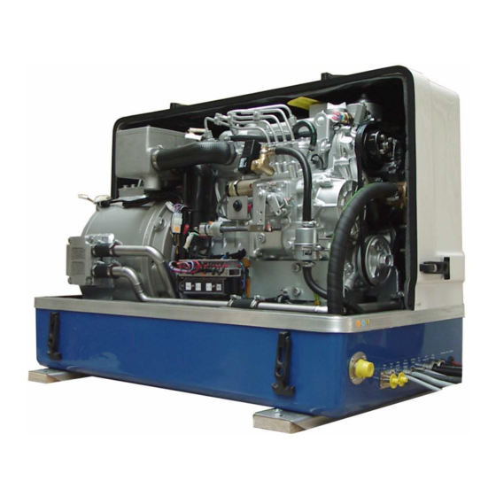
The Panda Generator A. The Panda Generator A.1 Type plate at the Generator Fig. A.1-1: Type plate Fig. A.1-2: Discription type plate... -
Page 16: Right Side View
The Panda Generator A.2 Description of the Generator A.2.1 Right Side View 01. Thermostat housing 11. Cooling water filler neck with cap 02. 12V-DC-alternator 12. Water-cooled exhaust elbow 03. V-belt for DC-alternator and cooling water pump 13. Starter motor 04. Raw water pump 14. -
Page 17: Left Side View
The Panda Generator A.2.2 Left Side View 13 14 17 18 19 01. Generator housing with coil 13. Cooling water pipe, connection block - water pump 02. Air suction housing with air filter 14. Plug for speed sensor 03. Suction hose, air suction housing - induction elbow 15. -
Page 18: Front View
The Panda Generator A.2.3 Front View 07 08 01. Ventilation screw water pump 13. Electrical cable for AC-Control box 02. Thermo-switch at thermostat housing 14. Electrical cable for load 03. Fuel solenoid valve 15. Starter battery minus (-) 04. Hose for raw water intake 16. -
Page 19: Back View
The Panda Generator A.2.4 Back View 02 03 01. Power terminal box 06. Thermo-switch at oil cooled bearing 02. Intake from the external cooling water expansion tank 07. Cooling water connection block 03. Backflow to the external cooling water expansion tank 08. -
Page 20: View From Above
The Panda Generator A.2.5 View from above 01. Generator housing with coil 09. 12V DC-alternator 02. Power terminal box 10. Ventilation screw thermostat housing 03. Air suction housing with air filter 11. Suction hose, air suction housing - induction elbow 04. -
Page 21: Details Of Functional Units
The Panda Generator A.3 Details of functional units A.3.1 Remote control panel - see remote control panel datasheet The remote control panel is necessary to control the generator and to evaluate the motor/genera- tor properties. The generators will automatically cutout if it does not run as required. The genera- tor may not be run without the remote control panel. - Page 22 The Panda Generator Heat exchanger Separates the raw water system from the freshwater system. Fig. A.3.3-2: Heat exchanger Ventilation valve A siphon must be installed if the generator sinks below the water line because of the rocking of the boat, even if it is only for a short period of time.
-
Page 23: Components Of Cooling System (Freshwater)
The Panda Generator A.3.4 Components of Cooling System (Freshwater) Cooling water filler neck The cooling water filler nck situated at the water-cooled manifold are only used, when the generator is initially started. Since the generator is normally already fil- led with cooling water, these components are only by the user, if repairs are to be carried out. - Page 24 The Panda Generator Freshwater backflow The cooling water is fed to the heat exchanger from the water-cooled manifold by means of the pipe shown in the dia- gram. Fig. A.3.4-4: Freshwater backflow Heat exchanger Separates the raw water system from the freshwater system.
- Page 25 The Panda Generator Internal cooling water pump The diesel motor cooling water pump (see arrow) aids the circulation of the internal freshwater system. Fig. A.3.4-7: Internal cooling water pump Cooling water intake The intake pipe from the external cooling water expansion tank is connected here. Fig.
-
Page 26: Components Of The Fuel System
The Panda Generator Ventilation screw thermostat housing The ventilation screw on the thermostat housing should occasionally be opened for control purposes. Standing machinery should principally carry out ventilating. Fig. A.3.4-10: Ventilation screw thermostat housing Water-cooled exhaust manifold The manifold is cooled by means of the internal cooling system (freshwater). - Page 27 The Panda Generator Connecting pieces for the fuel pipe 1. Fuel intake 2. Fuel backflow Fig. A.3.5-2: Fuel connections Fuel Filter A consequential filtering of fuel is espe- cially important for all marine systems. A fine filter, which is firmly attached to the inside of the sound insulation cap- sule for the marine version, is supplied on delivery, and loose for other makes.
- Page 28 The Panda Generator Fuel solenoid valve The fuel solenoid valve opens automati- cally if „START“ is pressed on the remote control panel“. The solenoid closes, if the generator is switched to „OFF“ position. It takes a few seconds before the generator stops.
-
Page 29: Components Of Combustion Air
The Panda Generator Stop solenoid for engine stop Some model are additional equipped with an stop solenoid. The generator is stopped by the co-operation of the stop solenoid immediately after switching off. The adjust- ment of the stop solenoid must always be checked, in order to be sure that the stop lever can move also during the operation freely and is not under pre-stressing. - Page 30 The Panda Generator Air suction housing with air filter set The figure shows the air filter element in the air suction housing. However the return pipe of the crank case exhaust flows also into the air suction housing, it can be faced with older generators and/or with engines on high running time that oel vapors affect the air filter.
-
Page 31: Components Of The Electrical System
The Panda Generator Exhaust connection at the exhaust elbow Raw water from the external cooling circle is fed here. Fig. A.3.6-6: Exhaust connection Exhaust outlet Connect the exhaust pipe with the water lock. Fig. A.3.6-7: Exhaust outlet A.3.7 Components of the electrical system Connection starter battery 1. - Page 32 The Panda Generator Electrical connection for control At the front of the generator also all remai- ning cables for the electrical connections are depending upon type. The allocation of the connections result from the plan for the AC-Control box. See here: 1.
- Page 33 The Panda Generator Actuator for speed regulation The generator voltage is determined by progressive speed control through "VCS" in conjunction with the speed actuator. Speed increases with increasing load. Fig. A.3.7-5: Actuator Blind plug for speed sensor All Panda generators can be equipped with an external automatic start.
- Page 34 The Panda Generator Generator Power Terminal Box 230V/50Hz To locate the Terminalbox see Chapter A2. In these terminal boxe there are the elec- trical connection points for the AC genera- tor. Here is also the bridge for the protective grounding of the generator. The cover may only be removed, if it is guaran- teed that the generator cannot be inadver- tently started.
-
Page 35: Sensors And Switches For Operating Surveillance
The Panda Generator Terminal block for fuses and power relay F1 fuse 15A for DC-wiring F2 fuse 25A for starter motor K3 K4 Ks power relay for starter motor K2 power relay for glow plugs K3 power relay for fuel pump K4 power relay for stop solenoid F1 F2 Fig. - Page 36 The Panda Generator Thermo-switch at exhaust connection If the impeller pump drop out and deliveres no more raw water, the exhaust connection becomes extremely hot. 98/83° C Fig. A.3.8-3: Thermo-switch at exhaust connection Thermo-switch at the endshield The generator bearing is equipped with an oil thermoswitch, which switches the engine off if the oil temperature becomes to high.
-
Page 37: Components Of The Oil Circuit
The Panda Generator Oil pressure switch In order to be able to monitore the lubrica- ting oil system, an oil pressure switch is built into the system. The oil pressure switch is on the back of the engine (next to the DC-alternator). - Page 38 The Panda Generator Oil dipstick At the dipstick the permissible level is indi- cated by the markings "maximum" and "minimum". The engine oil should be never filled up beyond the maximum conditions. Fig. A.3.9-2: Oil dipstick Oil filter The oil filter should be exchanged with an oil change.
-
Page 39: A.3.10External Components
The Panda Generator A.3.10External components External fuel pump The Panda generator is always supplied with an external, electrical (12V of DC) fuel pump. The fuel pump must be always installed in the proximity of the tank. The electrical connections with the lead plan- ned for it are before-installed at the genera- tor. -
Page 40: Operation Manual
Sample picture Tips regarding Starter Battery Fischer Panda recommends normal starter battery use. If an genset is required for extreme win- ter conditions, then the starter battery capacity should be doubled. It is recommended that the starter battery be regularly charged by a suitable battery-charging device (i.e., at least every 2 Months). - Page 41 The Panda Generator A.4.2 Daily routine checks before starting (Forts.) 2. State of Cooling Water. The external compensation tank should be filled up to a maximum of in a cold state. It is very important that large expansion area remains above the cooling water level. 3.
-
Page 42: Starting Generator - See Remote Contrrol Panel Datasheet
The Panda Generator A.4.3 Starting Generator - see remote contrrol panel datasheet A.4.4 Stopping the Generator- see remote contrrol panel datasheet A.4.5 Starting the Generator by a „Failure bypass switch“ There is a "pressure switch" on the operation side above the power relays. Faults (e.g. caused by overheating) can be manually overcome by means of this switch. -
Page 43: Generator Failure
Generator Failure B. Generator Failure B.1 Tools and Measuring Instruments In order to be able to manage disturbances while driving, the following tools and measu- ring instruments should belong to the equipment kept on board: • Multi-meter for voltage (AC), frequency and resistance •... -
Page 44: Monitoring The Generator Voltage
The voltage range of the power stations normally lies between 200 and 240 V (100 - 130 V in the 60 Hz version). In some countries even substantially larger tension deviations are being called "normally". The Fischer Panda generators are aligned that they keep these default values during normal load. -
Page 45: Automatic Voltage Monitoring And Auto-Shut Down
(the monitor will also shut down the on-board grid automatically when the generator is stop- ped). Such a relay with contactor can be obtained from the installator or as a complete unit from your Fischer Panda dealer. B.3 Setting the Speed Governor of the Actuator The speed of the generator is determined by two independent settings;... -
Page 46: Setting The Maximum Upper Speed Setting
Generator Failure B.3.1 Setting the maximum upper speed setting 1. Remove the plug from the electrical input for the actuator. 2. Loosen the counter nuts of the speed governor screws with a combination wrench SW 10. 3. Connect a voltmeter with a range up to 300 Volts AC to the AC Output of the AC Control Box. 4. - Page 47 Generator Failure B.3.2 Setting the normal speed settings Setting the lower speed limit 1. Remove the plug from the electrical input. 2. Loosen the counter nuts against each other by means of two combination spanners SW 10. 3. Connect an electrical voltmeter in the range up to 300 Volt AC to the AC Control Box output. 4.
-
Page 48: Greasing The Trapezoidal Thread Spindle On The Speed Actuator
Generator Failure B.3.3 Greasing the trapezoidal thread spindle on the speed actuator (The speed setting of the trapezoidal thread spindle must be regularly greased. Only high tempe- rature-resistant grease (up to 100 °C) may be used. The end of the nuts must also be smeared with grease. -
Page 49: Consequences Of A Continual Overloading Of The Actuator
Generator Failure B.3.4 Consequences of a continual overloading of the Actuator If the generator is overloaded the voltage falls on account of a not adequate motor power under the nominal value. The actuator stays at the upper keystroke and tries to rev up the diesel engine. An internal regulation limits the current to the actuator, nevertheless a longer overload can damage the winding of the actuator. - Page 50 Generator Failure Check the voltage control if there is a fault Problem Possible Cause The spindle of the actuator jams • Not regularly lubricated. • Surface has mechanical damage. • Actuator is defective (evtl. winding short cut). • Defect of the VCS control. •...
-
Page 51: Generator-Output Voltage Is Too Low
Generator Failure Checking the generator voltage limitation The mechanical voltage limitation must be checked regularly. 1. Switch off all consumers. 2. Disconnect the plug of the actuator. 3. Connect an electrical voltmeter. 4. Start the generator. 5. Turn the actuator to the lowest limit point by hand. The max. voltage is 260 V (130 V). 6. -
Page 52: Checking The Capacitors
Generator Failure B.4.2 Checking the Capacitors ATTENTION: If the capacitors are to be checked, make sure that the capa- citors has been discharged. A visual check can give information on whether the capacitors are defective: - Dielectric leak? - did the capacitor become longer? The capacitors can be tested with a multi- meter. -
Page 53: Check The Generator Voltage
Generator Failure B.4.3 Check the Generator Voltage The following steps must be taken, in order to test whether the stator winding generates sufficient voltage: 1. The following steps must be taken, in order to test whether the stator winding generates suf- ficient voltage: 2. -
Page 54: Check The Windings For Short Circuiting
Generator Failure B.4.5 Check the Windings for Short Circuiting Ensure that the generator has been switched off and cannot be inadvertently switched on. Dis- connect the wires to the battery for this. 1. All wires in the junction box or - if necessary - in the circuit distribution box must be disconnec- ted. -
Page 55: Generator Provides No Voltage
Generator Failure B.5 Generator provides no voltage B.5.1 Rotor Magnetism Loss and "Re-magnetising" ATTENTION! “Safety Instructions” on Page iv In the case of asynchronous generators, the generator cannot independently increase voltage after standing still, or, if it is switched off under full load. This is because the rotor has lost its remaining magnetism. -
Page 56: Re-Start With Failure Bypass Switch
Generator Failure 1. Fuel solenoid valve 2. Fuel injector 3. Ventilation screw Fig. B.6.1-1: Fuel Solenoid Valve B.6.2 Re-start with Failure Bypass Switch The start-failure bypass switch enables an immediate restart facility of the generator, should it cut out, even if this was caused by over-heating. There is normally a requirement to wait until the motor has cooled down to the correct temperature. -
Page 57: Troubleshooting Table
Generator Failure This period can be reduced by pushing the button on the front of the generator. The generator can be started by means of the remote control as long as the button is depressed. The switch/ button bypasses any faults allowing the generator to run. Before depressing the button, a manual check of the oil dip stick must be carried out to determine whether the generator has sufficient oil, as it is possible that the oil pressure switch causes the generator to cut out. - Page 58 Generator Failure Blank Seite 58 Panda PMS 8.000 NE - 42 NE Manual.R04 - Kapitel B: Generator Failure 8.7.08...
-
Page 59: Maintenance Instructions
Maintenance Instructions C. Maintenance Instructions C.1 General maintenance instructions C.1.1 Checks before starting • Oil level • Cooling system leaks • Visual check for any changes, leaks oil drain system, v-belt, cable connections, hose clips, air filter, fuel lines Once a month •... -
Page 60: Execution Of An Oil Change
Maintenance Instructions C.3 Execution of an oil change Oil drain hose For the oil change an oil drain hose is fed through the sound insulation capsule. Fig. C.3-1: Oil Drain Hose Oil Drain Screw The oil can be discharged by opening the oil drain screw. - Page 61 Maintenance Instructions Oil Filter Change The oil filter can be loosened by means of an oil filter strap. Fig. C.3-4: Oil Filter Change Oil filter gasket The gasket should be coated with oil before inserting the new oil filter. Tighten the oil filter by hand only. Fig.
-
Page 62: Check Oil Level Of The Oil-Cooled Bearing
Maintenance Instructions Oil Dipstick The oil level is checked by use of the engine oil dipstick. The prescribed filling level may not exceed the "Max"marking. Fig. C.3-7: Oil Dipstick C.3.1 Check Oil Level of the Oil-Cooled Bearing The oil level of the oil-cooled bearing must be checked regularly. C.4 Checking the water separator in the fuel supply The pre-filter with water separator has a cock underneath, by which means the... -
Page 63: Ventilating The Fuel System
Maintenance Instructions C.4.1 Ventilating the Fuel System Normally, the fuel system is designed to ventilate air itself i.e. as soon as the electric starter motor starts operation the fuel pump starts working and the fuel system will be de-aerated after some time automatically. -
Page 64: Exchange Of The Fuel Filter
Maintenance Instructions 4. Pressing the starter button can now start the machine. The machine should start after a short period. 5. If this does not occur, then a connec- ting nut fitted to the injection line must be loosened and starting procedure repeated. -
Page 65: Exchange The Air Filter Mat
Maintenance Instructions C.4.3 Exchange the Air Filter Mat 1. Open the air suction housing by loosen the six screws on the housing cover. Fig. C.4.3-1: Air Suction Housing 2. Change the air filter mat 3. Close the suction air housing Fig. -
Page 66: Ventilation Of The Coolant Circuit / Freshwater
Maintenance Instructions C.4.4 Ventilation of the Coolant Circuit / Freshwater Special notes for the ventilation of the cooling system If the cooling water is drained, or if other air has entered the cooling system, it is necessary to ventilate the cooling system. This ventilating procedure must be repeated several times: ATTENTION! The generator must be switched off before... - Page 67 Maintenance Instructions 2. Open the ventilating screw on the ther- mostat casing. Fig. C.4-3: Ventilating Screw on the Thermostat Housing 3. Pour cooling water into the cooling water filling necks. 4. If the cooling water level no longer drops (the cooling water level in cold waters must cover the tin in the exhaust elbow), close the filler cover and the cooling water screws and then...
-
Page 68: Exchange Of The V-Belt For The Internal Cooling Water Pump
Maintenance Instructions The ventilation screw above the cooling water pump casing may not be opened under any circumstances, whilst the generator is run- ning. Air will be sucked through the opening, if this should happen by mistake. Venting the whole system afterwards is necessary and very difficult. - Page 69 Maintenance Instructions 2. Loosen the screw beneath the alterna- Fig. C.4.5-2: Screw beneath the Alternator 3. Press the alternator in the direction of the thermostat casing 4. Exchange Belt Pulleys Fig. C.4.5-3: DC Alternator 5. Re-tighten Belt Pulleys The belt pulleys should only be tighte- ned to the extent that it can be pushed to the length of a thumb (approx.
-
Page 70: The Seawater Circuit
Maintenance Instructions C.5 The Seawater Circuit C.5.1 Clean Seawater Filter Residue should be regularly removed from the seawater filter. The seacock must, in each case, be closed first. It often suffices to merely hit the filter punnet. If water should seep through the cover of the seawater filter, this may never be sea- led with adhesive or sealant. -
Page 71: Exchanging The Impeller
Maintenance Instructions C.6.1 Exchanging the Impeller 1. Close the seawater valve. Fig. C.6.1-1: Seawater valve The seawater pump is located on the front side of the genset. Fig. C.6.1-2: Seawater pump 8.7.08 Panda PMS 8.000 NE - 42 NE Manual.R04 - Kapitel C: Maintenance Instructions Seite 71... - Page 72 Maintenance Instructions Remove the cover of the seawater pump by loosen the 4 wing screws from the hou- sing. Fig. C.6.1-3: Cover Seawater Pump 2. Remove the impeller from the shaft by means of multi grip pliers.. 3. Mark the impeller, to make sure that it is in the correct position when re-instal- lation is carried out.
-
Page 73: Coolant Connection Block At The Generator Capsule
Maintenance Instructions 6. Attach the impeller to the pump shaft (if the old impeller is re-used, initially check the marking). 7. Fastening the cover and use a new seal. Fig. C.6.1-6: Cover Pump Shaft C.7 Coolant Connection Block at the Generator Capsule Control of the coolant connection block The coolant terminal block at the side of... -
Page 74: Conservation Of The Generator (Long Operation Interruption)
Maintenance Instructions C.8 Conservation of the Generator (long operation interruption) C.8.1 Measures for preparation of winter storage 1. Rinse seawater circuit with an anti-freeze solution, if this contains a corrosion protection solu- tion. The seawater intake must be stopped at the seacock. The anti-freeze protection mixture is to be sucked up from a container by means of a hose connection. -
Page 75: Initiation During Spring
Maintenance Instructions C.8.1 Measures for preparation of winter storage 12.During the winter storage the upper section of the sound inulated capsule must be taken off, in order to avoid condensed moisture formation, if traces of humidity remain in the sound insula- tion capsule inside casing by leakages in the seawater circuit. - Page 76 Maintenance Instructions Seite 76 Panda PMS 8.000 NE - 42 NE Manual.R04 - Kapitel C: Maintenance Instructions 8.7.08...
-
Page 77: Installation Instructions
Installation Instructions D. Installation Instructions D.1 Placement Since Panda generators have extremely compact dimensions, they can be installed in tight locati- ons. Attempts are sometimes made to install them in almost inaccessible places. Please consider that even almost maintenance-free machinery must still remain accessible at least at the front (drive belt, water pump) and the service-side (actuator, dipstick). -
Page 78: Generator Connections
Installation Instructions D.2 Generator Connections Connect all electrical wires within the capsule tightly to the motor and the generator. This is also the case for fuel lines and cooling water lines. The electrical connections MUST be carried out according to the respective valid regulati- ons. -
Page 79: Cooling System Installation - Raw Water
Installation Instructions 01) external expansion tank 02) external vent valve Fig. D.2-2: Generator Connections D.3 Cooling System Installation - Raw Water D.3.1 General Information The genset should have its own raw water (coolant water) inlet and should not be connected to any other engine systems. -
Page 80: Quality Of The Raw Water Sucking In Line
A repair is then very expensive. Replacement impeller and also a spare pump should always be on board. The old pump can be sent back to Fischer Panda. Seite 80 Panda PMS 8.000 NE - 42 NE Manual.R04 - Capture D: Installation Instructions... -
Page 81: Generator Installation Below Water-Line
Installation Instructions 1. Raw water filter 2. Water cock 3. Thru hull Make certain that the raw water filter lies above the water level, otherwise with cle- aning water can penetrate by the thru hull. An external pre-pump can relieve the impeller. - Page 82 Installation Instructions Cut the hose for the external vent valve..Fig. D.1: Connection Vent Valve ...and bend it upwards. Both hose ends must be led out outside of the sound cover to one point, if possible 600 mm over the waterline at the mid- ships line.
-
Page 83: Generator Housing Cooled By Raw Water
Installation Instructions D.3.6 Generator Housing cooled by Raw Water 1. Vent valve 5. Raw water filter ø 1" 2. Coolant connection block 6. Water cock ø1" 3. Raw water pump 7. Thru hull 4. Exhaust manifold Fig. D.3.6-1: Installaton Scheme for Direct Cooling D.3.7 Indirect Cooling of the Genset Housing (by the Heat Exchanger) 1. -
Page 84: The Freshwater Coolant Circuit
Installation Instructions D.4 The Freshwater Coolant Circuit D.4.1 Position of the external cooling water expansion tank Position of the external cooling water expansion tank The Panda generator is normally supplied with an additional, external cooling water expansion tank. This tank must be instal- led in such a way that its lower edge is at least 500 mm more highly arranged than the upper edge of the sound cover. -
Page 85: Ventilating At The First Filling Of The Internal Cooling Water Circuit
Installation Instructions D.4.2 Ventilating at the first filling of the Internal Cooling Water Circuit 1. Fill up the external cooling water expansion tank with coolant. ATTENTION: maximum fill level = „max.“- mark. The cover of the external expansion tank temporarily must be opend (all other closures are now closed!). -
Page 86: Pressure Test For Controlling The Cooling Water Circuit
Installation Instructions 4. Start the Generator After filling the generator it must be started. During this first phase of start-up, the generator may not be loaded. Switch the generator off after about 10 sek. of operation! 6. Repeat the steps 1-4 till no air comes out of the vent screw at tthermostat housing. Close the vent screws. -
Page 87: Scheme For Freshwater Circuit At Two Circuit Cooling System
Installation Instructions D.4.4 Scheme for Freshwater Circuit at Two Circuit Cooling System 1. Expansion Tank 4. Freshwater pump 2. Exhaust Manifold 5. Heat Exchanger 3. Thermostat Housing 6. Cooling Water Connection Block Fig. D-1: Scheme for Freshwater Circuit at Two Circuit Cooling System D.4.5 Pressure Test for Controlling the Cooling Water Circuit Check if a temperature difference exists between cooling water in-flow and cooling water return flow by use of the hand. -
Page 88: Scheme For Freshwater Circuit At Two Circuit Cooling System
Installation Instructions D.4.6 Scheme for Freshwater Circuit at Two Circuit Cooling System 1. Expansion Tank 4. Freshwater pump 2. Exhaust Manifold 5. Heat Exchanger 3. Thermostat Housing 6. Cooling Water Connection Block Fig. D-2: Scheme for Freshwater Circuit at Two Circuit Cooling System Seite 88 Panda PMS 8.000 NE - 42 NE Manual.R04 - Capture D: Installation Instructions 8.7.08... -
Page 89: Water Cooled Exhaust System
Installation Instructions D.5 Water Cooled Exhaust System By injecting the outlet raw water into the exhaust manifold, the exhaust gases are cooled and the noise emissions from the exhaust system are reduced. D.5.1 Installation of the Standard Exhaust System The generator exhaust system must remain completely independent and separate from the exhaust system of any other unit(s) on board. -
Page 90: Exhaust / Water Separator
Installation Instructions D.5.2 Exhaust / Water separator In order to reduce the noise level of the generator unit to a minimum, an optional exhaust outlet muffler can be mounted next to the thru-hull fitting. Additionally there is a component at Fischer Panda, which acts as both an "exhaust goose neck", and water separator. -
Page 91: Installation Exhaust-Water-Separator
Installation Instructions D.5.3 Installation Exhaust-Water-Separator If the exhaust/water separator was sufficiently highly installed, a goose neck is no longer neces- sary. The exhaust/water separator fulfils the same function. If the "Super silent" exhaust system were installed correctly, the generator will not disturb your boat neighbour. The exhaust noise should be nearly inaudible. -
Page 92: Installation Of The Fuel System
Installation Instructions Example of an unfavourable installation: - Water lock not far enough below the highest level of the generator - Distance water lock to exhaust/water separator too large Fig. D.5.3-1: Expample for an Unfavourable Installation D.6 Installation of the Fuel System D.6.1 General References Inside the generator capsule itself, there is the fuel filter installed (exception: Panda 4200 and 4500). -
Page 93: The Electrical Fuel Pump
Installation Instructions 1. Generator 5. Condensation water suction pump 2. Fuel stopcock 6. Fuel tank 3. Fuel filter 7. Fuel supply 4. Fuel return 8. Electrical fuel pump (12V-DC) Fig. D.6.1-1: Installation Scheme Fuel System D.6.2 The Electrical Fuel Pump Electrical Fuel Pump With the Panda generator is usually supp- lied an external, electrical fuel pump (12 V... -
Page 94: Connection Of The Fuel Lines At The Tank
Installation Instructions D.6.3 Connection of the Fuel Lines at the Tank Lead the return fuel pipe connected to the day tank to the floor The return pipe connected to the tank must be dropped to the same depth as the suction pipe, if the generator is mounted higher than the tank, in order to prevent fuel running back into the tank after the motor has been switched off, which can lead to enormous problems, if the generator is switched off for a long period. -
Page 95: Ventilating Air From The Fuel System
Installation Instructions D.6.5 Ventilating Air from the Fuel System Normally, the fuel system is designed to vent air itself i.e. as soon as the electric starter motor starts; the fuel pump starts working and the fuel system will be air-vent automatically after some time. -
Page 96: Generator 12 V Dc System Installation
Installation Instructions D.7 Generator 12 V DC System Installation The Panda generators from 8.000 NE upwards have their own dynamo to charge a 12 V starter battery. It is recommended to install an additional starter battery for the generator. The generator is then independent from the remaining battery set. This enables you to start the genset at any time with its own starter battery even if the other batteries are discharged. -
Page 97: Connection Of The Remote Control Panel - See Separate Control Panel Manual
Installation Instructions The Panda generators 8000 to 30 are equipped with various DC-relays, which can be found under the terminal strip. The various relays have the following tasks (also see the DC circuit diagram) 1. Starter motor relay 2. Pre-glow relay (glow plugs) 3. -
Page 98: Installation With Looped In Ac-Control Box
Installation Instructions D.8 Generator AC System Installation ATTENTION! Before the electrical system is installed, READ the SAFETY INSTRUCTIONS of this manual FIRST! Be sure that all electrical installations (including all safety systems) comply with all required regulations of the regio- nal authorities. -
Page 99: Installation Ac-Box / Distribution Panel Separate Connected
Installation Instructions D.8.2 Installation AC-Box / distribution panel separate connected 1. Generator 4. Distribution panel 2. Battery 5. Remote control panel 3. AC-Control Box 6. Fuel pump Fig. D.8.2-1: Installation AC-Box / distribution panel separate connected A power source selector switch must be installed between the generator (or if applicable, AC-Control box) and the ship's electrical supply system. - Page 100 Installation Instructions The cam-type switch must have 2 poles, so that "MP" and "phase" can be switched off. If a 3-phase current system is also installed with the option of supplying from either the generator or shore power, an additional switch must be installed to keep these systems separate. An alternative to a manual rotating switch is an automatic power relay.
-
Page 101: Ac Control Box With Vcs And Asb
Installation Instructions D.8.3 AC Control Box with VCS and ASB The required capacitors for the excitation of the generator are located in the AC-Control box, as well as the electronic control for voltage/speed regulation (VCS) and the starting current re- inforcement (ASB). -
Page 102: Vcs Voltage Control
Installation Instructions D.8.4 VCS Voltage Control All Panda generators from Panda 8000 upwards are fitted with the electronic voltage control "VCS" as standard. The VCS controls the generator voltage and motor speed. A actuator on the injection pump can increase the engine speed by up to 8%. If the generator is run without load, the voltage should be 231V with a frequency of approx 48.5 to 49Hz. -
Page 103: Jump Start At High Starting Current (Booster)
Installation Instructions D.8.5 Jump Start at High Starting Current (Booster) Additionally, the automatic start booster is located on the circuit control board. The starting cur- rent is increased by connecting a second group of capacitors (C2), if the voltage drops below a pre-set voltage. - Page 104 Installation Instructions Blank Seite 104 Panda PMS 8.000 NE - 42 NE Manual.R04 - Capture D: Installation Instructions 8.7.08...
-
Page 105: E Tables
Tables E. Tables E.1 Troubleshooting GENERATOR OUTPUT VOLTAGE TOO LOW For 50 Hz versions: less than 200 V Cause Solution Generator is overloaded. Reduce the electrical load (switch off load) Motor is not reaching the rated rpm. Refer to "motor faults" section. Defective capacitor(s). - Page 106 Tables DIESEL MOTOR FAILS TO START Cause Solution Starter battery switched "OFF". Check position of battery switch and switch "ON" (if installed). Starter battery voltage insufficient (battery too weak). Inspect battery terminals and cables for a good electri- cal connection (Inspect against corrosion, tattered wires, etc.).
- Page 107 Tables MOTOR DOES ACHIEVE ENOUGH SPEED DURING STARTING PROCESS Cause Solution Starter battery voltage insufficient. Check battery. Damaged bearing(s) piston (seized). Repairs need to be carried out by Kubota-Service. (refer to Kubota motor-manual) Cooling water in combustion chamber. 1. Turn generator "OFF" at control panel. 2.
- Page 108 Tables MOTOR STOPS BY ITSELF Cause Solution Lack of fuel. Check fuel supply system. Excess heat in cooling system (thermo switch tripped)- Check cooling water system flow: water pump, inlet lack of cooling water. Is indicated on the remote control water filter, extra heat exchanger coolant flow.
- Page 109 Tables Table 2: Inductance generator coil HP1 Table 1: Resistor generator coil HP1 L-N[Ohm] L-Z[Ohm] L-N[Ohm] L-Z[Ohm] Maint 120V / 60Hz Mains 120V / 60Hz Panda 8000 ca. 2,8 ca. 2,8 Panda 8000 ca. 0,7 ca. 0,7 Panda 9000 ca. 2,8 ca.
- Page 110 Tables Table 4: Inductance generator coil DVS L1-N[mH] L2-N[mH] L3-N[mH] L1'-N[mH] 1-2[mH] 3-4[mH] Mains 120V / 60Hz Panda 8000 ca. 2,8 ca. 2,8 ca. 2,8 ca. 0,8 ca. 0,8 Panda 9000 ca. 2,8 ca. 2,8 ca. 2,8 ca. 0,9 ca. 0,9 Panda 12000 ca.
- Page 111 Tables Table 7: Diameter of conduits Ø Cooling water conduit Ø Fuel conduit Ø Exhaust con- duit Frehwater Seawater Supply Return Generator type [mm] [mm] [mm] [mm] [mm] Panda PMS 3,8 ND Panda PMS 4,5 ND Panda PMS 4500 SCB Panda PMS 5000 SCE Panda PMS 4500 FCB Panda PMS 5000 LPE...
- Page 112 Tables Table 8: Rated current Panda 8000 - 230 V / 50 Hz 27,0 A Panda 18 - 230 V / 50 Hz 60,3 A Panda 8000 - 400 V / 50 Hz 8,3 A Panda 18 - 400 V / 50 Hz 20,0 A Panda 8000 - 120 V / 60 Hz 61,8 A...
- Page 113 Table 10: Technical Data Panda Panda Panda Panda Panda Panda Panda Panda 6000 ND 8000 NE 9000 ND 12000 NE 14000 NE 18 NE 24 NE 30 NE Type Z482 Z482 D722 D722 D782 D1105 V1505 V1505 TD Govenor mechanical mechanical Automatic startbooster Cylinder...
- Page 114 Table 11: Technical Data Panda Panda Panda Panda Panda Panda Panda Panda 33 KU 42 KU 32 YA 50 YA 60 YA 50 MB 60 MB 75 MB Type V2203 F2803 4JH3E 4JH3TE 4JH3HTE OM 601 OM 602 OM 603 Govenor Automatic startbooster Cylinder...
-
Page 115: Types Of Coil
Tables E.2 Types of coil HP1 - 230V / 50 Hz HP1 - 120V / 60 Hz HP3 - 400V / 50 Hz Panda PMS 8.000 NE - 42 NE Manual - Chapter E: Tables Page 115... - Page 116 Tables HP3 - 120V / 60 Hz DVS - 400V / 50 Hz DVS - 120V 240V / 60 Hz Page 116 Panda PMS 8.000 NE - 42 NE Manual - Chapter E: Tables...
-
Page 117: Inspection Checklist For Services
Tables E.3 Inspection checklist for services Inspection-Category Inspection work 100 h check r changer Installation check / 500 h measure sealing daily 1000 h clean check isolation 35 - 50 h 5000 h Inspection-Category Inspection work coolant water hoses raw water pump (impeller) water separator / fuel pre-filter engine oil oil strainer / oil filter... -
Page 118: Engine Oil
Tables E.4 Engine oil Engine oil classification Operating range: The operating range of an engine oil is determined by SAE class. "SAE" is for the union of American engineers (Society of Automotives Engineers). The SAE class of an engine oil only informs over the viscosity of the oil (lar- ger number = more viscous, lower number = more highly liquidly) e.g. -
Page 119: Coolant
Use a mixture of water and antifreeze. The antifreeze needs to be suitable for aluminium. The antifreeze concen- tration must be regularly checked in the interests of safety. Fischer Panda recommend to use the product: GLYSANTIN PROTECT PLUS/G 48. Engine coolant automotive industry Product description Product name GLYSANTIN ®... - Page 120 Tables Page 120 Panda PMS 8.000 NE - 42 NE Manual - Chapter E: Tables...
-
Page 121: Generator Data
Generator Data F. Generator Data Generator Data Tabelle 1: Technical data Type Kubota V 1505 Govenor mechanical + VCS Cylinder Bore 78 mm Stroke 78,4 mm Stroke volume 1498 ccm Cont. power (SAE J1349) at 3000rpm 21,6 kW Maximum bare speed 3200 rpm 1500 rpm Idle running speed... -
Page 122: Capsule Measurements
Generator Data Capsule measurements... -
Page 123: Generator Control Panel P6+ Manual
Generator Control Panel P6+ Manual 12V version - 21.02.02.009H 24V special version - 21.02.02.012H Option automatic adapter - 21.02.02.016H Option master-slave adapter - 21.02.02.015H Fischer Panda GmbH... -
Page 124: Current Revision Status
Current revision status Document Actual: Panel Generator Control P6+ RE0703_Kunde_eng.R02_8.7.08 Replace: Panel Generator Control P6+ RE0703_Kunde_eng.R01_28.11.07 Revision Page Upgrade the whole manual ATTENTION!: Please read the safety instructions in your generator manual! -
Page 125: General Operation
General operation A. General operation A.1 Panel Generator Control Fischer Panda Art. No. 21.02.02.009H 01. LED for coolant temperature red 08. LED for pre-glow „heat“ orange 02. LED for waterleak red/yellow (sensor optional) 09. LED for Generator „start“ green 03. LED for AC-voltage fault red/yellow 10. -
Page 126: Rear View 12V-Version
General operation A.2 Rear view 12V-version Fischer Panda Art. No. 21.02.02.009H 01. Control board 02. Terminal block (master-slave adapter: left row; automatic adapter: right row) 03. Terminals 1-12 (see section A.3.1, “Terminal connections,” on page 128) 04. Fuse 630mA slow-blow Fig. -
Page 127: Rear View 24V-Version
General operation A.3 Rear view 24V-version Fischer Panda Art. No. 21.02.02.012H 01. Control board 02. Terminal block (master-slave adapter: left row; automatic adapter: right row) 03. Fuse 630mA slow-blow 04. Terminals 1-12 (see section A.3.1, “Terminal connections,” on page 128) 05. -
Page 128: Terminal Connections
General operation A.3.1 Terminal connections Standard for NC temperature switch configured i.e. in case of failure „open“. Clamp Clamp IN / Description name Vbat Current supply + 12V (or optional 24V, must be adjusted by jumper) Current supply - Error “coolant temperature”. Input for thermo-switch to GND. The input is adjustable for NC/NO ≥... -
Page 129: Function Of The Jumpers
General operation Notes: 1. Power rating of the output: max. 0,5A in continuous operation and briefly 1,0A. 2. The supply of all output currents may not exceed (less 0,2A power consumption) the rated current of the safety device of the control panel. 3. -
Page 130: Configuration And Adjustment
General operation The solder jumpers are marked on the printed circuit board (with jumper no. and at three-part solder jumper with soldering surface no.) (1): Equivalent resistance for load control lamp e.g. for use with three-phase alternator also integrated automatic controller of Bosch. - Page 131 General operation DC-Control-Signal (-) = OK alternator J208 DC-Control-Signal (+) = OK three-phase alternator DC-Control-Signal (-) = OK alternator J209 DC-Control-Signal (+) = OK three-phase alternator ≥ closed Input AC-Fault has Pull-Up-current 10mA J210 ≥ open Input AC-Fault has Pull-Up-current 2,5mA Fig.
- Page 132 General operation Input Water leak has red LED and switches off J206 Input Water leak has yellow LED and does not switch off Input AC-Fault has red LED and switches off J207 Input AC-Fault has yellow LED and does not switch off DC-Control-Signal (-) = OK alternator J208 DC-Control-Signal (+) = OK three-phase alternator...
- Page 133 General operation AC-Fault-input / Fuel level, for contact, which opens in case of error (2) J204 AC-Fault-input / Fuel level, for contact, which closes in case of error (2) T-Winding-input, for contact, which opens in case of error (2) J205 T-Winding-input, for contact, which closes in case of error (2) Input Water leak has red LED and switches off J206...
- Page 134 General operation Water leak-input / Replace air filter, for contact, which opens in case of error (2) J202 Water leak-input / Replace air filter, for contact, which closes in case of error (2) Oil-Press-input, for contact, which opens in case of error (2) J203 Oil-Press-input, for contact, which closes in case of error (2) AC-Fault-input / Fuel level, for contact, which opens in case of error (2)
-
Page 135: Starting Preparation / Checks (Daily)
General operation A.4 Starting preparation / Checks (daily) A.4.1 Marine version 1. Oil level control (ideal level: 2/3 MAX). The level should be about 2/3 of the maximum level of a cold engine. Further, if installed, the oil level of the oil-cooled bearing must be controlled before each start - see sediment bowl at generator front cover!. -
Page 136: Vehicle Version
General operation A.4.2 Vehicle version 1. Oil level control (ideal level: 2/3 MAX). The level should be about 2/3 of the maximum level of a cold engine. Further, if installed, the oil level of the oil-cooled bearing must be controlled before each start - see sediment bowl at generator front cover!. -
Page 137: Stopping The Generator
General operation A.5.1 Starting the generator 3. Press button „start“ (start engine). LED for "start“ = green. The electric starter may only be used for a maximum of 20 seconds. Thereafter, a pause of at least, 60 seconds is required. If the genset does not immediately start, then the fuel intake should be checked to ensure it is flowing freely. -
Page 138: Automatic Adapter - Option
General operation A.6 Automatic adapter - option Fischer Panda Art. No. 21.02.02.016H 01. Main terminals 02. Automatic adapter 21.02.02.016H 03. 8-pole DIP-switch Fig. A.6-1: Panel 21.02.02.009H with Automatic adapter 21.02.02.016H Function: The automatic adapter RE0704 extends the generator control panel P6+ with an automatic input. A potential-free contact can be attached to this input. - Page 139 General operation The mechanism entrance: With (-) characterized connection is connected to GND. With (+) characterized connection is the input. The input is connected through a resistance to 12V (with 24V-operated internally generated). If the two connec- tions are short circuited over a potential-free contact, then the input current flows. To be considered for an electronic contact the low input current and the polarity is to be selected.
-
Page 140: Terminal Connections
General operation A.6.1 Terminal connections Connection for the automatic adapter X2 (row with odd pin numbers // I/O viwe from operating panel) Pin-no. Pin-name I / O Description Current supply + (operation voltage behind fuse) Current supply - (ground) VBFS Current supply + switched (voltage Pin 1, with panel switched on) Current supply + switched, at 12V-operation over closed soldered jumper J101 connected with VBFS (at optional 24V-operation: VBFS over internal voltage regulator at 12,9V regulated) -
Page 141: Master-Slave Adapter - Option
General operation A.7 Master-Slave adapter - option Fischer Panda Art. No. 21.02.02.015H 12V-version 01. Main terminals 02. Master-slave adapter 21.02.02.015H Fig. A.7-1: Panel 21.02.02.009H with master-slave adapter 21.02.02.015H Fischer Panda Art. No. 21.02.02.01H 24V-version 01. Main terminals 02. Master-slave adapter 21.02.02.015H Fig. -
Page 142: Terminal Connections
General operation With the Master-Slave-Adapter RE0706 two Generator Control Panels P6+ RE0703 can be connected to a Master-Slave-Combination. In addition on each Generator Control Panel P6+ an Master-Slave-Adapter RE0706 is installed. The Generator Control Panel P6+ is interconnected by the 14pole connecting terminals on the Master-Slave-Adapters 1:1. -
Page 143: Configuration And Adjustment
General operation LED-T-Win- Output for LED T-Winding on the Slave panel, is switched to GND, if the LED is illuminated ding Output for LED DC-Control-display on the Slave panel. The DC control signal is ground through DC-Control 1:1. Output for LED AC-Control-display on the Slave panel. The AC control signal is ground through AC-Control 1:1. - Page 144 General operation Jumper Status Conf. Description closed during operation of the start button heat is along-operated open Function deactivated Dynamo excitation resistor 68R is switched on with Fuel-Pump (1) Dynamo excitation resistor 68R is switched on with Panel-ON (1) open Dynamo excitation resistor is deactivated closed 12V - operation...
- Page 145 General operation Configuration and setting sheet KE06 Standard jumpering for use as Slave-Panel in connection with two Maste-Slave-Adapters RE0706 and a Gene- rator Control Panel P6+ RE0703 as Master-Panel. Panel for 24V-operation. (over attitude of solder jumper J101 alternatively 12V-operation is possible) The safety device is installed with the value 0,63AT.
- Page 146 General operation The solder jumpers are marked on the printed circuit board (with jumper no. and at three-part solder jumper with soldering surface no.) X = Jumper must be so set XM = Jumper, function must be so set on the master panel is selected M = Jumper must be set exactly the same, as on the master panel, (1): Equivalent resistance for load control lamp e.g.
-
Page 147: Measurements
Measurements B. Measurements B.1 Hole pattern Fig. B.1-1: Hole pattern 8.7.08 Panel Generator Control P6+ RE0703_Kunde_eng .R02 - Chapter B: Measurements Page 147... - Page 148 Measurements Intentionally Blank Page 148 Panel Generator Control P6+ RE0703_Kunde_eng.R02 - Chapter B: Measurements 8.7.08...
Need help?
Do you have a question about the Panda PMS-HD 12-4KU and is the answer not in the manual?
Questions and answers