
Subscribe to Our Youtube Channel
Related Manuals for Fischer Panda 4000s PMS SC


Summary of Contents for Fischer Panda 4000s PMS SC
- Page 1 Power - wherever you are Manual Panda 4000s PMS SC Panda 4000s PMS FC 230 V - 50 Hz / 3,8 kW Super silent technology Fischer Panda GmbH Panda_4000s_PMS_SCB_FCB_eng.R04 26.1.11...
-
Page 2: Current Revision Status
Duplication and change of the manual is permitted only in consultation with the manufacturer! Fischer Panda GmbH, 33104 Paderborn, reserves all rights regarding text and graphics. Details are given to the best of our knowledge. No liability is accepted for correctness. Technical modifications for improving the product wit- hout previous notice may be undertaken without notice. -
Page 3: Table Of Contents
User............................25 Panda Transport Box ..................... 26 3.1.1 Bolted Fischer Panda Transport Box ................26 3.1.2 Fischer Panda Transport Box with metal tab closure ............26 Transport and Loading/Unloading ................26 3.2.1 Transporting the generator ....................26 3.2.2 Loading/unloading of the generator ................... 26 Scope of delivery ...................... - Page 4 Inhalt / Contens Type plate at the Generator ................... 31 Description of the Generator 4000s SC PMS ............... 32 4.2.1 Right Side View 4000s SC PMS ..................32 4.2.2 Left Side View 4000s SC PMS ..................33 4.2.3 Front View 4000s SC PMS ....................34 4.2.4 Back View 4000s SC PMS ....................
- Page 5 Inhalt / Contens Generator AC System-Installation ................94 5.7.1 Electrical connection scheme .................... 95 Maintenance Instructions.................... 97 Personal requirements ....................97 Hazard notes for this chapter ..................97 Environmental protection ....................99 General maintenance instructions ................99 6.4.1 Checks before starting ...................... 99 6.4.2 Hose elements and rubber formed component in the sound cover ........
- Page 6 Inhalt / Contens 8.3.1.2 Quality of oil: ........................... 125 Coolant specifications ....................126 8.4.1 Coolant mixture ratio ......................126 Fuel ..........................127 Capsule measurments ....................128 Remote Control Panel P4 Control ................129 Remote control panel ....................129 9.2.1 Back Side ......................... 131 Operation Manual ......................
-
Page 7: General References And Regulations
A water-cooled Fischer Panda generator, with the same drive motor, produces 15 % more effective output than the majority of conventional generators. This superiority in efficiency also ensures a fuel saving to the same extent. -
Page 8: Safety First Symbols
General References and Regulations 1.1 Safety first symbols These symbols are used throughout this manual and on labels on the machine itself to warn of the possibility of per- sonal injury. Read these instructions carefully. It is essential that you read the instructions and safety regulations before you attempt to assemble or use unit. - Page 9 General References and Regulations Proscription!: Do not touch Berühren der entsprechenden Teile und Anlagen verboten Warning!: Automatic start. Generator can be started by an external signal Warning!: High voltage / danger by electricity - These symbols refer to electrical danger and points to special warnings, instructions and advices, which must be noticed.
- Page 10 General References and Regulations Warning!: Risk of explosion Warning of materials, which can lead to explosions under certain conditions - e.g. heat or ignition sources Warning!: Hot surface Surfaces and substances may be hot. Danger of burn / scalding Warning!: Danger carrosive material - contermi- Warning of materials, which cause corrosive damage during contact.
- Page 11 General References and Regulations Warning!: Hearing damage Warning!: Magnetic field Warning!: High pressure Instruction!: Wear personal protective equip- Protective clothing is close fitting, with low resistance to tearing, with narrow sleeves and without protruding parts. It mainly provides protection against ment (PPE) being entangled by moving machine parts.
- Page 12 General References and Regulations Instruction!: Read the manual instructions Read and consider the regulations, safety instructions and installation guide- lines of manual, in order to avoid dangers and accidents. You protect yours- elf and the generator. Instruction!: Environmental protection Environmental protection is the protection of our habitat. For you and your children Seite/Page 10 General.R01.1 - Kapitel/Chapter 1: General References and Regulations...
-
Page 13: Tools
General References and Regulations Tools This symbols are used throughout this manual to show which tool must be used at maintenance or installation. Spanners SW X = required size X mm Hook wrench for oil filter Screw driver, for slotted head screws and for recessed head screws Multimeter, multimeter with capacitor measuring Socket wrench set Hexagon wrench keys... - Page 14 General References and Regulations Current clamp (DC for synchron generators; AC for asynchron generators) Torque wrench Seite/Page 12 General.R01.1 - Kapitel/Chapter 1: General References and Regulations 26.1.11...
-
Page 15: Customer Registration And Guarantee
2. The installation certificate must be despatched within two weeks of use to Fischer Panda. 3. The official guaranty confirmation will be completed by Fischer Panda after receipt and sent to the customer. 4. A guaranty must be shown to make any claims. -
Page 16: Safety Instructions - Safety First
General References and Regulations 1.5 Safety instructions - Safety first! 1.5.1 Safe operation Careful operation is your best assurance against an accident. Read and understand this manual carefully before operating the engine. All operators, no matter how much experience they may have, should read this and other related manuals befor operating the generator or any equipment attached to it. -
Page 17: Safe Handling Of Fuel And Lubricants - Keep Away From Fire
General References and Regulations 1.5.5 Safe handling of fuel and lubricants - Keep away from fire Keep away open fire from fuels and lubricants. Always stop the generator before refueling and/or lubrivating and protect against unintentional starting. Do not smoke or allow flames or sparks in your work area. Fuel is extremely flammable and explo- sive under certain conditions. -
Page 18: Keep Hands Away From Rotating Parts
Anti-freeze contains poison. Wear rubber gloves to avoid personal injury. In case of contact with skin, whash it off immideately. Do not mix different types of Anti-freeze. The mixture can produce chemical reactioncausing harmful substances. Use approved or genuine Fischer Panda Anti- freeze. -
Page 19: Warning And Caution Labels
General References and Regulations 1.5.10 Implementation of security and maintenance Disconnect the battery from the generator before conducting service. Put a „DO NOT OPERATE“ tag on the remote control panel to avoid accidental starting. Disconnect any automatic starter device, e.g. battery monitor to prevent automatic starting. To avoid sparks from an accidental short circuit always disconnect the battery´s ground cable (-) first and connect it last. -
Page 20: Ground Wire
General References and Regulations 1.6.1.1 Protective grounding and potential equalisation In the low voltage board for current supply of the consumers therefore a protective conductor is grounded and connected with electrically conductive objects. The connection with an outer conductor with these object then leads to the earth fault. -
Page 21: Recommended Starter Battery Size
General References and Regulations 1.6.1.4 Safety instructions concerning the cables Cable Type It is recommended is that the cable used be UL 1426 (BC-5W2) compliant, with Type 3 stranding (ABYC Section E- Cable Size The cable size must be selected taking into account the amperage, voltage and conductor length (from the positive power source connection to the electrical device and back to the negative power source connection. -
Page 22: Safety Instructions For The Handling With Batteries
Battery poles must be protected against short circuits by error. Inside the capsule of the Fischer Panda Generator the battery positive line must be protected against heat and vibration by a suitable conduit or sheath and must be routed that way it is not touching any area that will get hot under normal operation like entire engine itself, exhaust elbow and exhaust manifold or exhaust lines or the V-belt and pulleys. - Page 23 The vibrating devices must be regulary checked about scour points and flaw in the isolation. Attention !! For battery charge generators (Fischer Panda AGT-DC)! Check before installation if the battery bank voltage correspond with the generator output voltage 26.1.11...
- Page 24 General References and Regulations Leere Seite / Intentionally blank Seite/Page 22 General.R01.1 - 26.1.11...
-
Page 25: In Case Of Emergency First Aid / Im Notfall - Erste Hilfe
In case of Emergency First Aid / Im Notfall - Erste Hilfe 2. In case of Emergency First Aid / Im Notfall - Erste Hilfe First Aid in case of accidends by electrical shocks 5 Safety steps to follow if someone is the victim of electrical shock Do not touch the injured person while the generator is running. - Page 26 In case of Emergency First Aid / Im Notfall - Erste Hilfe 2.7 WHEN AN ADULT STOPS BREATHING DO NOT attempt to perform the rescue breathing techniques Warning: provided on this page, unless certified. Performance of these techniques by uncertified personnel could result in further injury or death to the victim.
-
Page 27: Basics
This manual is work instruction and operation instruction for the owner and user of Fischer Panda generators. The manual is the base and the guideline for the correct installation and maintenance of Fischer Panda Generators. The manual does not substitute the technical evaluation and should be used as an example guide only. -
Page 28: Panda Transport Box
3.2.1 Transporting the generator - The generator must always be upright for transport. - For transport, the Fischer Panda Transport Box shall be used for the generator. The generator shall be securely attached to the bottom of the box. - For loading/unloading, an adequate industrial truck shall be used. -
Page 29: Scope Of Delivery
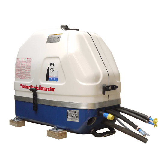
An adequate lifting yoke shall be used for transport/ Fig. 3.2-1: Lifting yoke (example) loading Scope of delivery The Fischer Panda PMS generator system contains following components: 3.3.1 Asyncron Genertoren: Fischer Panda Generator Fig. 3.3-1: Fischer Panda Generator representative picture Remote control panel Fig. - Page 30 Control Box is not required for this generators. representative picture Fischer Panda Manual Fig. 3.3.1-4: Fischer Panda Manual The Fischer Panda Manual contains following compon- ents: - Clear foil bag with general informations ect. - Generator manualwith added remote control panel manual - Spare part catalog „Installation &...
-
Page 31: Opening The Mpl Sound Insulation Capsule
Optionales components f.e.: - Fuel pump - Installation kit - Water lock - ect. Opening the MPL sound insulation capsule . To open the sound insulation capsule, the closures must Fig. 3.4-1: Sound insulation capsule, side part be rotated roughly 180° counter-clockwise. Use a fl at head screwdriver. -
Page 32: Opening The Gfk Sound Insulation Capsule
Closure open Fig. 3.4-3: Closure open 3.4.1 Opening the GFK sound insulation capsule GFK sound insulation capsule with lash closures Fig. 3.4-1: Lash closures To open the lash closures pull the handle in arrow direc- Fig. 3.4-2: Lash closures tion and lift the lash of the closure pin. After lifting of the lashes, the sound isolation cover upper pars can be removed. -
Page 33: The Panda Generator
The Panda Generator 4. The Panda Generator Type plate at the Generator Fig. 4.1-1: Type plate at the generator - Picture shows 4000s SC Fig. 4.1-2: Discription type plate 26.1.11 Panda_4000s_PMS_SCB_FCB_eng.R04 - Kapitel/Chapter 4: The Panda Generator Seite/Page 31... -
Page 34: Description Of The Generator 4000S Sc Pms
The Panda Generator 4.2 Description of the Generator 4000s SC PMS 4.2.1 Right Side View 4000s SC PMS Fig. 4.2.1-1: Right side view 01) Cylinder head 09) Combustian air intake 02) Fuel filter 10) Cooling water out at winding 03) Mechanical fuel pump 11) Cooling water in at engine 04) Speed adjust lever 12) Cooling water bypass from winding out to engine out... -
Page 35: Left Side View 4000S Sc Pms
The Panda Generator 4.2.2 Left Side View 4000s SC PMS Fig. 4.2.2-1: Left side view 01) Starter motor 10) Oil dipstick 02) Solenoid switch for starter motor 11) Oil pressure switch 03) Generator power terminal box and airfilter housing 12) Thermo switch exhaust elbow 04) Circuit breaker 015A 13) Fuel solenoid valve 05) Plug for optional electrical fuel pump... -
Page 36: Front View 4000S Sc Pms
The Panda Generator 4.2.3 Front View 4000s SC PMS Fig. 4.2.3-1: Front view 01) Cylinder head 10) Cable for control panel 02) Fuel solenoid valve 11) Connection hose for cooling circle ventilation valve 03) Ventilation screw solenoid valve 12) Passage for battery cable (-) 04) Fuel filter 13) Passage for battery cable (+) 05) Water cooled exhaust elbow... -
Page 37: Back View 4000S Sc Pms
The Panda Generator 4.2.4 Back View 4000s SC PMS Fig. 4.2.4-1: Back view 01) Starter motor 05) Air inlet 02) Generator power terminal box and airfilter housing 06) Oil drain hose 03) Front plate 07) Air filter holder 04) Ball bearing 26.1.11 Panda_4000s_PMS_SCB_FCB_eng.R04 - Kapitel/Chapter 4: The Panda Generator Seite/Page 35... -
Page 38: View From Above 4000S Sc Pms
The Panda Generator 4.2.5 View from above 4000s SC PMS Fig. 4.2.5-1: View from above 01) Generator power terminal box and airfilter housing 08) Air suction hose 02) Solenoid switch for starter motor 09) Starter motor 03) Injection nozzle 10) Cooling water connection block 04) Water-cooled exhaust elbow 11) Thermo-switch cylinder head 05) Cylinder head... -
Page 39: Description Of The Generator 4000S Fc Pms
The Panda Generator Description of the Generator 4000s FC PMS 4.3.1 Right Side View 4000s FC PMS Fig. 4.3.1-1: Right side view 01) Cylinder head 08) Generator housing with coil 02) Fuel Filter 09) Combustian air intake 03) Mechanical fuel pump 10) Cooling water out at winding 04) Speed adjust lever 11) Heat exchanger... -
Page 40: Left Side View 4000S Fc Pms
The Panda Generator 4000s FC PMS 4.3.2 Left Side View Fig. 4.3.2-1: Left side view 01) Starter motor 08) Raw water in 02) Solenoid switch for starter motor 09) Oil dipstick 03) Generator power terminal box and airfilter housing 10) Oil pressure switch 04) Circuit breaker 015A 11) Thermo switch exhaust elbow 05) Plug for optional electrical fuel pump i(inside box) -
Page 41: Front View 4000S 4000S Fc Pms
The Panda Generator 4000s FC PMS 4.3.3 Front View 4000s Fig. 4.3.3-1: Front view 01) Cylinder head 11) Connection hose for external expension tank 02) Fuel solenoid valve 12) Cable for load 03) Ventilation screw solenoid valve 13) Cable for control panel 04) Fuel filter 14) Oil drain hose 05) Water cooled exhaust elbow... -
Page 42: Back View 4000S Fc Pms
The Panda Generator 4000s FC PMS 4.3.4 Back View Fig. 4.3.4-1: Back view 01) Starter motor 04) Front plate 02) Generator power terminal box and airfilter housing 05) Ball bearing 03) Air filter holder 06) Air inlet Seite/Page 40 Panda_4000s_PMS_SCB_FCB_eng.R04 - Kapitel/Chapter 4: The Panda Generator 26.1.11... -
Page 43: View From Above 4000S Fc Pms
The Panda Generator 4000s FC PMS 4.3.5 View from above Fig. 4.3.5-1: View from above 01) Generator power terminal box and airfilter housing 08) Air suction hose 02) Solenoid switch for starter motor 09) Starter motor 03) Injection nozzle 10) Cooling water connection block 04) Water-cooled exhaust elbow 11) Thermo-switch cylinder head 05) Cylinder head... -
Page 44: Details Of Functional Units
The Panda Generator Details of Functional Units 4.4.1 Remote Control Panel - see Remote Control Panel Datasheet Remote Control Panel The remote control panel is necessary to control the generator and to evaluate the motor/generator properties. The generators will automatically cutout, if it does not run as required. The generator may not be run without the remote control panel. -
Page 45: Components Of Cooling System (Raw Water) 4000S Sc
The Panda Generator 4.4.2 Components of Cooling System (Raw water) 4000s SC Fig. 4.4.2-1: One circle system Exhaust and water outlet Water inlet 01) Cooling water in (raw water in) 07) Water connection block (cooling water out at 02) Raw water pump engine) 03) Connection hose for cooling circle ventilation valve 08) Water cooled exhaust elbow... - Page 46 The Panda Generator Raw water intake Fig. 4.4.2-2: Raw water intake The diagram shows the supply pipes for the generator. The connection neck for the raw water connection is shown on the right hand side. The cross-sec- tion of the intake pipe should be nominally larger than the generator connec- tion.
- Page 47 The Panda Generator Generator housing Fig. 4.4.2-5: Generator housing The water in is at the bottem of the Generator housing. The water out is at the top of the generator. Engine in Fig. 4.4.2-6: Engine in Engine out (water connection block) Fig.
- Page 48 The Panda Generator Injection Port Raw Water Fig. 4.4.2-8: Injection raw water The point of introduction (point of injecting) for the raw water cooled exhaust system of the marine generator is at the exhaust elbow. The exhaust elbow must be checked regularly carefully for traces by corrosion. Raw Water Output Fig.
-
Page 49: Components Of Cooling System (Raw Water + Fresh Water) 4000S Fc
The Panda Generator 4.4.3 Components of Cooling System (Raw water + Fresh water) 4000s FC Fig. 4.4.3-1: Two circle system Sea water inlet Up intake Exhaust with sea water outlet Stilling Air offtake to stilling basin's up intake basin Fresh water offtake to stilling basin's down intake 01) Cooling water in (raw water in) 07) Water connection block (cooling water out at 02) Raw water pump... - Page 50 The Panda Generator 4.4.3.1 Components of Cooling System (Raw water) 4000s FC Raw water intake Fig. 4.4.3-1: Raw water intake The diagram shows the supply pipes for the generator. The connection neck for the raw water connection is shown on the right hand side. The cross-sec- tion of the intake pipe should be nominally larger than the generator connec- tion.
- Page 51 The Panda Generator Heat exchanger Fig. 4.4.3-4: Heat exchanger The internal fresh water cooling circle is separated by the heat exchanger from the raw water cooling circle. It is reached that the raw water circle does not come with the construction units of the generator into contact. The raw water commes from the oil cooler and is led at the discharge of the heat exchanger directly into the exhaust elbow.
- Page 52 The Panda Generator 4.4.3.2 Components of Cooling System (Fresh water)4000s FC Connection external expansion tank Fig. 4.4.3-1: Connection external expansion tank The external expansion tank is connected by two hose connections. Cooling water pump Fig. 4.4.3-2: Cooling water pump The cooling water pump pumps the fresh water from the heat exchanger to the generator housing.
- Page 53 The Panda Generator Engine in Fig. 4.4.3-4: Engine in Engine out (water connection block) Fig. 4.4.3-5: Engine out Heat exchanger Fig. 4.4.3-6: Heat exchanger The heat exchanger separates the internal fresh water cooling circle from the raw water cooling circle, so that the generator components do not have contact with the raw water circulation system.
- Page 54 The Panda Generator Cooling water pump Fig. 4.4.3-7: Cooling water pump The cooling water pump pumps the fresh water from the heat exchanger to the generator housing. Seite/Page 52 Panda_4000s_PMS_SCB_FCB_eng.R04 - Kapitel/Chapter 4: The Panda Generator 26.1.11...
-
Page 55: Components Of Conbustion Air 4000S Sc + 4000S Fc
The Panda Generator 4.4.4 Components of conbustion air 4000s SC + 4000s FC Fig. 4.4.4-1: Combustion Air circle Air inlet Exhaust 01) Air inlet 04) Air in at engine 02) Generator housing with coil 05) Water cooled exhaust elbow 03) Generator power terminal box and airfilter housing 26.1.11 Panda_4000s_PMS_SCB_FCB_eng.R04 - Kapitel/Chapter 4: The Panda Generator Seite/Page 53... - Page 56 The Panda Generator Combustion air intake Fig. 4.4.4-2: Combustion air intake The sound insulated capsule for the marine generator is normally provided at the side surface with drillings, through which the combustion air can influx. Sample picture 4000s FC Cooling of the generator housing Fig.
- Page 57 The Panda Generator Exhaust elbow Fig. 4.4.4-5: Exhaust elbow At the back of the engine is the water-cooled exhaust elbow.+ Sample picture 4000s FC Exhaust outlet Fig. 4.4.4-6: Exhaust output Connect the exhaust pipe with the water lock. 26.1.11 Panda_4000s_PMS_SCB_FCB_eng.R04 - Kapitel/Chapter 4: The Panda Generator Seite/Page 55...
-
Page 58: Components Of The Fuel System 4000S Sc + 4000S Fc
The Panda Generator 4.4.5 Components of the Fuel System 4000s SC + 4000s FC Fig. 4.4.5-1: Fuel circle Fuel outlet Fuel inlet 01) Fuel in 04) Injection nozzle at engine 02) Fuel pump 05) Fuel out (Fuel return line) 03) Fuel stop solonoid Seite/Page 56 Panda_4000s_PMS_SCB_FCB_eng.R04 - Kapitel/Chapter 4: The Panda Generator 26.1.11... - Page 59 The Panda Generator Connecting pieces for the fuel pipes Fig. 4.4.5-2: Fuel connections 1. Fuel IN 2. Fuel OUT Sample picture 4000s FC Fuel pump Fig. 4.4.5-3: internal fuel pump Sample picture 4000s FC Fuel solenoid valve Fig. 4.4.5-4: Fuel solenoid valve The fuel solenoid valve opens automatically if „START“...
-
Page 60: Components Of Electrical System 4000S Sc + 4000S Fc
The Panda Generator Injection nozzle at engine Fig. 4.4.5-5: Injection nozzle at engine Sample picture 4000s FC 4.4.6 Components of Electrical System 4000s SC + 4000s FC Connection starter battery Fig. 4.4.6-1: Connections for starter battery 1. Passage for starter battery cable (plus) 2. - Page 61 The Panda Generator Electrical connections for control and load Fig. 4.4.6-2: Load At the front of the generator are also all remaining cables for the electrical connections depending upon type. 1. Remote control panel 2. AC out Sample picture 4000s FC Fuel Pump connection point Fig.
- Page 62 The Panda Generator Generator power terminal box Fig. 4.4.6-5: Generator power terminal box Above the winding housing is the generator power terminal box. In this box, the electrical connection points for the AC generator are blocked. Here is also the bridge for the protective grounding of the generator. The cover may only be removed, if it is guaranteed that the generator cannot be inadvertently started.
-
Page 63: Sensors And Switches For Operation Surveillance
The Panda Generator 4.4.7 Sensors and Switches for Operation Surveillance Thermo-switch at cylinder head Fig. 4.4.7-1: TThermo-switch at cylinder head The thermo-switch at the cylinder head serves to monitor the generator tem- perature. Sample picture 4000s FC Thermo-switch at water-cooled exhaust elbow Fig. -
Page 64: Components Of Oil Circuit 4000S Sc + 4000S Fc
The Panda Generator Oil pressure switch Fig. 4.4.7-4: Oil pressure switch In order to be able to monitor the lubricating oil system, an oil pressure switch is built into the system. Sample picture 4000s FC 4.4.8 Components of Oil Circuit 4000s SC + 4000s FC Oil filler neck with cap Fig. - Page 65 The Panda Generator Engine oil strainer Fig. 4.4.8-3: Engine oil strainer The oil strainer is normally maintenance-free; pre-supposed, the oil change intervals are kept. Sample picture 4000s FC Oil drain hose Fig. 4.4.8-4: Engine oil drain hose The Panda generator is so equipped that the engine oil can be drained by a drain hose.
-
Page 66: Preliminary Remarks
Advices regarding Starter Battery Fischer Panda recommends to use a normal starter battery. If the generator is required for extreme winter conditi- ons, the starter battery capacity should be doubled. It is recommended to regularly charge the starter battery by a suitable battery-charging device (i.e. -
Page 67: Starting Generator- See Remote Control Panel Datasheet
The Panda Generator 8. Switch the land electricity/Generator switch to zero before starting or switching off all load. The generator should only be started when all load have been switched off. The excitation of the generator will be suppressed, if the generator is switched off with load connected, left for a while, or switched on with extra load, thus reducing the residual magnetism necessary for excitation of the generator to a minimum. - Page 68 The Panda Generator Leere Seite / Intentionally blank Seite/Page 66 Panda_4000s_PMS_SCB_FCB_eng.R04 - 26.1.11...
-
Page 69: Installation Instructions
All connections (hoses, wires etc) and installation instructions are designed and suited for “standard” installation situations. In situations where Fischer Panda has no detailed information concerning certain installation requirements (such as vehicle specifications, maximum vehicle speed -and all other conditions concerning special operating situations) the installation instructions should be used as an example guide only. - Page 70 Installation Instructions Oil and fuel vapours can ignite on contact with ignition -Warning!: Danger of fire sources. Therfore: - No open flames during work on the generator. - Do not smoke. - Remove oil and fuel residues from the generator and floor. Danger!: Danger of poisoning Contact with engine oil, antifreeze and fuel can result in .
-
Page 71: Placement
Installation Instructions Placement 5.2.1 Placement and Basemount Since Panda generators have extremely compact dimensions they can be installed in tight locations, attempts are sometimes made to install them in almost inaccessible places. Please consider that even almost maintenance-free machinery must still remain accessible at least at the front (drive belt, water pump) and the service-side (actuator, dipstick). -
Page 72: General References
Installation Instructions 70 ° C (160 ° F). The on-board circuit must also be fitted with all essential fuses. ATTENTION! 7 Before working (installation) on the System read the section Cooling System Installation - Raw water See chapter 3 for the original posittion of the connections 5.3.1 General References The genset should have its own sea water (coolant water) inlet and should not be connected to any other engine systems. -
Page 73: Installation Above Waterline
A repair is then very expensive. Replacement impeller and also a spare pump should always be on board. The old pump can be sent back to Fischer Panda, where it is then economically overhauled completely. 26.1.11 Panda_4000s_PMS_SCB_FCB_eng.R04 - Kapitel/Chapter 5: Installation Instructions... - Page 74 Installation Instructions Fig. 5.3.4-1: Raw water filter 1. Raw water filter 2. Water cock 3. Hull inlet Make certain that the raw water filter lies above the water level, otherwise with cleaning water can penetrate by the hull inlet. An external pre-pump can relieve the impeller. Seite/Page 72 Panda_4000s_PMS_SCB_FCB_eng.R04 - Kapitel/Chapter 5: Installation Instructions 26.1.11...
-
Page 75: Installation Below Waterline
Installation Instructions Fig. 5.3.4-2: Installation example over the waterline FC version Raw water impeller pump Water cock Freshwater pump Raw water inlet Water-cooled exhaust elbow Expansion tank Cooling water connection block 10. Vent valve Heat exchanger 11. Oil cooler Raw water filter 12. - Page 76 Installation Instructions Cut the hose for the external vent valve... Fig. 5.3.5-1: Connection external ventilation valve Sample picture 4000s FC ...and bent it upwards. Fig. 5.3.5-2: Connection external ventilation valve Both hose ends must be led out outside of the sound cover to one point, if possible 600mm over the waterline in the midship line.
- Page 77 Installation Instructions Fig. 5.3.5-4: Installation example under the waterline FC Raw water impeller pump Water cock Freshwater pump Raw water inlet Water-cooled exhaust elbow Expansion tank Cooling water connection block 10. Vent valve Heat exchanger 11. Oil cooler Raw water filter 12.
-
Page 78: Raw Water Single Circuit Cooling System
Installation Instructions 5.3.6 Raw water single circuit cooling system Fig. 5.3.6-1: Installation example under the waterline SC 1. Vent valve 5. Raw water filter 2. Coolant connection bock 6. Sea cock 3. Exhaust elbow 7. Hull inlet 4. Raw water pump 5.3.7 Ventilating at the first filling of the Fresh water cooling circuit - FC only The Fresh water circle of the Panda 4000s FC PMS is self ven- Fig. -
Page 79: Watercooled Exhaust System
Installation Instructions 2. When the coolant level in the expansion tank do not drop any Fig. 5.3.7-2: Oil pressure switch more, disconnect the oil pressure switch. While disconnecting the oil pressure switch, the remote control panel get a „Oil pressure OK“ and the electrical colling water pump can be turned on and off by switching the panel on and off. -
Page 80: Installation Of The Water Collector
Installation Instructions Fig. 5.4.1-1: Insatalltion example - standard exhaust szstem 1. Generator 4. Silencer 2. Water lock 5. Hull outlet 3. Goose neck 5.4.2 Installation of the water collector Unfortunately, it can occasionally occur that, because of an disadvantageous mounting position of the water collec- tor, sea water gets into the diesel engines’... -
Page 81: Possible Cause: Exhaust Duct
Installation Instructions pression rings will start to corrode. These effects have to be discussed with an engine expert. It will cer- tainly be reasonable to immediately inject plenty penetrating oil through the intake stack and to slowly turn the engine with the starter motor.) The coolant can reach the exhaust area via the exhaust duct as well as via the coolant feed. -
Page 82: The Volume Of The Exhaust Water Collector
Installation Instructions Fig. 5.4.5-1: Installation area of the exhaust water collector 5.4.5.1 The volume of the exhaust water collector The exhaust water collector must be measured so large, that it can take the entire amount of water flowing back from the exhaust duct. The amount of water depends on the ducts’ length (L) and its cross section. While the diesel engine is running, coolant is continuously injected into the exhaust system and is carted outside with the emissions by the exhaust gas pressure. - Page 83 Installation Instructions Fig. 5.4.5.1-2: Testing the coolant level 26.1.11 Panda_4000s_PMS_SCB_FCB_eng.R04 - Kapitel/Chapter 5: Installation Instructions Seite/Page 81...
- Page 84 Installation Instructions 5.4.5.2 Position of the water collector Important Note! The ideal position of the water collector would be in center underneath the generator. Only in this position it is assured that the water level can not change drastically in tilted position by the water collector moving out of the center line.
- Page 85 Installation Instructions Tilted position 30 degrees Fig. 5.4.5.2-3: Tilted position 30 degrees The distance of the water level, even in ideal position, changes in a way that only 458 mm distance remain. So the critical distance is under-run already. Tilted position 45 degrees Fig.
- Page 86 Installation Instructions 5.4.5.3 Example of the installation of the water collector off-center and possible effects: The following pictures are primarily relevant for an installation of the generator with the water collector on sailing yachts. A change in the mounting position caused by tilted position does not have to be reckoned concerning motor yachts.
- Page 87 Installation Instructions Tilted position 30 degreed Fig. 5.4.5.3-3: Tilted position 30 degreed The distance between the hydrostatic head and the critical point at the exhaust elbow is only 216 mm. This means that in a tilted position of 30 degrees you already face the highest risk of sea water sloshing into the com- bustion chamber.
-
Page 88: Exhaust / Water Separator
In order to reduce the noise level of the generator unit to a minimum, an optional exhaust outlet muffler mounted next to the thru-hull fitting can be installed. Additionally there is component at Fischer Panda, which exercise both functions of a "exhaust goose neck", and the water separation. With this "exhaust/water separator" the cooling water is derived over a separate pipe. -
Page 89: Installation Exhaust/Water Separator
Installation Instructions Fig. 5.4.6-1: Exhaust/water seaparator 1. Raw water outlet ø 30mm The water flow on the exhaust/water Fig. 5.4-2: separator unit has an inner diameter (ID) of 30mm. If 2. Hose connector ø 30mm the path from the water separator to the sea water 3. -
Page 90: Fuel System Installation
Installation Instructions Fig. 5.4.7-1: Installation example - exhaust/water separator 1. Generator 4. Silencer 2. Silencer / Water lock 5. Sea cock 3. Exhast/Water-separator 6. Hull outlet If the thru-hull exhaust outlet has to be mounted far from the generator, an exhaust-water separator must definitely be installed. -
Page 91: Connection Of The Fuel Lines At The Tank
Installation Instructions Fig. 5.5.1-1: Installation example - fuel 1. Generator 5. Condensation water suction pump 2. Fuel stop cock 6. Fuel tank 3. Fuel filter 7. Fuel supply 4. Fuel return 8. Electrical fuel pump (12V-DC) (optional) 5.5.2 Connection of the fuel lines at the tank The return pipe connected to the tank must be dropped to the same depth as the suction pipe, the generfator is mounted higher than the tank, in order to prevent fuel running back into the tank after the motor has been switched off, which can lead to enormous problems if the generator switched off for a long period. -
Page 92: Position Of The Pre-Filter With Water Separator
Installation Instructions 5.5.3 Position of the pre-filter with water separator Additionally to the standard fine filter a prefilter with water Fig. 5.5.3-1: Fuel filter with water separator separator must be installed outside of the sound cover in the fuel system line. (is not included in delivery.) 5.6 Generator 12V DC System-Installation The Panda 4000s needs a battery with a capacity of at least 44Ah for the start. - Page 93 Installation Instructions The positive (+) battery cable is connected direcly to the sole- Fig. 5.6.1-1: Connection starter battery plus cable noid switch of the starter. Connection of the battery (-) Sample picture 4000s FC Connect the battery (-) with the connection point at the engine Fig.
-
Page 94: Additional Information For Battery Connection
Battery poles must be protected against short circuits by error. Inside the capsule of the Fischer Panda Generator the battery positive line must be protected against heat and vibration by a suitable conduit or sheath and must be routed that way it is not touching any area that will get hot under normal operation like entire engine itself, exhaust elbow and exhaust manifold or exhaust lines or the V-belt and pulleys. -
Page 95: Connection Of The Load
Installation Instructions Fig. 5.6.1-1: Sample diagram for starterbattery installation 5.6.2 Connection of the load Connection of the load Fig. 5.6.2-1: Connection for load Connect the load at the prepared cable 01. Cable for load Sample picture 4000s FC 26.1.11 Panda_4000s_PMS_SCB_FCB_eng.R04 - Kapitel/Chapter 5: Installation Instructions Seite/Page 93... -
Page 96: Generator Ac System-Installation
Installation Instructions 5.6.3 Connection of the remote control panel - see remote control panel datasheet Remote control panel cable Fig. 5.6.3-1: Remote control panel As standard a 7 core connection-cable, 7m long, is included in the supply. Cores are numbered from 1 to 7. The control cables are securely connected to the genset. -
Page 97: Electrical Connection Scheme
Installation Instructions 5.7.1 Electrical connection scheme Fig. 5.7.1-1: Installation example - with separat load output 1. Generator 4. Load connection 2. Starter battery 5. Battery switch 3. Remote control panel 6. Fuse All electrical safety installations have to be made on board. A power source selector switch must be installed between the generator (or if applicable, AC-Control box) and the ship´s electrical supply system. - Page 98 Installation Instructions An alternative to a manual rotating switch is an automatic power relay. When the generator is not running, the relay remains in the shore power position. As soon as the generator is running, the power relay switches automatically to the generator position.
-
Page 99: Maintenance Instructions
Personal requirements All maintenance work - if not specially marked - can be made by the trained persons. Further maintenance work must only be made by Technical personnel or Fischer Panda service points. Hazard notes for this chapter see “Safety instructions - Safety first!” on Page 14. - Page 100 Maintenance Instructions Oil and fuel vapours can ignite on contact with ignition Warning!: Danger of fire sources. Therfore: - No open flames during work on the generator. - Do not smoke. - Remove oil and fuel residues from the generator and floor. Contact with engine oil, antifreeze and fuel can result in Danger!: Danger of poisoning damage to health.
-
Page 101: Environmental Protection
Maintenance Instructions Batteries contains acid or alkalis. Warning!: Improper handling can result in battery explosion and lea- kage. Acid or alkalis can run out. An explosion of the battery is possible. See the operation and safety instruction from your battery manufacturer. -
Page 102: Engine Oil Change
Maintenance Instructions and SAE20 for temperatures between 5° C and 20°C is to be used. At temperatures under 5° C oil of the viscosity SAE10W or 10W-30 is prescribed. Type and amount of required oil see: See “Engine oil” on page 125 and “Technical Data Engine” on page 124. -
Page 103: Ventilating The Fuel System
Maintenance Instructions Open the oil filler neck Fig. 6.5.1-3: Oil fillerneck After opening the cap of the oil filler neck the new oil is refilled. Please wait instant, before measure the oil level, the oil must set off in the sump. - Page 104 Maintenance Instructions Using the lever on the fuel pump, pump by hand until the coun- Fig. 6.6.0-1: Terminal block ter pressure becomes noticeable. This builds up the primary pressure in the fuel system snd accelebrates the venting 01 02 01. Fuel pump 02.
-
Page 105: Replace Of The Fuel Filter
Maintenance Instructions 6.6.1 Checking the water separator in the fuel supply The pre-filter with water separator has a cock at its lower sur- Fig. 6.6.1-1: Fuel filter with water separator face, with this cock the downward sunk water can be dischar- ged. -
Page 106: Replace The Air Filter Element
Maintenance Instructions 6.7 Replace the air filter element Pull the holder out to change the element. Fig. 6.7-1: Air suction housing Open the air suction holder by loosen the two quick release Fig. 6.7-2: Air filter element fasteners. If no change of the cooling water level can be determined, the generator is started for 5 minutes. Afterwards repeat the de-aeration two - three times. -
Page 107: The Raw Water Circuit
Maintenance Instructions 6.7.1 Draining the coolant In principle only describes here, how the cooling water of the Fig. 6.7.1-1: Ventilation valve raw water cycle can be drained. See measures for the prepara- tion of the winter storage. The simplest and cleanest method consists of the fact to bring the external ventilation valve below the generator level and hold over a collecting basin. -
Page 108: Replace The Impeller
Maintenance Instructions impeller are exposed to very strong loads. This can shorten the life span extremely. Further the operation of the impeller pump loaded in waters with a high portion of suspended matters. The use of the impeller pump is particu- larly critical in coral waterbodies. -
Page 109: Conservation At Longer Operation Interruption
Maintenance Instructions Pull to the impeller with a multigrip pliers of the wave. Fig. 6.8.3-4: Impeller Check to the impeller for damage and replace it if necessary. Fig. 6.8.3-5: Impeller Before the reinsertion into the housing the impeller should have been lubricated with glycerin or with a non-mineral oil based lubricant e.g. -
Page 110: Initiation At Spring
Maintenance Instructions ner. The circuit must be kept upright some minutes to guaranteed that the anti-freeze protection mixture reaches all ranges of the cooling system. 2. The concentration of the anti-freeze mixture in the internal cooling circuit must be checked with a suitable measu- ring instrument. - Page 111 • Start generator and check the basic adjustments of the generator such as voltage, speed regulation etc.. • Check all switching off devices for function by operational procedures. Fischer Panda does not take over adhesion for possible damages! 26.1.11 Panda_4000s_PMS_SCB_FCB_eng.R04 - Kapitel/Chapter 6: Maintenance Instructions...
- Page 112 Maintenance Instructions Leere Seite / Intentionally blank Seite/Page 110 Panda_4000s_PMS_SCB_FCB_eng.R04 - 26.1.11...
-
Page 113: Generator Failure
Generator Failure 7. Generator Failure Personal requirements The work described here, unless otherwise indicated, are performed by the operator. More Irepair work may be performed only by specially trained personnel or by authorized repair shops (Fischer Panda service points). This is especially for working on the valve timing, fuel injection system and the engine repair. Safety instructions for this chapter see “Safety instructions - Safety first!”... - Page 114 Generator Failure Oil and fuel vapours vcan ignite on contact with ignition Warning!: Danger of fire sources. Therfore: - No open flames during work on the generator. - Do not smoke. - Remove oil and fuel residues from the generator and floor. Contact with engine oil, antifreeze and fuel can result in Danger!: Danger of poisoning damage to health.
-
Page 115: Tools And Measuring Instruments
Generator Failure Tools and measuring instruments In order to be able to manage disturbances while driving, following tools and measuring instruments should belong to the equipment on board: • Multimeter for voltage (AC), frequency and resistance • Measuring instrument for inductance •... -
Page 116: Automatic Voltage Monitoring And Auto-Shut Down
Generator Failure 7.4.1 Monitoring the Generator Voltage Notice!: see “Safety instructions - Safety first!” on Page 14. Follow the general safety instruction at the front of this manual. The voltage range of the power stations normally lies between 100V and 130V in the 60Hz version. In some coun- tries even substantially larger tension deviations are being called "normally". -
Page 117: Discharge The Capacitors
Generator Failure 7.5.1 Discharge the capacitors 1) Switch off generator Fig. 7.5.1-1: Capacitors 2) Disconnect starter battery 3) Generator power terminal box 4) Remove the caps The capacitor is discharged, by short circuit the two contacts. In addition use the cone end of an isolated screwdriver. Sample picture 4000s FC 7.5.2 Check and discharge the capacitors ATTENTION! - Page 118 Generator Failure Discharge the capacitor - single phase Fig. 7.5.2-1: Discharge capacitor single phase 03. Capacitor Discharge the capacitor - three phase Fig. 7.5.2-2: Discharge capacitor three phase 01. Discharge reactor (5-10kOhm) 02. Multimeter 03. Capacitor At three phase capacitors the dicharge must be made bet- ween every phase (L1-L2;...
-
Page 119: Checking The Generator Voltage
Generator Failure deterioration of the capacitors. 7.5.3 Checking the generator voltage In order to test, whether the fixed winding produces enough voltage, proceed in such a way: 1. Guarantee that the connection to the electrical system is interrupted. 2. Remove all conductions in the power terminal box of the generator. 3. -
Page 120: Measuring The Inductive Resistance
Generator Failure Fig. 7.5.5-1: Coilplan If a pass (beep) should be determined, the generator must be returned for examination in the plant, or it can also be wound again locally. For this coil datas can be requested. 7.5.6 Measuring the inductive resistance Unfortunately the checking of the ohmic resistance permits still no reliable statement about the condition of the coil. -
Page 121: Damage To Starter Motor
Generator Failure 1. Fuel solenoid valve Fig. 7.6.1-1: Fuel solenoid valve 2. Ventilation screw Sample picture 4000s FC 7.6.2 Damage to starter motor The starter is fitted with a free wheel or axial rotating spring cog, which prevents the starter being driven externally by means of the motor. - Page 122 Generator Failure Leere Seite / Intentionally blank Seite/Page 120 Panda_4000s_PMS_SCB_FCB_eng.R04 - 26.1.11...
-
Page 123: Tables
Tables 8. Tables Troubleshooting GENERATOR OUTPUT VOLTAGE TOO LOW For 60Hz versions: less than 100V Cause Solution Generator is overloaded. Reduce the electrical load. (Switch off load) Motor is not reaching the rated rpm. Refer to "motor faults" section. Defective capacitor(s). Check capacitors and replace if necessary. - Page 124 Tables STARTER IS TURNING MOTOR, BUT FAILS TO START Cause Solution Fuel inlet solenoid valve not opening. Check wire connections and circuitry to solenoid valve. (ref. DC wiring diagram: Relay K2, Fuse) Fuel pump not working. Check fuel-filter and pump: clean if necessary. Lack of fuel.
- Page 125 Tables MOTOR SPEED DROPS Generator overloaded by over-energizing. Check that the proper capacitor type is installed and that they are connected correctly. Defective generator (windings, bearings, or other). Generator must be sent to manufacturer for repair of damaged bearings or winding. Damaged engine.
-
Page 126: Technical Data Engine
Tables 8.2 Technical Data Engine Fig. 8.2-1: Technical Data Engine Type Farymann 18W430 Govenor mechanical Cylinder Bore 82 mm Stroke 55 mm Stroke volume 290 cm max. power (DIN 6271 IFN-ISO) 5,7 kW Nominal speed 60 Hz 3600 rpm 3690 rpm Idle running speed Valve clearance (engine cold) 0,2 mm... -
Page 127: Engine Oil
API CDEngine oil for suction- and turbo diesel engine API CFReplace the specification API CD since 1994 API CGEngine oil for highest demands, turbo-tested For the Fischer Panda Generator the API CF Oil is needed. Engine oil type over 25°C... -
Page 128: Coolant Specifications
Use a mixture of water and antifreeze. The antifreeze needs to be suitable for aluminium. The antifreeze concentra- tion must be regularly checked in the interests of safety. Fischer Panda recommend to use the product: GLYSANTIN PROTECT PLUS/G 48 Engine coolant automotive industry Product description Product name GLYSANTIN ®... -
Page 129: Fuel
Tables Fuel Use a clean No. 2 Diesel fuel oil (SAE J313 JUN87) according to ASTM D975 and EN 590. Do not use alternative fuel, because its quality is unknown or it may be inferior in quality. Kerosene, which is very low in cetane rating, adversely effects the engine. 26.1.11 Panda_4000s_PMS_SCB_FCB_eng.R04 - Kapitel/Chapter 8: Tables Seite/Page 127... -
Page 130: Capsule Measurments
Z:\Inventor\P 4\P 04 synchro SCB\Kapsel.idw Ra 12,5 (157) Exhaust passage Water inlet passage Fuel in Fuel out Power Panel accumulator (+) accumulator (-) Air inlet Maßstab: Gewicht: Material: Halbzeug: Artikel Nr.: Otto-Hahn-Str. 32-34 D-33104 Paderborn Tel.: (05254) 9202-0 Fax (05254) 9202-550 info@fischerpanda.de www.fischerpanda.de Datum Name Bearb. -
Page 131: Remote Control Panel P4 Control
Remote Control Panel P4 Control Fischer Panda Datenblatt / Datasheet 9. Remote Control Panel P4 Control Art Nr. 21.02.02.032H Bez. Remote Control Panel P4 Control Dokument Hardware Software Aktuell: V1.00 -------------------------- Ersetzt: V1.00 -------------------------- Remote control panel Remote control panelP4 Control The remote control panel is necessary to control the generator and to evaluate the motor/generator properties. - Page 132 Remote Control Panel P4 Control Fischer Panda Datenblatt / Datasheet 9.1.1 Cleaning and Replacing parts at the generator Attention!: Disconnect the battery when working on the generator The battery must always be disconnected (first negative then positive pole), when work on the generator or the electrical system of the generator are made, so that the generator can not be started accidentally.
-
Page 133: Back Side
Remote Control Panel P4 Control Fischer Panda Datenblatt / Datasheet Front side Fig. 9.2-1: Remote Control Panel - Front Side 01) Diplay operating hours 05) Warning light for engine temperature 02) Power „ON/OFF“-button 06) Warning light for exhaust temperature 03) Generator „Start“-button 07) Warning light for oil pressure 04) Control light „Override“... -
Page 134: Operation Manual
Advices concerning the starter battery Fischer Panda recommends normal starter battery use. If a genset is required for extreme winter conditions, then the starter battery capacity should be doubled. It is recommended that the starter battery be regularly charged by a suitable battery-charging device (i.e., at least every 2 months). -
Page 135: Starting The Generator
Remote Control Panel P4 Control Fischer Panda Datenblatt / Datasheet Leaks at hose connections must be immediately repaired, especially the raw water impeller pump. It is certainly possible that the raw water impeller pump will produce leaks, depending upon the situation. (This can be caused by sand particles in the raw water etc.) In this case, immediately exchange the pump, because the dripping water... -
Page 136: Installation Of The Panel
Remote Control Panel P4 Control Fischer Panda Datenblatt / Datasheet Notice!: Never switch off the battery until the generator has stopped. 5. If necessary, close sea cock. :Notice!: If the generator switches itself off with the operation with load for temperature reasons, must be examined immediately, which the cause is. -
Page 137: Jumperconfiguration
Remote Control Panel P4 Control Fischer Panda Datenblatt / Datasheet T-EXH Error „exhaust temp.“. Temperature switch exhaust elbow in. Can be setted up by jumper as NC or NO Gives 22mA (12V +) on the switch. Status is displayed by green/red LED. - Page 138 Remote Control Panel P4 Control Fischer Panda Datenblatt / Datasheet Temp. switch engine head is NO J102 Temp switch exhaust elbow is NC Temp switch exhaust elbow is NO J103 Oil pressure switch is NC Oil pressure switch is NO Seite 136 - Kapitel 9: Remote Control Panel P4 Control P4_Control_eng.fm...
-
Page 139: Maximum Ratings
Remote Control Panel P4 Control Fischer Panda Datenblatt / Datasheet 9.5.3 Jumper for configuraton odf the „Override“ time J104 J105 J106 Test-Mode Override time [s] open open open closed open open open closed open closed closed open open open closed... - Page 140 DC power supply Temperature fail - engine open-fail/closed-OK (input -> GND) Temperature fail - exhaust open-fail/closed-OK (input -> GND) oil pressure fail open-fail/closed-OK (input -> GND) start (output -> +) fuel (output -> +) Panel P04...
Need help?
Do you have a question about the 4000s PMS SC and is the answer not in the manual?
Questions and answers