Sign In
Upload
Manuals
Brands
Fischer Panda Manuals
Portable Generator
AGT 45-VS PMS
User Manuals: Fischer Panda AGT 45-VS PMS Generator
Manuals and User Guides for Fischer Panda AGT 45-VS PMS Generator. We have
1
Fischer Panda AGT 45-VS PMS Generator manual available for free PDF download: Manual
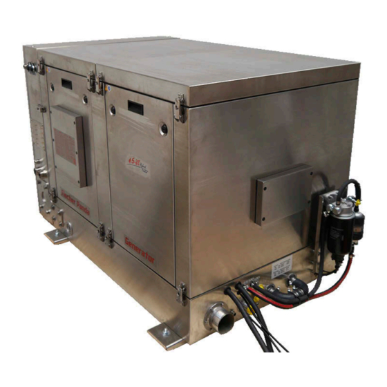
Fischer Panda AGT 45-VS PMS Manual (186 pages)
Super silent technology 300-500 VDC/150 ADC/0-45 kW
Brand:
Fischer Panda
| Category:
Portable Generator
| Size: 9 MB
Table of Contents
Panda 45-VS PMS Manual
1
Current Revision Status
2
Table of Contents
3
General Instructions and Regulations
10
The Cardinal Rule Is Safety
10
Disposal
11
Customer Registration and Warranty
12
Technical Support
12
Caution, Important Information for Start-Up
12
Safety Instructions - Safety First
13
Safe Operation
13
Observe the Safety Instructions
13
Personal Protective Clothing
13
Cleanliness Ensures Safety
13
Safe Handling of Fuels and Lubricants
14
Exhaust Fumes and Fire Protection
14
Safety Precautions against Burns and Battery Explosions
15
Protect Your Hands and Body from Rotating Parts
15
Antifreeze and Disposal of Fluids
15
Implementation of Safety Inspections and Maintenance
15
Warning and Instruction Signs
16
Special Instructions and Hazards of Generators
16
Protective Conductor and Equipotential Bonding
16
Switch off All Loads When Working on the Generator
17
Potential Equalisation in Panda AGT-DC and VS Generators
17
Safety Instructions Concerning Cables
17
General Safety Instructions When Handling Batteries
17
In Case of Emergency First Aid
19
When an Adult Stops Breathing
20
Special Instructions and Hazards in the Case of VS-DC Generators
21
General Safety Instructions for Operating a VS-DC Generator
21
Hybrid-Charger" Power Electronics
21
Fire Protection Measures
22
Insulation Monitoring Measures
22
Basics
23
Proper Use
23
Objectives of the Manual and Declaration of Interested Parties
23
Specialists
23
Users
23
Operators
24
Opening the Fischer Panda Transport Box
24
Bolted Fischer Panda Transport Box
24
Fischer Panda Transport Box with Metal Tab Closure
24
Transport and Loading
24
Transporting the Generator
24
Loading the Generator
24
Fischer Panda Generator Scope of Delivery
25
Variable Speed Generators
25
Opening the MPL Sound Insulation Capsule
27
Special Servicing Instructions and Measures for Extended Downtime and Decommissioning
29
Instructions Regarding the Starter Battery During Extended Downtime
29
Measures for Short-Term Downtimes
30
Measures for Medium-Term Downtimes / Hibernation
30
Surface Protection Measures
30
Measures for Removing Surface Protection after Medium-Term Downtimes (3 to 6 Months)
31
Measures for Long-Term Downtime / Decommissioning
31
Surface Protection Measures
31
Measures for Removing Preservatives after Long-Term Downtime / Recommissioning (more than 6 Months)
32
EC Declaration of Conformity
35
UKCA Declaration of Conformity
37
The Panda Generator
39
Position of the Identification Plate
39
Description of the Generator
40
Right-Hand Side View
40
Left-Hand Side View
42
Front View
43
Rear View
45
Top View
47
Function Groups and Functional Diagrams
48
Fpcontrol Panel
48
The Cooling System
49
Fuel System
50
Combustion Air System
51
Electrical System
52
Lubricant System
53
Sensors and Switches for Operational Monitoring
54
Installation Instructions
55
Personnel
55
Hoisting Procedure
55
Placement
57
Preliminary Remarks
57
Installation Location and Base
57
Advice for Optimal Sound Insulation
58
Generator Connections
59
Connecting the Cooling System - Raw Water
61
General Instructions
61
Arrangement of the Through-Hull Fitting in Yachts - Schematic
61
Quality of the Raw Water Suction Line
61
Installation of the Generators above the Waterline
61
Raw Water Installation Diagram
62
Installing the Generator below the Waterline
63
Raw Water Installation Diagram
64
Installation of the Standard Exhaust System - Diagram
65
Layout of the Exhaust System
65
Installation of the "Water Lock
65
Potential Causes for Water in the Exhaust Line
66
Potential Cause: Exhaust Line
66
Potential Cause: Coolant Line
66
Installation Location of the Exhaust Water Lock
66
The Volume of the Exhaust Water Lock
67
Ideal Position of the Water Lock
67
Example for the Installation of the Water Lock Outside of the MID-Line with Possible Con- Sequences
69
Exhaust/Water Separator
71
Installing the Exhaust/Water Separator - Schematic
71
Connecting the Cooling System - Raw Water
73
Position of the External Cooling Water Expansion Tank
73
Installing the Fuel System
75
Connecting the Fuel Line to the Tank
76
Bleeding the Fuel Lines
76
Installing the Generator DC System
77
General Safety Instructions When Dealing with Batteries
77
Connecting the Starter Battery
78
Installation of the Starter Battery Connection Lines
78
Connecting the Remote Control Panel
80
Electrical Connections
80
Start-Up
84
Generator Operating Instructions
85
Personnel
85
Safety Instructions Regarding Operation
85
General Instructions Regarding Operation
86
Operating at Low Temperatures
86
Pre-Heating the Diesel Engine
86
Tips Regarding the Starter Battery
86
Operating at Reduced Load and Idling
86
Reasons for Carbon Building up in the Generator
86
In Order to Avoid Generator Sooting, Take Note of the Following Items
86
Load Placed on the Engine in Continuous Use and Overloading
87
Protection Conductor
87
Operational Monitoring System on the Fischer Panda Generator
87
Checks before Starting - See the Remote Control Panel Data Sheet
87
Starting the Generator - See Remote Control Panel Data Sheet
87
Switching off the Generator - See Separate Remote Control Panel Data Sheet
88
Generator Faults and Errors
89
Personnel
89
Hazard Warnings for this Chapter
89
Tools and Measuring Instruments
91
Overloading the Generator
91
Generator Output Voltage Is too Low
92
Starting Problems
92
Clogged Fuel Filter
92
Troubleshooting Table
92
Faults on the Hatz Engine
93
Hatz ECU Fault Code Table
93
Maintenance Instructions
103
Personnel
103
Hazard Warnings for Maintenance
103
Disposal of Engine Fluids
104
Important Information
105
Checking Hose Elements and Rubber Parts in the Noise Attenuation Capsule
105
Exhaust Gas Lines and Hoses
105
Securing the Generator to Prevent It from Being Switched on Unintentionally
105
Opening the Capsule
106
Maintenance Instructions
108
Maintenance Work
108
Checking the Oil Level
109
Topping up the Oil
110
After Checking the Oil and Topping up
110
Checking the Intake Area of the Combustion Air
111
Checking the Cooling System
113
Changing the Engine Oil and Oil Filter
114
After the Oil Change
116
Exchanging the Fuel Pre-Filter
117
Exchanging the Main Fuel Filter
118
Checking the Poly V-Belt
119
Exchanging the Oil Separator of the Crankcase Vent
120
Checking the Threaded Connections
121
Checking/Exchanging the Fuses
122
Checking/Exchanging the Relays
124
Exchanging the Air Filter Cartridge
127
Draining the Water Separator
130
Exchanging the Poly V-Belt
132
1Checking the Belt Tension
133
Checking the Condition of the Starter Battery
134
Aerating (Bleeding) the Fuel System
134
Maintaining the Raw Water Circuit
135
1Cleaning the Raw Water Filter
135
2Raw Water Pump and Impeller
135
3Exchanging the Impeller
136
Filling the Fresh Water System
138
Annex
141
Technical Data
141
Technical Data for Engine
141
Technical Data for Generator
141
Engine Oil Specification
141
Coolant Specification
141
Fuel Specification
141
Dimensions
142
Current Revision Status
144
Download
145
Panda Fpcontrol Safety Instructions
147
Personnel
147
Safety Instructions
147
Function Description
148
Proper Use
148
Panda Fpcontrol
149
Components of the Fpcontrol
149
Fpcontrol - CP-G
149
Environmental Specifications, Physical Data of the Fpcontrol CP-G
149
Fpcontrol - GC-S
150
Environmental Specifications, Physical Data of the Fpcontrol GC-S
150
Fpcontrol CB-G
150
Fpcontrol CB-G Connections
151
Environmental Specifications, Physical Data of the Fpcontrol CB-G
151
Fpcontrol CAN Interface - SAE J1939 (Fpcontrol CI-SAE J1939)
151
Fpcontrol CI-SAE J1939 Connections
152
Environmental Specifications, Physical Data of the Fpcontrol CI-SAE J1939
152
Fpcontrol Measurement Unit - MU-3Ph/DC (Fpcontrol MU-3Ph/DC)
152
Fpcontrol MU-3Ph/DC Connections
153
Environmental Specifications, Physical Data of the Fpcontrol MU-3Ph/DC
153
Fpcontrol Measurement Unit - MM-3 (Fpcontrol MM-3)
153
Environmental Specifications, Physical Data of the Fpcontrol MM-3
154
Installation
154
Installation of the Electronic Control Unit (ECU) Fpcontrol - GC-S
154
Installation of the Connection Box Fpcontrol - CB-G
154
Installation of the Fpcontrol - CP-G
154
Operation
155
Switching on the Generator
155
Overview Page with Autostart Activated
156
The Fpcontrol VCS Overview
157
The Fpcontrol AGT Overview
160
Battery Guard
162
Functional Description of the UIU Charging Process
162
The Fpcontrol Inverter Overview
164
Starting up the Generator
168
Preparations for Starting up / Checks (Daily) for Marine Version
168
Preparations for Starting up / Checks (Daily) for Vehicle Version
168
Starting up the Generator
169
Stopping the Generator
170
The Menu
171
Main Menu
171
Sub-Menu: "Panel
171
Setting the Illumination of the CP-G
172
Setting the Contrast of the CP-G
172
Setting the Standby Time of the CP-G
173
Setting the Standby Illumination of the CP-G
173
Setting the Display Mode of the CP-G Overview Page
173
Setting the Language of the Text Pages of the CP-G
173
Setting the Temperature Unit
174
Setting the Aural Alarm
174
Setting the Display to Flash in the Event of a Fault
174
10Setting the Panel Heating
175
11Setting the Display of the Optional Measurement Data
175
12Supplementary Start-Up Functions
175
13Resetting All Values of the Panel Sub-Menu to Default Values
176
14Return to Main Menu
176
Sub-Menu: "Generator
176
Setting the Autostart of the CP-G
177
Setting the Optional Water Pump/Fan DC Output of the CP-G
178
Switching the Switching Outputs of the CP-G
178
Reading out the Event Memory of the CP-G
178
Resetting All Values of the Generator Sub-Menu to the Default Values
179
Returning the Main Menu
179
Resetting the Panel Language to the Default (English)
179
How to Set the Panel Language after a Reset
179
Faults
180
Symbols and Messages on the Display
180
Example of Message - "Sensor Defective
180
Example of Message - "Sensor/Cable Break
180
Error Code
180
Table of Faults
181
Description of the Symbols
183
Accessories
184
Dimensional Drawing
186
Advertisement
Advertisement
Related Products
Fischer Panda Panda AGT 6000
Fischer Panda AGT 6000
Fischer Panda AGT 6000 PVMV-N
Fischer Panda AGT 4000 B
Fischer Panda Panda AGT 6000-8000 PVMV-N
Fischer Panda AGT 8000 PMS
Fischer Panda AGT 4000 PVMV-N
Fischer Panda 0032820
Fischer Panda 0032821
Fischer Panda 10000 NE
Fischer Panda Categories
Portable Generator
Inverter
Controller
Control Panel
Control Systems
More Fischer Panda Manuals
Login
Sign In
OR
Sign in with Facebook
Sign in with Google
Upload manual
Upload from disk
Upload from URL