Advertisement
- 1 Introduction
- 2 Package Contents
- 3 Installation Requirements
- 4 System Requirements
- 5 Wireless Adoption Requirements
- 6 Network Topology Requirements
- 7 Hardware Overview
- 8 Hardware Installation
- 9 Connecting Ethernet
- 10 Powering the UniFi AP
- 11 Wireless Adoption
- 12 Software Installation
- 13 Mobile App Installation
- 14 Specifications
- 15 Documents / Resources
Introduction
Thank you for purchasing the Ubiquiti Networks® UniFi® 802.11AC 3x3 MIMO Outdoor Access Point with Plug & Play Mesh Technology. This Quick Start Guide is designed to guide you through installation and includes warranty terms.

The UAP-AC-M-PRO requires the UniFi Controller v5.1.1 or newer, available at: downloads.ubnt.com/unifi
Package Contents

TERMS OF USE: Ubiquiti radio devices must be professionally installed. Shielded Ethernet cable and earth grounding must be used as conditions of product warranty. TOUGHCable™ is designed for outdoor installations. It is the customer's responsibility to follow local country regulations, including operation within legal frequency channels, output power, and Dynamic Frequency Selection (DFS) requirements.
Installation Requirements
- 13 mm wrench (for pole mounting)
- Cable feed must be pointed downwards when mounted.
- Shielded Category 5 (or above) cabling should be used for all outdoor wired Ethernet connections and should be grounded through the AC ground of the PoE.
We recommend that you protect your networks from harmful outdoor environments and destructive ESD events with industrial-grade, shielded Ethernet cable from Ubiquiti Networks. For more details, visit: www.ubnt.com/toughcable
System Requirements
- Linux, Mac OS X, or Microsoft Windows 7/8/10
- Java Runtime Environment 1.6 (1.8 or newer recommended)
- Web Browser: Google Chrome (Other browsers may have limited functionality)
- UniFi Controller software v5.1.1 or newer, available at: downloads.ubnt.com/unifi
Wireless Adoption Requirements
The UAP-AC-M-PRO supports wireless adoption into your UniFi Wi-Fi network. This feature requires a currently managed UniFi AP operating with the following configuration:
- The UniFi AP must be running firmware 3.7.7 or newer
- At least one SSID enabled and operating on 5 GHz band
- The UAP-AC-M-PRO must be within wireless range of the UniFi AP
Network Topology Requirements
- A DHCP-enabled network (for the UniFi device to obtain an IP address as well as for the wireless clients after deployment)
- A UniFi Cloud Key or management station running the UniFi Controller v5.1.1 (or newer) software, located either on-site and connected to the same Layer-2 network, or off-site in the cloud or NOC
Sample Network Diagram:

All UniFi devices support off-site management controllers. For setup details, see the User Guide on the website: documentation.ubnt.com/unifi
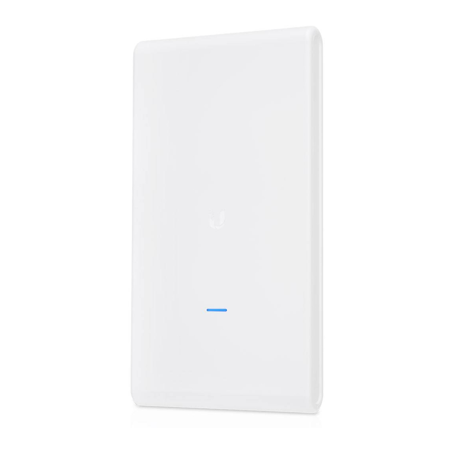
Hardware Overview
LED

| LED Color | Status |
| Flashing White | Initializing. |
| Steady White | Factory default, waiting to be integrated. |
| Alternating White/Blue | Device is busy; do not touch or unplug it. This usually indicates that a process such as a firmware upgrade is taking place. |
| Quickly Flashing Blue | Used to locate and identify a UniFi device. When the Locate feature is activated in the UniFi Controller software, the Status LED will flash blue. It will also display the location of the device on the map. |
| Steady Blue | Indicates the device has been successfully integrated into a network and is working properly. |
| Steady Blue with occasional flashing | Indicates the device is in an isolated state (all WLANs are brought down until an uplink is found). |
Ports

Secondary The Secondary port is a Gigabit Ethernet port used for bridging.
Reset The Reset button serves two functions for the UniFi AP:
- Restart Press and release the Reset button quickly.
- Restore to Factory Default Settings Press and hold the
Reset button for more than five seconds.
Main The Main port is a Gigabit PoE port used to connect the power and should be connected to the LAN and DHCP server. Power can be provided by one of the following:
- Gigabit PoE Adapter (included)
- Ubiquiti Networks UniFi Switch with PoE
- 802.3af/802.3at PoE+ compliant switch
Hardware Installation
The UAP-AC-M-PRO includes hardware for mounting on a pole or mast. Alternatively, it can be installed on a wall using additional fastening hardware.
Pole Mount
- Insert two Carriage Bolts into each Pole Clamp and attach a Flange Nut on each bolt.

![warning]() Note: The mounting assembly can accommodate a Ø 38 - 76 mm pole.
Note: The mounting assembly can accommodate a Ø 38 - 76 mm pole.
- Attach one of the Pole Clamps to the pole by sliding the Carriage Bolts around the pole and into the top two slots of the Mounting Bracket.

- Uniformly hand-tighten each Flange Nut. Ensure the Pole Clamp is evenly clamped around the pole and tighten each Flnge Nut to approximately 25 N-m.
- Repeat steps 2 and 3 for the second Pole Clamp.

- Attach the UniFi AP to the Mounting Bracket:
- Position the UniFi AP with the Mounting Bracket aligned between the mounting tabs on the back of the UniFi AP.
- Slide the UniFi AP downward into the grooves of the Mounting Bracket until the snap pins engage and lock the UniFi AP in place.


Wall Mount
To mount the UniFi AP on a wall, securely attach the Mounting Bracket to the wall using four fasteners (not included).
 Note: The Mounting Bracket must attach directly to a stud or other structurally stable surface.
- Locate the stud.
- Position the Mounting Bracket on the stud, ensuring at least two holes are centered on the stud.
- Mark all four holes on the wall.
- Drill pilot holes as necessary.
- Secure the Mounting Bracket to the wall with four fasteners.


- Attach the UniFi AP to the Mounting Bracket:
- Position the UniFi AP with the Mounting Bracket aligned between the mounting tabs on the back of the UniFi AP.
- Slide the UniFi AP downward into the grooves of the Mounting Bracket until the snap pins engage and lock the UniFi AP in place.


Connecting Ethernet
- Press down on the center of the port cover and slide it downward to remove it.


- Connect an Ethernet cable to the Main port.

- Replace the port cover.

Powering the UniFi AP
Power the UniFi AP with the included Power Adapter or an 802.3af PoE switch.
Powering with a PoE Adapter
- Connect the Ethernet cable from the UniFi AP to the POE port of the Gigabit PoE adapter.
- (Optional for non-mesh setup) Connect an Ethernet cable from your LAN to the LAN port of the Gigabit PoE adapter.
- Connect the Power Cord to the adapter, and then plug the Power Cord into a power outlet.


Mounting the PoE Adapter (Optional)
- Remove the PoE Mounting Bracket from the adapter, place the bracket at the desired location, and mark the two holes.
- Pre-drill the holes if necessary, and secure the bracket using two fasteners (not included).
- Align the slots on the adapter with the tabs of the PoE Mounting Bracket, and then slide the adapter down.
")
")
Powering with a PoE Switch
Connect the Ethernet cable from the UniFi AP directly to a PoE port on an 802.3af switch. PoE will automatically be enabled.
Connected to UniFi Switch, model US-24-250W
Wireless Adoption
See the Wireless Adoption Requirements before proceeding.
- Ensure the UAP-AC-M-PRO is powered on, and then launch the UniFi Controller software.
- Go to the Devices page, and the UAP-AC-M-PRO will show up as Pending Approval (Wireless).
- Click Adopt.
For information on configuring and using the UniFi Controller software, refer to the User Guide located on our website: documentation.ubnt.com/unifi
Software Installation
If you are not running the UniFi Controller software version 5.1.1 or newer, download and install the latest version from: documentation.ubnt.com/unifi
Launch the software and follow the on-screen instructions. Step-by-step instructions are available in the User Guide.
After you have installed the software and run the UniFi Installation Wizard, a login screen will appear for the UniFi Controller management interface. Enter the Username and Password that you created and click Log In.

You can adopt devices, manage your wireless network, and view network statistics using the UniFi Controller management interface.
Mobile App Installation
Ubiquiti Networks also offers the UniFi mobile app, which is available from the App Store (iOS) or Google Play™ Store (Android).


You can use it to provision a UniFi AP for basic functionality without configuring a UniFi Controller. It also allows seamless provisioning of APs for remote controllers (controllers not on the same layer-2 network) and easy access to both local controllers and those monitored on unifi.ubnt.com.
Specifications
| UAP-AC-M-PRO | |
| Dimensions | 343.2 x 181.2 x 60.2 mm (13.51 x 7.13 x 2.37") |
| Weight | 633 g (1.40 lb) |
| Networking Interface | (2) 10/100/1000 Ethernet Ports |
| Buttons | Reset |
| Power Method | 802.3af PoE |
| Power Supply | 48V, 0.5A PoE Gigabit Adapter (Included) |
| Supported Voltage Range | 44VDC to 57VDC |
| Max. Power Consumption | 9W |
| Max. TX Power 2.4 GHz 5 GHz | 22 dBm 22 dBm |
| MIMO 2.4 GHz 5 GHz | 3 x 3 3 x 3 |
| Throughput Speeds* 2.4 GHz 5 GHz | 450 Mbps 1300 Mbps |
| Range* | 183 m (600 ft) |
| Antennas | (3) Dual-Band Internal |
| Antenna Gain | 8 dBi |
| Wi-Fi Standards | 802.11 a/b/g/n/ac |
| Wireless Security | WEP, WPA-PSK, WPA Enterprise (WPA/WPA2, TKIP/AES) |
| BSSID | Up to Four per Radio |
| Mounting | Wall/Pole (Pole Kit Included) |
| Operating Temperature | -40 to 70°C (-40 to 158°F) |
| Operating Humidity | 5 - 95% Noncondensing |
| Certifications | CE, FCC, IC |
* Speed and Range values may vary and are based on optimal environments.

Documents / Resources
References
Download manual
Here you can download full pdf version of manual, it may contain additional safety instructions, warranty information, FCC rules, etc.
Download Ubiquiti UniFi AC MESH PRO UAP-AC-M-PRO Quick Start
Advertisement


Need help?
Do you have a question about the UniFi AC MESH PRO and is the answer not in the manual?
Questions and answers