Ubiquiti PowerBeam M5, PowerBeam M5-300 Manual
- Quick start manual (25 pages) ,
- Quick start manual (25 pages)
Advertisement
Introduction
This Quick Start Guide is designed to guide you through the installation, and show you how to access the airOS® Configuration Interface. This Quick Start Guide also includes the warranty terms and is for use with the PowerBeamM5, model PBE-M5-300.
Package Contents

TERMS OF USE: Ubiquiti radio devices must be professionally installed. Shielded Ethernet cable and earth grounding must be used as conditions of product warranty. TOUGHCable™ is designed for outdoor installations. It is the customer's responsibility to follow local country regulations, including operation within legal frequency channels, output power, and Dynamic Frequency Selection (DFS) requirements.
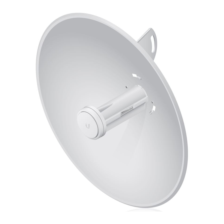
Hardware Overview
Bottom View

Reset Button
To reset to factory defaults, press and hold the Reset button for more than 10 seconds while the PowerBeam is already powered on.
Release Button
After you assemble the PowerBeam, check the Release button; it should be fully engaged in the Release Button Slot of the Rear Housing. This ensures that the Antenna Feed is locked into place. If you need to remove the Antenna Feed, you must depress the Release button first.
LEDs

 Signal In airOS, you can modify the wireless signal strength threshold values for each LED on the Advanced tab under Signal LED Thresholds. The default values are shown below:
![]() LED will light green when the wireless signal strength is above -65 dBm.
LED will light green when the wireless signal strength is above -65 dBm.
![]() LED will light green when the wireless signal strength is above -73 dBm.
LED will light green when the wireless signal strength is above -73 dBm.
![]() LED will light amber when the wireless signal strength is above -80 dBm.
LED will light amber when the wireless signal strength is above -80 dBm.
![]() LED will light red when the wireless signal strength is above -94 dBm.
LED will light red when the wireless signal strength is above -94 dBm.
![]() Ethernet The Ethernet LED will light steady green when an active Ethernet connection is made and flash when there is activity.
Ethernet The Ethernet LED will light steady green when an active Ethernet connection is made and flash when there is activity.
![]() Power The Power LED will light green when the device is connected to a power source.
Power The Power LED will light green when the device is connected to a power source.
Application Examples
The PowerBeam mounted outdoors with the Dish Reflector installed provides directional outdoor coverage (gain is reflector-dependent).

The PowerBeam mounted outdoors without the Dish Reflector installed provides outdoor-to-indoor coverage using the 3 dBi Antenna Feed only.

Installation Requirements
- 10 mm wrench
- Shielded Category 5 (or above) cabling should be used for all wired Ethernet connections and should be grounded through the AC ground of the PoE.
We recommend that you protect your networks from the most brutal environments and devastating ESD attacks with industrial-grade shielded Ethernet cable from Ubiquiti Networks. For more details, visit www.ubnt.com/toughcable
Installation
- Align and insert the tabs of theDish Bracket into the slots of the Dish Reflector. Rotate the Dish Bracket counter-clockwise until the tabs lock into place.

- Line up theAlignment Pins of the Rear Housing with the alignment holes of the Dish Bracket. Insert the pins and push until they lock into place.

- Push in the sides of theCable Door and detach it from the Rear Housing.

- Attach theAntenna Feed:
- Insert theAntenna Feed into the Rear Housing, and push until it locks into place with a click.
- Lightly pull theAntenna Feed to ensure that it is locked into place and the Release button is fully engaged.

- Connect the Ethernet cable:


- Connect an Ethernet cable to the Ethernet Port of the Antenna Feed.
- Re-attach the Cable Door to the Rear Housing.
- Insert the U-Bolt into the Pole Clamp and Dish Bracket. Secure each end of the U-Bolt with a Washer and a Flange Nut.
![information]() Note: The mounting assembly can accommodate a Ø 32 - 56 mm pole.
Note: The mounting assembly can accommodate a Ø 32 - 56 mm pole.

- Connect the other end of the Ethernet cable from the PowerBeam to the Ethernet port labeled POE on the PoE Adapter.

- Connect an Ethernet cable from your LAN or computer to the Ethernet port labeled LAN on the PoE Adapter.

- Connect the Power Cord to the power port on the PoE Adapter. Connect the other end of the Power Cord to a power outlet.

 Note: The mounting assembly can accommodate a Ø 32 - 56 mm pole.


Accessing airOS
Verify connectivity in the airOS Configuration Interface.
- Make sure that your host machine is connected via Ethernet to the PowerBeam.
- Configure the Ethernet adapter on your host system with a static IP address on the 192.168.1.x subnet.
- Launch your web browser and type https://192.168.1.20 in the address field. Press enter (PC) or return (Mac).
![]()
- The login screen will appear. Enterubnt in the Username and Password fields. Select your Country and Language.
You must agree to the Terms of Use to use the product. Click Login.
![information]() Note: U.S. product versions are locked to the U.S. Country Code to ensure compliance with FCC regulations.
Note: U.S. product versions are locked to the U.S. Country Code to ensure compliance with FCC regulations.

- Select the PowerBeamDish Reflector size:

- Click theWireless tab.
- From theAntenna drop-down list, select the appropriate option.
- ClickChange to save.


- Click OK to confirm.
Customize additional settings as needed to complete the configuration. For additional details on the airOS Configuration Interface, refer to the User Guide available at documentation.ubnt.com/airmax
Installer Compliance Responsibility
Devices must be professionally installed and it is the professional installer's responsibility to make sure the device is operated within local country regulatory requirements.

Since Ubiquiti Networks equipment can be paired with a variety of antennas and cables, the Antenna and Output Power fields are provided to the professional installer to assist in meeting regulatory requirements.
Specifications
| PowerBeamM5 | |
| Dimensions | 325 x 325 x 256 mm (12.8 x 12.8 x 10.1") |
| Weight (Mount Included) | 1.203 kg (2.65 lb) |
| Operating Frequency | Worldwide: 5170 - 5875 MHz USA: 5725 - 5850 MHz |
| Gain | 22 dBi |
| Networking Interface | (1) 10/100 Ethernet Port |
| Enclosure | Outdoor UV Stabilized Plastic |
| Max. Power Consumption | 5.5 W |
| Power Supply | 24V, 0.5A PoE Supply Included |
| Power Method | Passive PoE (Pairs 4, 5+; 7,8 Return) |
| Wind Survivability | 200 km/h (125 mph) |
| )Wind Loading | 200.2 N @ 200 km/h (45 lbf @ 125 mph) |
| Certifications | CE, FCC, IC |
| Mounting | Pole Mounting Kit Included |
| Operating Temperature | -30 to 75°C |
| Operating Humidity | 5 to 95% Non-Condensing |
| Shock and Vibrations | ETSI300-019-1.4 |
Safety Notices
- Read, follow, and keep these instructions.
- Heed all warnings.
- Only use attachments/accessories specified by the manufacturer.

Do not use this product in location that can be submerged by water.

Avoid using this product during an electrical storm. There may be a remote risk of electric shock from lightning.
Electrical Safety Information
- Compliance is required with respect to voltage, frequency, and current requirements indicated on the manufacturer's label. Connection to a different power source than those specified may result in improper operation, damage to the equipment or pose a fire hazard if the limitations are not followed.
- There are no operator serviceable parts inside this equipment. Service should be provided only by a qualified service technician.
- This equipment is provided with a detachable power cord which has an integral safety ground wire intended for connection to a grounded safety outlet.
- Do not substitute the power cord with one that is not the provided approved type. Never use an adapter plug to connect to a 2-wire outlet as this will defeat the continuity of the grounding wire.
- The equipment requires the use of the ground wire as a part of the safety certification, modification or misuse can provide a shock hazard that can result in serious injury or death.
- Contact a qualified electrician or the manufacturer if there are questions about the installation prior to connecting the equipment.
- Protective earthing is provided by Listed AC adapter. Building installation shall provide appropriate short-circuit backup protection.
- Protective bonding must be installed in accordance with local national wiring rules and regulations.
Online Resources
Support support.ubnt.com
Community community.ubnt.com
Documents / Resources
References
Download manual
Here you can download full pdf version of manual, it may contain additional safety instructions, warranty information, FCC rules, etc.
Advertisement


Need help?
Do you have a question about the PowerBeam M5 and is the answer not in the manual?
Questions and answers