Table of Contents
Advertisement
Quick Links
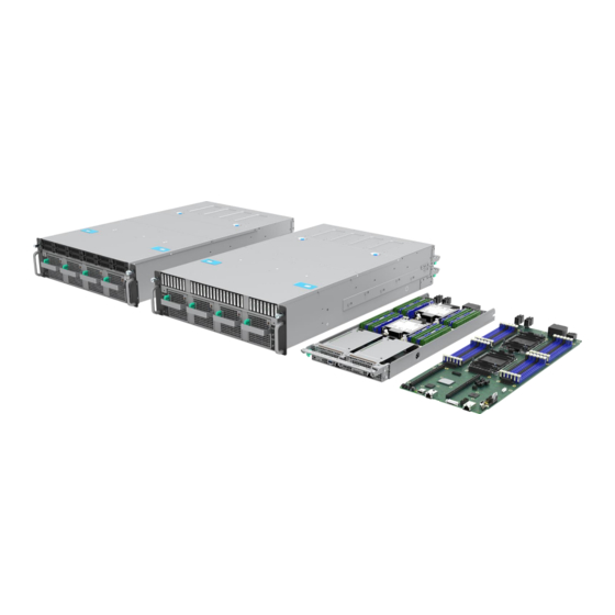
Intel® Server D40AMP
Family
Intel® Server Board D40AMP
Intel® Compute Module D40AMP
Intel® Server System D40AMP
Integration and Service Guide
A guide providing instructions for the installation and
removal of system components and spares.
Rev. 1.2
June 2022
Delivering Breakthrough Data Center System Innovation – Experience What's Inside!
Advertisement
Table of Contents

Related Manuals for Intel D40AMP Series


Summary of Contents for Intel D40AMP Series
- Page 1 Intel® Server D40AMP Family Intel® Server Board D40AMP Intel® Compute Module D40AMP Intel® Server System D40AMP Integration and Service Guide A guide providing instructions for the installation and removal of system components and spares. Rev. 1.2 June 2022 Delivering Breakthrough Data Center System Innovation – Experience What’s Inside!
- Page 2 <Blank page>...
- Page 3 Intel® Server D40AMP Family Integration and Service Guide Document Revision History Date Revision Changes November 2021 Initial release. • Updated URL in chapter 1. March 2022 • Modified assembly procedure in 2.2.1 and 2.2.2. • Changed SSD insertion procedure in 3.6.3 according to factory recommendations.
- Page 4 You may not use or facilitate the use of this document in connection with any infringement or other legal analysis concerning Intel products described herein. You agree to grant Intel a non-exclusive, royalty-free license to any patent claim thereafter drafted which includes subject matter disclosed herein.
- Page 5 Intel recommends that the following steps be taken when performing any procedures described within this document or while performing service to any computer system.
- Page 6 Caution: Slide/rail mounted equipment is not to be used as a shelf or a work space. Intel warranties that this product will perform to its published specifications. However, all computer systems are inherently subject to unpredictable system behavior under various environmental and other conditions.
- Page 7 Note: This requirement applies only to Intel® server system products released in 2019 or later. Legacy Intel® server system products (released in 2018 or earlier) provide safeguards that require no additional access restrictions.
-
Page 8: Table Of Contents
Intel® Server D40AMP Family Integration and Service Guide Table of Contents 1. Introduction ................................14 2. System Features Overview ............................. 15 System Components Identification ........................15 Compute Module Components ..........................20 Server Board Features ..............................21 3. System Components Installation / Removal / Replacement ................22 Installing Chassis into a Rack ............................ - Page 9 EDSFF SSD Extraction and Installation ......................... 57 3.10.1 EDSFF Drive Extraction ..............................57 3.10.2 EDSFF Drive Installation .............................. 57 3.11 Intel® Virtual RAID on CPU (Intel® VROC) Upgrade Key Installation/Removal ........58 3.12 Trusted Platform Module (TPM) Installation/Removal .................. 59 3.12.1 TPM Installation ................................59 3.12.2 TPM Removal ...................................
- Page 10 Figure 10. I/O Breakout Cable Connector Identification ......................20 Figure 11. Compute Module Component Identification ......................21 Figure 12. Intel® Server Board D40AMP1SB Feature Identification ..................21 Figure 13. System Directional Reference ............................22 Figure 14. Rail Kit - Inner Rail Removal ............................24 Figure 15.
- Page 11 Figure 67. EDSFF Drive Extraction ..............................57 Figure 68. EDSFF Drive Installation ..............................57 Figure 69. Intel® VROC Upgrade Key Installation ........................58 Figure 70. Trusted Platform Module (TPM) Installation ......................59 Figure 71. Trusted Platform Module (TPM) Removal......................... 60 Figure 72.
- Page 12 Intel® Server D40AMP Family Integration and Service Guide Figure 82. Power Supply Removal ..............................68 Figure 83. Power Supply Installation ..............................68 Figure 84. System Fan Configuration ............................... 69 Figure 85. 80mm System Fan Removal ............................69 Figure 86. 80mm System Fan Installation ............................70 Figure 87.
- Page 13 Intel® Server D40AMP Family Integration and Service Guide Figure 124. Securing Secondary PDB ............................... 94 Figure 125. Connecting Cables to Secondary PDB ........................94 Figure 126. Removing Screws Securing Drive Cage ........................95 Figure 127. Removing Drive Cage ..............................96 Figure 128.
-
Page 14: Introduction
Appendix A – Getting Help. Lists server system support and contact information. Appendix B – Multilingual Safety Information. Includes safety instructions in eight languages. Appendix C – Intel® Server D40AMP Family Collateral List. Provides a list of documents relevant to the Intel Server D40AMP Family. -
Page 15: System Features Overview
Intel® Server D40AMP Family Integration and Service Guide System Features Overview This chapter provides a reference to identify and locate the features associated with the Intel® Server D40AMP Family. System Components Identification All systems within the Intel® Server D40AMP Family are designed for loading compute modules from the back and loading hot-swappable storage devices from the front. -
Page 16: Figure 3. Storage Drive Bays Identification - Systems Configured With Chassis Vp3U2Hac21W0
Intel® Server D40AMP Family Integration and Service Guide Figure 3. Storage Drive Bays Identification – Systems Configured with Chassis VP3U2HAC21W0 Figure 4. Front Components Identification – Systems Configured with Chassis VP3E1HAC21W0... -
Page 17: Figure 5. Chassis Front Panel Features
Intel® Server D40AMP Family Integration and Service Guide The chassis includes two front control panels, connected to each of the compute modules, in the same layout they are installed. The following figure identifies the features of the control panel for modules 1 and Figure 5. -
Page 18: Figure 6. Server Chassis Component Identification - Vp3U2Hac21W0 Chassis
Intel® Server D40AMP Family Integration and Service Guide Figure 6. Server Chassis Component Identification – VP3U2HAC21W0 Chassis... -
Page 19: Figure 7. Server Chassis Component Identification - Vp3E1Hac21W0
Intel® Server D40AMP Family Integration and Service Guide Figure 7. Server Chassis Component Identification – VP3E1HAC21W0... -
Page 20: Compute Module Components
Intel® Server D40AMP Family Integration and Service Guide Compute Module Components Figure 8. 1U Compute Module External I/O Feature Identification Figure 9. Compute Module Control Panel Features Figure 10. I/O Breakout Cable Connector Identification... -
Page 21: Server Board Features
Server Board Features The following figure provides a general overview of the physical server board, identifying key feature and component locations. Refer to the Intel® Server D40AMP Family Technical Product Specification for details. Figure 12. Intel® Server Board D40AMP1SB Feature Identification... -
Page 22: System Components Installation / Removal / Replacement
Intel® Server D40AMP Family Integration and Service Guide System Components Installation / Removal / Replacement This chapter provides instructions for the installation and removal of system components and other Intel accessories. Before You Begin Before integration of any system components, review all safety and ESD precautions found in the Safety Warnings section at the beginning of this document. -
Page 23: Installing Chassis Into A Rack
Intel® Server D40AMP Family Integration and Service Guide Installing Chassis into a Rack The Intel® Server D40AMP includes a rail kit for system installation into a 4-post rack or cabinet. The following installation guidelines should be observed. • For proper system ventilation, leave a minimum of 15 cm clearance in the front and rear of the system. -
Page 24: Installing Rail Kit
Intel® Server D40AMP Family Integration and Service Guide 3.1.1 Installing Rail Kit Installing the rails: Remove the Inner Rail from the Right and Left rail assemblies. Figure 14. Rail Kit - Inner Rail Removal 1. Slide out the inner rail until it clicks (see Letter A). -
Page 25: Figure 16. Rail Kit - Attaching Inner Rail To Chassis
Intel® Server D40AMP Family Integration and Service Guide Figure 16. Rail Kit – Attaching Inner Rail to Chassis 6. Install the (L)eft and (R)ight inner rail segments to the appropriate sides of the server: • Align six key holes of the inner rail segment to the matching mounting studs on the side of the chassis. -
Page 26: Figure 17. Rail Kit - Installing Rail To Mounting Posts
Intel® Server D40AMP Family Integration and Service Guide Figure 17. Rail Kit - Installing Rail to Mounting Posts 8. Install the rails one at a time to the back and front posts of the rack or cabinet: • Position the rear bracket along the outside of the rear post and push the pins into the post from the back (see Letters A and B). -
Page 27: Installing Chassis Into Rack
Intel® Server D40AMP Family Integration and Service Guide 3.1.2 Installing Chassis into Rack Important Safety Note: Due to the weight of a fully configured system, Intel recommends: • Remove all installed modules and power supplies from the system before attempting to install the system into a rack. -
Page 28: Securing System To Rack
Intel® Server D40AMP Family Integration and Service Guide 3.1.3 Securing System to Rack Figure 19. Securing Chassis in Rack Slide the system into a rack (see Letter A) and secure it using the thumbscrews on the handles (see Letter B). -
Page 29: Chassis Cover Installation / Removal
Intel® Server D40AMP Family Integration and Service Guide Chassis Cover Installation / Removal Required Tools and Supplies: • Phillips* #2 screwdriver 3.2.1 Chassis Front Cover Removal Figure 21. Removing Front Cover Screws 1. Using screwdriver remove two screws on both sides of the front cover. -
Page 30: Chassis Front Cover Installation
Intel® Server D40AMP Family Integration and Service Guide 3.2.2 Chassis Front Cover Installation Front Cover Screws Installation Chassis Front Cover Installation Figure 23. Installing Front Cover 1. Install the chassis front cover by sliding it towards the back of the chassis as shown in the previous figure. -
Page 31: Chassis Back Cover Removal
Intel® Server D40AMP Family Integration and Service Guide 3.2.3 Chassis Back Cover Removal Figure 24. Removing Back Cover Screws 1. Remove two screws on both sides of the back cover. Figure 25. Removing Chassis Back Cover 2. Press and rotate the fasteners 90 degrees counterclockwise (see Letter A) and lift the back cover away... -
Page 32: Chassis Back Cover Installation
Intel® Server D40AMP Family Integration and Service Guide 3.2.4 Chassis Back Cover Installation Figure 26. Installing Chassis Back Cover 1. Install the chassis back cover by sliding it towards the front in a tilted manner (see Letter A). 2. Secure the chassis back cover by pushing and twisting the fasteners 90 degrees clockwise. -
Page 33: Compute Module Removal / Installation
Intel® Server D40AMP Family Integration and Service Guide Compute Module Removal / Installation Required Tools and Supplies: • Anti-static wrist strap and conductive workbench pad (recommended) 3.3.1 Compute Module Removal 1. Power down the module using the corresponding power button on the chassis front panel or on the control panel of the module to be removed. -
Page 34: Compute Module Installation
Intel® Server D40AMP Family Integration and Service Guide 3.3.2 Compute Module Installation Figure 29. Installing Compute Module 1. Ensure the lever at the front of the module is lowered. If not, press the green latch inward and lower the lever. -
Page 35: Air Duct Removal / Installation
Intel® Server D40AMP Family Integration and Service Guide Air Duct Removal / Installation To maintain system thermals, the air duct must always be in place when the system is operational. Removal of the air duct is necessary when installing or removing CPU or memory. -
Page 36: Processor Installation / Removal
Processor Installation / Removal The Intel® Server D40AMP Family designed for 1U height heat sinks as shown in the following figures. There are two types of 1U heat sinks – front heat sink and back heat sink. The front heat sink is used for CPU0, and the back heat sink is used for CPU1. -
Page 37: Processor Heat Sink Module (Phm) Assembly
ESD Gloves (recommended) • T-30 Torx* screwdriver Required Components: • Gen Intel® Xeon® Scalable processor in a shipping tray • Processor carrier clip • Processor heat sink with thermal interface material (TIM) pad To properly assemble the PHM and install it onto the server board, the procedures described in the next sections must be followed in the order specified. -
Page 38: Figure 35. Installing Processor Carrier Clip Onto Processor - Part 1
Intel® Server D40AMP Family Integration and Service Guide Figure 35. Installing Processor Carrier Clip onto Processor – Part 1 Figure 36. Installing Processor Carrier Clip onto Processor – Part 2 1. With the processor still in its tray, place the processor carrier clip over the processor. -
Page 39: Figure 37. Handling Heat Sink
Intel® Server D40AMP Family Integration and Service Guide Figure 37. Handling Heat Sink 6. Remove the plastic protective film from the Thermal Interface Material (TIM) pad. Figure 38. Pin 1 Indicator of Processor Carrier Clip 7. Holding the heat sink with its TIM side facing the processor, align the corner cut-out on the heat sink with the Pin 1 indicator of the processor carrier clip. -
Page 40: Phm Installation
Intel® Server D40AMP Family Integration and Service Guide 3.5.2 PHM Installation Figure 39. Socket Protective Cover Removal 1. If present, remove the CPU socket protective cover by squeezing the finger grips (see Letter A) and pulling the cover up (see Letter B). -
Page 41: Figure 41. Phm Installation Onto Server Board
7. Tighten the heat sink nuts using a T30 Torx* screwdriver to 8 in-lb. There is no specific sequence needed for tightening. Note: Intel strongly recommends that both processors are installed. If only one processor is installed, do not install a processor heat sink on an empty socket. -
Page 42: Processor Heat Sink Module (Phm) Removal
Intel® Server D40AMP Family Integration and Service Guide 3.5.3 Processor Heat Sink Module (PHM) Removal Required Tools and Supplies: • Anti-static wrist strap and conductive workbench pad (recommended) • ESD Gloves (recommended) • T-30 Torx* screwdriver Figure 43. PHM Assembly Removal from Processor Socket 1. -
Page 43: Phm Disassembly
Intel® Server D40AMP Family Integration and Service Guide 6. If not replacing the processor, reinstall the socket cover. Figure 44. Reinstall Socket Cover • Squeeze the finger grips at each end of the cover (see Letter A) • Carefully lower the cover over the four alignment pins of the bolster plate and onto the processor socket (see Letter B). -
Page 44: Figure 46. Processor Carrier Clip Removal From Phm Assembly
Intel® Server D40AMP Family Integration and Service Guide Figure 46. Processor Carrier Clip Removal from PHM Assembly 4. Return the lever to the original position (see Letter C). 5. Unlatch the tab on each corner of the processor carrier clip and lift the clip up from the heat sink (see... -
Page 45: Memory Module (Dimm) Removal / Installation
The Intel® Server Board D40AMP supports standard SDRAM DDR4 RDIMMs, LDRIMMs, and Intel® Optane™ persistent memory 200 series modules (also known as Intel® Optane™ PMem). SDRAM DDR4 DIMM and Intel® Optane™ PMem module will be commonly referred to as “memory module” in the following instructions. -
Page 46: Memory Module Removal
Intel® Server D40AMP Family Integration and Service Guide 3.6.2 Memory Module Removal Figure 48. Memory Module Removal 1. Identify and locate the memory module or DIMM blank to be removed. 2. Open the ejection tabs at both ends of the selected memory slot (see Letter A). The memory module will slightly lift from the slot. -
Page 47: Pcie* Add-In Card Removal / Installation
PCIe* Add-In Card Removal / Installation The Intel® Compute Module D40AMP includes two riser assemblies that support one low-profile PCIe* add- in card each, for a total of up to two add-in cards. The following figure shows the riser card assembly features. -
Page 48: Riser Assembly Installation
Intel® Server D40AMP Family Integration and Service Guide 3.7.2 Riser Assembly Installation Figure 51. Riser Assembly Installation 1. Align the riser card edge connector to the riser slot on the server board (see Letter A). 2. Carefully push down on the riser assembly until the riser card is securely seated in the riser slot. -
Page 49: Pcie* Add-In Card Installation
Intel® Server D40AMP Family Integration and Service Guide 3.7.3 PCIe* Add-In Card Installation 1. Remove the selected riser assembly from the module (see Section 3.7.1). Figure 52. Add-In Card Installation 2. Remove the rear filler plate from the metal frame of the riser assembly (see Letter A). -
Page 50: M.2 Ssd Removal / Installation
Intel® Server D40AMP Family Integration and Service Guide M.2 SSD Removal / Installation Before following the procedures in this section, remove the selected module from the server chassis (see Section 3.3.1) and then remove the selected riser assembly from the module (see Section 3.7.1). -
Page 51: M.2 Ssd Installation
Intel® Server D40AMP Family Integration and Service Guide 3.8.3 M.2 SSD Installation Figure 56. M.2 SSD Installation 1. If present, remove the screw from the M.2 mounting standoff on the left side of the riser assembly. 2. Align the notch within the SSD edge connector with the key in the M.2 connector and insert the SSD into the connector (see Letter A). -
Page 52: Ssd Drive Removal, Assembly, And Installation - Chassis Vp3U2Hac21W0 Only
Intel® Server D40AMP Family Integration and Service Guide U.2 SSD Drive Removal, Assembly, and Installation – Chassis VP3U2HAC21W0 Only Systems configured with chassis VP3U2HAC21W0 support up to twenty four 2.5” U.2 NVMe* SSD Drives. Each drive is installed into a tool-less drive carrier. This section provides instructions for drive extraction from the chassis, drive assembly, and drive installation into the chassis. -
Page 53: Accessing Drive Bays For Modules 3 And 4
Intel® Server D40AMP Family Integration and Service Guide Required Tools and Supplies: • Anti-static wrist strap and conductive workbench pad (recommended) 3.9.1 Accessing Drive Bays for Modules 3 and 4 The following steps are required to access the hot-swap drive bays for modules 3 and 4. -
Page 54: 2.5" Ssd Drive Assembly For 7-Mm Drives
2.5” SSD Drive Assembly for 7-mm Drives The Intel® Server D40AMP Family supports 2.5” U.2 SSDs with 7 mm of thickness when used in conjunction with the supplied blanks. The supplied blank for 2.5” bays has two parts: top and bottom. The top part must be attached to the 7-mm drive to fit properly inside the 2.5”... -
Page 55: 2.5" Ssd Drive / Drive Blank Removal
Intel® Server D40AMP Family Integration and Service Guide 3.9.3 2.5” SSD Drive / Drive Blank Removal The 2.5” drive mounting rails in the system are not removable. They slide out so that the storage drives can be installed or removed. When sliding out a drive mounting rail from the system, only pull it as much as it allows without forcing it. -
Page 56: Figure 66. 2.5" 15-Mm Drive Installation Into 2.5" Drive Bay
3. Insert the drive/drive assembly into the drive bay (see Letter A). Note: Intel recommends holding the drive with one hand while holding the lever with the other hand. 4. Slide the drive/drive assembly forward until the connector is fully engaged with the backplane (see Letter... -
Page 57: 3.10 Edsff Ssd Extraction And Installation
Intel® Server D40AMP Family Integration and Service Guide 3.10 EDSFF SSD Extraction and Installation Systems configured with chassis VP3E1HAC21W0 support up to 32 hot-swappable, full-length (E1.L) PCIe* Enterprise and Data Center SSD Form Factor (EDSFF) NVMe* drives. This section provides instructions for EDSFF drive extraction from the chassis and drive installation into the chassis. -
Page 58: 3.11 Intel® Virtual Raid On Cpu (Intel® Vroc) Upgrade Key Installation/Removal
5. Place the key over the connector and confirm that the orientation of the key matches that of the connector. 6. Press the key down onto the connector. 7. Removal of the Intel® VROC Upgrade Key must be done by pulling it out of the board using the attached loop. -
Page 59: 3.12 Trusted Platform Module (Tpm) Installation/Removal
Intel® Server D40AMP Family Integration and Service Guide 3.12 Trusted Platform Module (TPM) Installation/Removal This section provides instructions to install a Trusted Platform Module (TPM) in the system. Refer to the Intel® Server D40AMP Family Configuration Guide for TPM available options. Required Tools and Supplies •... -
Page 60: Tpm Removal
Intel® Server D40AMP Family Integration and Service Guide 3.12.2 TPM Removal 1. Remove the compute module from the chassis (see Section 3.3.1). 2. Remove riser card assembly #2 (see Section 3.7.1). Figure 71. Trusted Platform Module (TPM) Removal 3. Locate the TPM connector on the server board. -
Page 61: 3.13 System Battery Replacement
Intel® Server D40AMP Family Integration and Service Guide 3.13 System Battery Replacement Required Tools and Supplies: • Anti-static wrist strap and conductive workbench pad (recommended) 3.13.1 System Battery Removal Figure 72. System Battery Removal 1. Remove the selected module from the server chassis (see Section 3.3.1) -
Page 62: 3.14 Server Board Replacement
2. Remove the air duct (see Section 3.4.1). 3. Remove riser card assemblies (see Section 3.7.1). 4. Remove all options installed onto the server board including (if installed) the Intel® VROC 7.5 key (see Section 3.11) and TPM module (see Section 3.12.2). -
Page 63: Figure 75. Removing Vr Heat Sink Screws
Intel® Server D40AMP Family Integration and Service Guide Figure 75. Removing VR Heat Sink Screws 8. Remove 14 screws securing the voltage regulators (VR) heat sinks (see Letter B) Figure 76. Removing Chipset and Ethernet ICs Heat Sink Screws 9. Remove 4 spring-loaded screws securing the chipset and Ethernet controller ICs heat sinks to the... -
Page 64: Figure 77. Server Board Removal
Intel® Server D40AMP Family Integration and Service Guide Figure 77. Server Board Removal 10. Slide the server board slightly towards the back of the module tray to disengage the edge connectors from the cut-outs in the module tray. Then, carefully lift the server board from the module tray (see... -
Page 65: Server Board Installation
Intel® Server D40AMP Family Integration and Service Guide 3.14.2 Server Board Installation Figure 78. Server Board Installation 1. Remove the new server board from its anti-static bag. 2. Carefully lower the server board into the module tray. 3. Slide the server board slightly toward the front of the module tray until the connectors go through the cut-out in the front panel and the screw holes in the server board align with the standoffs in the module tray (see Letter A). -
Page 66: Figure 79. Securing Server Board With Screws
Intel® Server D40AMP Family Integration and Service Guide Figure 79. Securing Server Board with Screws 4. Fasten the server board to the module tray with 7 previously removed screws (see Letter B). Tighten to 5 in-lb. Figure 80. Installing VR Heat Sinks 5. -
Page 67: Figure 81. Installing Chipset And Ethernet Ics Heat Sinks
7. Reinstall processors (see Section 3.5.2). 8. Reinstall DIMMs (see Section 3.6.1). 9. Reinstall all options previously removed from the server board, including the Intel® VROC 7.5 key (see Section 3.11) and TPM module (see Section 3.12.1). 10. Reinstall the riser card assemblies (see Section 3.7.2). -
Page 68: 3.15 Power Supply Replacement
Intel® Server D40AMP Family Integration and Service Guide 3.15 Power Supply Replacement Required Tools and Supplies: • Anti-static wrist strap and conductive workbench pad (recommended) Figure 82. Power Supply Removal 1. Identify the power supply to be replaced. 2. Detach the power cord from the power supply to be removed. -
Page 69: 3.16 System Fan Replacement
3.16 System Fan Replacement The Intel® Server D40AMP Family includes four 80mm fans at the front of the chassis, and six 40mm fans located in the back of the chassis for a total of 10 dual rotor system fans. This section provides instructions to replace both the 80mm and 40mm system fans. -
Page 70: Replacing 40Mm System Fans
Intel® Server D40AMP Family Integration and Service Guide Figure 86. 80mm System Fan Installation 2. Insert the system fan assembly into the open fan assembly bay (see Letter A) and push it until it locks into place. 3.16.2 Replacing 40mm System Fans Caution: System fans operate at very high speeds. -
Page 71: Figure 87. 40Mm System Fan Removal
Intel® Server D40AMP Family Integration and Service Guide Figure 87. 40mm System Fan Removal Grasp the faulty system fan on both green marked ends (see Letter A) and pull it up and away from the chassis (see Letter B). This also disconnects the fan cable from the onboard 8-pin fan connector. -
Page 72: 3.17 U.2 Backplane Replacement - Chassis Vp3U2Hac21W0
Intel® Server D40AMP Family Integration and Service Guide 3.17 U.2 Backplane Replacement – Chassis VP3U2HAC21W0 Systems configured with chassis VP3U2HAC21W0 include two backplanes supporting up to twelve U.2 NVMe* SSDs each. This section provides instructions to replace them. Once the backplane to be replaced has been accessed, the replacement steps are the same for either. -
Page 73: Figure 90. Removing Backplane Screws
Intel® Server D40AMP Family Integration and Service Guide Figure 90. Removing Backplane Screws 6. Remove the screws securing the backplane to the drive bay (see Letter D). Figure 91. Removing Backplane 7. Tilt the backplane (see Letter F) to detach it from the studs in the upper part (see Letter E) and remove it. -
Page 74: U.2 Backplane Installation
Intel® Server D40AMP Family Integration and Service Guide 3.17.2 U.2 Backplane Installation Figure 92. Backplane Installation 1. Remove the new backplane from its packaging. Lower the backplane into the chassis in a tilted manner and attach it to the studs (see Letter B) by bringing it to vertical position (see Letter A). -
Page 75: Figure 94. Connecting Cables To Backplane
Intel® Server D40AMP Family Integration and Service Guide Figure 94. Connecting Cables to Backplane 3. Connect all previously disconnected cables to the backplane, including data cables (see Letter A), power cable (see Letter B), and I C cable (see Letter C). -
Page 76: 3.18 Power Distribution Boards Replacement
Intel® Server D40AMP Family Integration and Service Guide 3.18 Power Distribution Boards Replacement The Intel® Server D40AMP Family includes two power distribution boards (PDBs) providing power and management connections for several components in the system. The following sections provide instructions to replace both PDBs. -
Page 77: Rear Drive Bay Assembly Removal
Intel® Server D40AMP Family Integration and Service Guide Figure 96. Fan Wall Bracket Removal 9. Remove two #6-32 screws on each side of the chassis and one 3mm screw in the middle of the 40mm fan wall bracket (see Letter A). -
Page 78: Figure 98. Removing Rear Drive Bay Spring Mechanism Screws
Intel® Server D40AMP Family Integration and Service Guide Figure 98. Removing Rear Drive Bay Spring Mechanism Screws 3. Remove eight screws from the chassis sides (see Letter A) and six screws from the inner part of the chassis (see Letter B) to release the drive bay spring mechanism attached to the drive bay. -
Page 79: Front Drive Bay Assembly Removal
Intel® Server D40AMP Family Integration and Service Guide 3.18.3 Front Drive Bay Assembly Removal. Figure 100. Front Drive Bay Screws Removal 1. Remove four screws from the top part of the chassis sides, and two screws from behind the chassis rack... -
Page 80: Figure 101. Open Cable Clips
Intel® Server D40AMP Family Integration and Service Guide Figure 101. Open Cable Clips 2. Open three plastic cable clips attaching cables to the chassis. 3. Remove four pan-head screws attaching cable covers to the chassis. 4. Slide cable covers to the back to disengage them from the studs and remove them from the chassis. -
Page 81: Power Bus Bars And Primary Pdb Removal
Intel® Server D40AMP Family Integration and Service Guide 3.18.4 Power Bus Bars and Primary PDB Removal Figure 103. Bus Bars Screws Removal 1. Using Torx T-10 screwdriver remove the screws securing the bus bars to the primary and secondary PDBs. -
Page 82: Figure 105. Disconnecting Cables From Primary Pdb
Intel® Server D40AMP Family Integration and Service Guide Figure 105. Disconnecting Cables from Primary PDB 3. Remove the sideband cable (see Letter A) and the power cable (see Letter B) from the primary PDB. -
Page 83: Figure 106. Primary Pdb Screws Removal
Intel® Server D40AMP Family Integration and Service Guide Figure 106. Primary PDB Screws Removal 4. Remove six screws securing primary PDB to the chassis. 5. Lift the primary PDB slightly to disengage it from the studs Figure 107. Primary PDB Removal 6. -
Page 84: Primary Pdb And Power Bus Bars Installation
Intel® Server D40AMP Family Integration and Service Guide 3.18.5 Primary PDB and Power Bus Bars Installation Figure 108. Primary PDB Installation 1. Remove the new PDB from its packaging. Install it by sliding it into the chassis in a tilted manner (see Letter A) and then lower it down into the chassis (see Letter B). -
Page 85: Figure 110. Connecting Cables To Primary Pdb
Intel® Server D40AMP Family Integration and Service Guide Figure 110. Connecting Cables to Primary PDB 3. Connect the sideband cable (see Letter A) and the power cable (see Letter B). Figure 111. Bus Bars Installation 4. Install the bus bars by lowering them vertically into place (see Letter A). -
Page 86: Front Drive Bay Assembly Installation
Intel® Server D40AMP Family Integration and Service Guide Figure 112. Securing Bus Bars to PDBs 5. Align the screw holes in the bus bars with those of the primary and secondary PDBs as shown in the previous figure and secure them with the previously removed screws. Tighten them to 8 lb-in. -
Page 87: Figure 114. Securing Front Drive Bay Assembly
Intel® Server D40AMP Family Integration and Service Guide Figure 114. Securing Front Drive Bay Assembly 3. Secure the front drive bay assembly to the chassis with four screws on the sides of the chassis and two behind the chassis rack handles as shown in the previous figure. -
Page 88: Rear Drive Bay Assembly Installation
Intel® Server D40AMP Family Integration and Service Guide 3.18.7 Rear Drive Bay Assembly Installation Figure 116. Rear Drive Bay Assembly Installation 1. Install the rear drive bay assembly by vertically lowering it into the chassis and aligning with the appropriate holes in the chassis sides and inner part (see Letter A). -
Page 89: Figure 118. Connecting Cables To Backplanes
Intel® Server D40AMP Family Integration and Service Guide Figure 118. Connecting Cables to Backplanes 3. Reconnect to each backplane the previously removed cables including data cables (see Letter A), power cable (see Letter B), and I C cable (see Letter C). - Page 90 Intel® Server D40AMP Family Integration and Service Guide 5. Secure it in place with two #6-32 screws on each side of the chassis with torque of 8 lb-in and one 3mm screw in the middle of the fan wall bracket with torque of 5 lb-in (see Letter C).
-
Page 91: Replacing Secondary Power Distribution Board - Chassis Vp3U2Hac21W0
Intel® Server D40AMP Family Integration and Service Guide 3.18.8 Replacing Secondary Power Distribution Board – Chassis VP3U2HAC21W0 Required Tools and Supplies: • Phillips* head screwdriver #2 • T-10 Torx* screwdriver • Anti-static wrist strap and conductive workbench pad (recommended) 1. Follow the procedures explained starting in... -
Page 92: Figure 121. Removing Screws From Secondary Pdb
Intel® Server D40AMP Family Integration and Service Guide Figure 121. Removing Screws from Secondary PDB 3. Remove six pan-head screws securing secondary PDB to the bottom of the chassis (see Letter A). 4. Remove two 3mm flat-head screws securing secondary PDB to two tabs on the top chassis tray (see Letter B). -
Page 93: Figure 123. Secondary Pdb Installation
Intel® Server D40AMP Family Integration and Service Guide 7. Remove the new PDB from its packaging. Figure 123. Secondary PDB Installation 8. Tilt the secondary PDB slightly backwards and lower it into the chassis (see Letter A). Be careful not to damage the data cables from the ExaMAX* connectors. -
Page 94: Figure 124. Securing Secondary Pdb
Intel® Server D40AMP Family Integration and Service Guide Figure 124. Securing Secondary PDB 10. Secure the secondary PDB to the chassis using six pan-head screws (see Letter B) and two 3mm flat-head screws (see Letter C) with torque of 5 lb-in. -
Page 95: Figure 126. Removing Screws Securing Drive Cage
Intel® Server D40AMP Family Integration and Service Guide 3.19 Midplane Replacement – Chassis VP3E1HAC21W0 Required Tools and Supplies: • Phillips* head screwdriver #2 • Anti-static wrist strap and conductive workbench pad (recommended) 1. Power down all compute modules 2. Disconnect all external cables from the chassis. -
Page 96: Figure 127. Removing Drive Cage
Intel® Server D40AMP Family Integration and Service Guide Figure 127. Removing Drive Cage 8. Remove the drive cage by sliding it towards the front of the chassis Figure 128. Fan Wall Bracket Removal 9. Remove two #6-32 screws on each side of the chassis and one 3mm screw in the middle of the 40mm fan wall bracket (see Letter A). -
Page 97: Figure 129. Unplugging Cable Connectors
Intel® Server D40AMP Family Integration and Service Guide Figure 129. Unplugging Cable Connectors 13. Unplug all connectors from the midplane and the primary PDB including sixteen data cable connectors (see Letter A), four power cable connectors (see Letter B), sideband cable connector (see Letter C), and I cable connector (see Letter D). -
Page 98: Figure 131. Midplane Removal
Intel® Server D40AMP Family Integration and Service Guide 15. Remove ten screws including eight screws securing the midplane and two screws securing the cable clamp holders to the midplane. Figure 131. Midplane Removal 16. Remove the midplane from the chassis by lifting it vertically. -
Page 99: Figure 132. Midplane Installation
Intel® Server D40AMP Family Integration and Service Guide Figure 132. Midplane Installation 17. Unpack the new midplane and position it in the chassis to align with the mounting holes... -
Page 100: Figure 133. Cable Clamp Holders Installation
Intel® Server D40AMP Family Integration and Service Guide Figure 133. Cable Clamp Holders Installation 18. Install cable clamp holders and secure them with the screws Figure 134. Securing Midplane 19. Secure the midplane by tightening ten screws to 5 lb-in. -
Page 101: Figure 135. Reconnecting Cable Connectors
Intel® Server D40AMP Family Integration and Service Guide 20. Tie the data cables with the cable clamps Figure 135. Reconnecting Cable Connectors 21. Reconnect all cable connectors to the midplane and the primary PDB including sixteen data cable connectors (see Letter A), four power cable connectors (see Letter B), sideband cable connector (see Letter C), and I C cable connector (see Letter D). -
Page 102: Figure 136. Securing Fan Wall Bracket
Intel® Server D40AMP Family Integration and Service Guide Figure 136. Securing Fan Wall Bracket 22. Lower the 40mm fan wall bracket into the chassis (see Letter A) and slide it towards the back of the chassis to engage it with four studs at the bottom (see Letter B). -
Page 103: Figure 138. Securing Drive Cage
Intel® Server D40AMP Family Integration and Service Guide Figure 138. Securing Drive Cage 26. Secure the drive cage with six screws tightened to 8 lb-in (see Letter B). 27. Reinstall the rear cover (see Section 3.2.4). 28. Reinstall all EDSFF SSDs and blanks (see Section 3.10.2). -
Page 104: System Packaging Assembly Instructions
Intel® Server D40AMP Family Integration and Service Guide System Packaging Assembly Instructions The original Intel packaging is designed to provide protection to a fully configured system and has been tested to meet ISTA (International Safe Transit Association) Test Procedure 3A (2008). The packaging is designed to be re-used. - Page 105 Intel® Server D40AMP Family Integration and Service Guide 2. Put the red ESD foam in the front of the system aligned to the drive bays. Wrap the system with the red foam sheet. 3. Carefully lower the system into the inner shipping box as shown in the following image.
- Page 106 Intel® Server D40AMP Family Integration and Service Guide 4. Put the top front foam and top rear foam on. Follow the next image. 5. Place the accessory box and Rail Kit in as shown in the following image.
- Page 107 Intel® Server D40AMP Family Integration and Service Guide 6. Fold the top flaps of the inner box closed, short flaps first, followed by long flaps. Note: By design, the two side flaps do not meet. Do not tape the side flaps shut.
-
Page 108: Appendix A. Getting Help
Intel cbwarranty Configure to Order tool. If a solution cannot be found at Intel’s support site, submit a service request via Intel’s online service center at https://supporttickets.intel.com/servicecenter?lang=en-US. In addition, you can also view previous support requests. (Login required to access previous support requests) Contact an Intel support representative using one of the support phone numbers available at https://www.intel.com/content/www/us/en/support/contact-support.html... -
Page 109: Appendix B. Product Safety - Multi-Language
Intel® Server D40AMP Family Integration and Service Guide Appendix B. Product Safety – Multi-Language WARNING: English (US) The power supply in this product contains no user-serviceable parts. There may be more than one supply in this product. Refer servicing only to qualified personnel. - Page 110 Intel® Server D40AMP Family Integration and Service Guide For proper cooling and airflow, always reinstall the chassis covers before turning on the system. Operating the system without the covers in place can damage system parts. To install the covers: • Check first to make sure you have not let loose tools or parts inside the system.
- Page 111 Intel® Server D40AMP Family Integration and Service Guide ОСТОРОЖНО: русский Блок питания данного изделия не содержит деталей, подлежащих обслуживанию пользователем. В этом изделии может быть несколько блоков питания. Обслуживание должно выполняться только квалифицированным персоналом. Не модифицируйте и не используйте прилагаемый кабель питания, если он не...
- Page 112 Intel® Server D40AMP Family Integration and Service Guide ОСТОРОЖНО: русский (продолжение) Для обеспечения надлежащего охлаждения и воздушного потока всегда устанавливайте на место крышки корпуса перед включением системы. Работа системы без установленных крышек может привести к повреждению компонентов системы. Чтобы установить крышки, выполните следующие действия: Сначала...
- Page 113 Intel® Server D40AMP Family Integration and Service Guide УВАГА! Українська Джерело живлення в цьому виробі не містить жодних частин, які користувачі могли б обслуговувати самостійно. Цей виріб може містити більше одного джерела живлення. Обслуговувати його може виключно кваліфікований персонал. Не намагайтеся модифікувати шнур живлення змінного струму з комплекту або...
- Page 114 Intel® Server D40AMP Family Integration and Service Guide УВАГА! Українська (продовження) Для правильного охолодження та вентиляції завжди повертайте на місце кришки корпусу перед увімкненням системи. Робота системи без кришок може пошкодити деталі системи. Щоб установити кришки, виконайте такі дії: Спочатку переконайтеся, що всередині системи не залишилося деталей або...
- Page 115 Intel® Server D40AMP Family Integration and Service Guide AVERTISSEMENT: Français Le bloc d'alimentation de ce produit ne contient aucune pièce pouvant être réparée par l'utilisateur. Ce produit peut contenir plus d'un bloc d'alimentation. Veuillez contacter un technicien qualifié en cas de problème.
- Page 116 Intel® Server D40AMP Family Integration and Service Guide Afin de permettre le refroidissement et l’aération du système, réinstallez toujours les panneaux du boîtier avant de mettre le système sous tension. Le fonctionnement du système en l’absence des panneaux risque d’endommager ses pièces. Pour installer les panneaux, procédez comme suit:...
- Page 117 Intel® Server D40AMP Family Integration and Service Guide WARNUNG: Deutsch Benutzer können am Netzgerät dieses Produkts keine Reparaturen vornehmen. Das Produkt enthält möglicherweise mehrere Netzgeräte. Wartungsarbeiten müssen von qualifizierten Technikern ausgeführt werden. Versuchen Sie nicht, das mitgelieferte Netzkabel zu ändern oder zu verwenden, wenn es sich nicht genau um den erforderlichen Typ handelt.
- Page 118 Intel® Server D40AMP Family Integration and Service Guide Zur ordnungsgemäßen Kühlung und Lüftung muß die Gehäuseabdeckung immer wieder vor dem Einschalten installiert werden. Ein Betrieb des Systems ohne angebrachte Abdeckung kann Ihrem System oder Teile darin beschädigen. Um die Abdeckung wieder anzubringen: •...
- Page 119 Intel® Server D40AMP Family Integration and Service Guide AVVERTENZA: Italiano Rivolgersi ad un tecnico specializzato per la riparazione dei componenti dell'alimentazione di questo prodotto. È possibile che il prodotto disponga di più fonti di alimentazione. Non modificare o utilizzare il cavo di alimentazione in c.a. fornito dal produttore, se non corrisponde esattamente al tipo richiesto.
- Page 120 Intel® Server D40AMP Family Integration and Service Guide Per il giusto flusso dell’aria e raffreddamento del sistema, rimettere sempre le coperture del telaio prima di riaccendere il sistema. Operare il sistema senza le coperture al loro proprio posto potrebbe danneggiare i componenti del sistema. Per rimettere le coperture del telaio: •...
- Page 121 Intel® Server D40AMP Family Integration and Service Guide ADVERTENCIAS: Español El usuario debe abstenerse de manipular los componentes de la fuente de alimentación de este producto, cuya reparación debe dejarse exclusivamente en manos de personal técnico especializado. Puede que este producto disponga de más de una fuente de alimentación.
- Page 122 Intel® Server D40AMP Family Integration and Service Guide Para obtener un enfriamiento y un flujo de aire adecuados, reinstale siempre las tapas del chasis antes de poner en marcha el sistema. Si pone en funcionamiento el sistema sin las tapas bien colocadas puede dañar los componentes del sistema. Para instalar las tapas: •...
- Page 123 Intel® Server D40AMP Family Integration and Service Guide אזהרה: עברית ל במוצר זה לא מכילה חלקים שניתנים לשירות על ידי משתמש. ייתכן שיש יותר ממקור אספקת חשמל אספקת החשמ .אחד במוצר זה. לקבלת שירות יש לפנות רק אל אנשים המוסמכים לכך...
- Page 124 Intel® Server D40AMP Family Integration and Service Guide לקירור ולזרימת אוויר תקינים, יש תמיד להתקין מחדש את מכסי המעטפת לפני הפעלת המערכת. הפעלת המערכת ללא :המכסים במקומם, עלולה לגרום נזק לחלקי המערכת. להתקנת המכסים • .המערכת יש לבדוק תחילה כדי לוודא שלא נשארו כלים או חלקים רופפים בתוך...
-
Page 125: Appendix C. Additional References
Public Thermal Configuration Tool Intel® Integrated Baseboard Management Controller Web Console Information for the Integrated BMC (Integrated BMC Web Console) User Guide for the Intel® Server Board Public Web Console D50TNP, M50CYP, and D40AMP Families BIOS Firmware External Product Specification (EPS) BIOS technical information for Intel®... - Page 126 Setup information for Intel® Optane™ Intel® Optane™ Persistent Memory Startup Guide Public persistent memory 200 Intel® System Update Package (SUP) for Intel® Server D40AMP Family Latest system software updates: BIOS Intel® System Firmware Update Utility (SYSFWUPDT) – Various Public and Firmware operating system support Intel®...
-
Page 127: Appendix D. Glossary
Intel® Server D40AMP Family Integration and Service Guide Appendix D. Glossary Term Definition Artificial intelligence. One rack unit (1.75 in.) Two rack units (3.5 in.) BIOS Basic input output system; non-volatile firmware Baseboard management controller Chassis Casing containing the server modules and fans/liquid cooling plumbing...
Need help?
Do you have a question about the D40AMP Series and is the answer not in the manual?
Questions and answers