Sign In
Upload
Manuals
Brands
Intel Manuals
Server
D40AMP Series
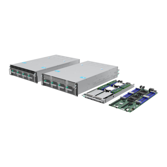
Intel D40AMP Series Manuals
Manuals and User Guides for Intel D40AMP Series. We have
1
Intel D40AMP Series manual available for free PDF download: Integration And Service Manual
Intel D40AMP Series Integration And Service Manual (127 pages)
Brand:
Intel
| Category:
Server
| Size: 15 MB
Table of Contents
Table of Contents
8
Introduction
14
System Features Overview
15
System Components Identification
15
Figure 1. Compute Module Identification - Back View
15
Figure 2. Front Components Identification - Systems Configured with Chassis VP3U2HAC21W0
15
Figure 3. Storage Drive Bays Identification - Systems Configured with Chassis VP3U2HAC21W0
16
Figure 4. Front Components Identification - Systems Configured with Chassis VP3E1HAC21W0
16
Figure 5. Chassis Front Panel Features
17
Figure 6. Server Chassis Component Identification - VP3U2HAC21W0 Chassis
18
Figure 7. Server Chassis Component Identification - VP3E1HAC21W0
19
Compute Module Components
20
Figure 8. 1U Compute Module External I/O Feature Identification
20
Figure 9. Compute Module Control Panel Features
20
Figure 10. I/O Breakout Cable Connector Identification
20
Server Board Features
21
Figure 11. Compute Module Component Identification
21
Figure 12. Intel® Server Board D40AMP1SB Feature Identification
21
System Components Installation / Removal / Replacement
22
Figure 13. System Directional Reference
22
Installing Chassis into a Rack
23
Installing Rail Kit
24
Figure 14. Rail Kit - Inner Rail Removal
24
Figure 15. Rail Kit - Re-Position Middle Rail
24
Figure 16. Rail Kit - Attaching Inner Rail to Chassis
25
Figure 17. Rail Kit - Installing Rail to Mounting Posts
26
Installing Chassis into Rack
27
Figure 18. Installing Chassis into Rack
27
Securing System to Rack
28
Exposing System from Rack
28
Figure 19. Securing Chassis in Rack
28
Figure 20. Exposing Chassis from Rack
28
Chassis Cover Installation / Removal
29
Chassis Front Cover Removal
29
Figure 21. Removing Front Cover Screws
29
Figure 22. Removing Front Cover
29
Chassis Front Cover Installation
30
Figure 23. Installing Front Cover
30
Chassis Back Cover Removal
31
Figure 24. Removing Back Cover Screws
31
Figure 25. Removing Chassis Back Cover
31
Chassis Back Cover Installation
32
Figure 26. Installing Chassis Back Cover
32
Figure 27. Installing Back Cover Screws
32
Compute Module Removal / Installation
33
Compute Module Removal
33
Figure 28. Removing Compute Module
33
Compute Module Installation
34
Figure 29. Installing Compute Module
34
Air Duct Removal / Installation
35
Air Duct Removal
35
Air Duct Installation
35
Figure 30. Removing Air Duct
35
Figure 31. Installing Air Duct
35
Processor Installation / Removal
36
Figure 32. 1U Heat Sinks
36
Figure 33. 1U Heat Sinks Installed in Module
36
Processor Heat Sink Module (PHM) Assembly
37
Figure 34. Processor Components and Processor Socket Reference Diagram
37
Figure 35. Installing Processor Carrier Clip Onto Processor - Part 1
38
Figure 36. Installing Processor Carrier Clip Onto Processor - Part 2
38
Figure 37. Handling Heat Sink
39
Figure 38. Pin 1 Indicator of Processor Carrier Clip
39
PHM Installation
40
Figure 39. Socket Protective Cover Removal
40
Figure 40. PHM Alignment with Socket Assembly
40
Figure 41. PHM Installation Onto Server Board
41
Figure 42. Tighten Heat Sink Nuts
41
Processor Heat Sink Module (PHM) Removal
42
Figure 43. PHM Assembly Removal from Processor Socket
42
PHM Disassembly
43
Figure 44. Reinstall Socket Cover
43
Figure 45. Processor Removal from PHM Assembly
43
Figure 46. Processor Carrier Clip Removal from PHM Assembly
44
Memory Module (DIMM) Removal / Installation
45
Memory Module Installation
45
Figure 47. Memory Module Installation
45
Memory Module Removal
46
Figure 48. Memory Module Removal
46
Pcie* Add-In Card Removal / Installation
47
Riser Assembly Removal
47
Figure 49. Riser Card Assembly
47
Figure 50. Riser Assembly Removal
47
Riser Assembly Installation
48
Figure 51. Riser Assembly Installation
48
Pcie* Add-In Card Installation
49
Pcie* Add-In Card Removal
49
Figure 52. Add-In Card Installation
49
Figure 53. Add-In Card Removal
49
M.2 SSD Removal / Installation
50
M.2 SSD Heat Sink Removal
50
M.2 SSD Heat Sink Installation
50
Figure 54. M.2 Heat Sink Removal
50
Figure 55. M.2 Heat Sink Installation
50
M.2 SSD Installation
51
M.2 SSD Removal
51
Figure 56. M.2 SSD Installation
51
Figure 57. M.2 SSD Removal
51
SSD Drive Removal, Assembly, and Installation - Chassis VP3U2HAC21W0 Only
52
Figure 58. U.2 Hot-Swap Drive Bay Identification
52
Figure 59. 2.5" Drive Bay Components
52
Accessing Drive Bays for Modules 3 and 4
53
Figure 60. Accessing U.2 Hot-Swap Drive Bays for Modules 3 and 4
53
Figure 61. Closing Drive Bays for Modules 3 and 4
53
2.5" SSD Drive Assembly for 7-MM Drives
54
Figure 62. Separating Top and Bottom Parts of Drive Blank
54
Figure 63. Attaching Drive Blank to 7-MM SSD
54
2.5" SSD Drive / Drive Blank Removal
55
2.5" SSD Drive Installation
55
Figure 64. 2.5" Drive Removal
55
Figure 65. 2.5" 7-MM Drive Assembly Installation into 2.5" Drive Bay
55
Figure 66. 2.5" 15-MM Drive Installation into 2.5" Drive Bay
56
3.10 EDSFF SSD Extraction and Installation
57
EDSFF Drive Extraction
57
EDSFF Drive Installation
57
Figure 67. EDSFF Drive Extraction
57
Figure 68. EDSFF Drive Installation
57
3.11 Intel® Virtual RAID on CPU (Intel® VROC) Upgrade Key Installation/Removal
58
Figure 69. Intel® VROC Upgrade Key Installation
58
3.12 Trusted Platform Module (TPM) Installation/Removal
59
TPM Installation
59
Figure 70. Trusted Platform Module (TPM) Installation
59
TPM Removal
60
Figure 71. Trusted Platform Module (TPM) Removal
60
3.13 System Battery Replacement
61
System Battery Removal
61
System Battery Installation
61
Figure 72. System Battery Removal
61
Figure 73. System Battery Installation
61
3.14 Server Board Replacement
62
Server Board Removal
62
Figure 74. Removing Screws Securing Server Board
62
Figure 75. Removing VR Heat Sink Screws
63
Figure 76. Removing Chipset and Ethernet Ics Heat Sink Screws
63
Figure 77. Server Board Removal
64
Server Board Installation
65
Figure 78. Server Board Installation
65
Figure 79. Securing Server Board with Screws
66
Figure 80. Installing VR Heat Sinks
66
Figure 81. Installing Chipset and Ethernet Ics Heat Sinks
67
3.15 Power Supply Replacement
68
Figure 82. Power Supply Removal
68
Figure 83. Power Supply Installation
68
3.16 System Fan Replacement
69
Replacing 80-MM System Fans
69
Figure 84. System Fan Configuration
69
Figure 85. 80Mm System Fan Removal
69
Replacing 40Mm System Fans
70
Figure 86. 80Mm System Fan Installation
70
Figure 87. 40Mm System Fan Removal
71
Figure 88. 40Mm System Fan Installation
71
3.17 U.2 Backplane Replacement - Chassis VP3U2HAC21W0
72
U.2 Backplane Removal
72
Figure 89. Disconnecting Cables from Backplane
72
Figure 90. Removing Backplane Screws
73
Figure 91. Removing Backplane
73
U.2 Backplane Installation
74
Figure 92. Backplane Installation
74
Figure 93. Securing Backplane to Drive Bay
74
Figure 94. Connecting Cables to Backplane
75
3.18 Power Distribution Boards Replacement
76
Replacing Primary Power Distribution Board - Chassis VP3U2HAC21W0
76
Figure 95. Power Distribution Boards Location - Chassis VP3U2HAC21W0
76
Rear Drive Bay Assembly Removal
77
Figure 96. Fan Wall Bracket Removal
77
Figure 97. Disconnecting Cables from Backplanes
77
Figure 98. Removing Rear Drive Bay Spring Mechanism Screws
78
Figure 99. Rear Drive Bay Assembly Removal
78
Front Drive Bay Assembly Removal
79
Figure 100. Front Drive Bay Screws Removal
79
Figure 101. Open Cable Clips
80
Figure 102. Front Drive Bay Assembly Removal
80
Power Bus Bars and Primary PDB Removal
81
Figure 103. Bus Bars Screws Removal
81
Figure 104. Bus Bars Removal
81
Figure 105. Disconnecting Cables from Primary PDB
82
Figure 106. Primary PDB Screws Removal
83
Figure 107. Primary PDB Removal
83
Primary PDB and Power Bus Bars Installation
84
Figure 108. Primary PDB Installation
84
Figure 109. Securing Primary PDB
84
Figure 110. Connecting Cables to Primary PDB
85
Figure 111. Bus Bars Installation
85
Front Drive Bay Assembly Installation
86
Figure 112. Securing Bus Bars to Pdbs
86
Figure 113. Front Drive Bay Assembly Installation
86
Figure 114. Securing Front Drive Bay Assembly
87
Figure 115. Securing Cables with Clips
87
Rear Drive Bay Assembly Installation
88
Figure 116. Rear Drive Bay Assembly Installation
88
Figure 117. Securing Rear Drive Bay Assembly
88
Figure 118. Connecting Cables to Backplanes
89
Figure 119. Securing Fan Wall Bracket
89
Replacing Secondary Power Distribution Board - Chassis VP3U2HAC21W0
91
Figure 120. Disconnecting Cables from Secondary PDB
91
Figure 121. Removing Screws from Secondary PDB
92
Figure 122. Secondary PDB Removal
92
Figure 123. Secondary PDB Installation
93
Figure 124. Securing Secondary PDB
94
Figure 125. Connecting Cables to Secondary PDB
94
Figure 126. Removing Screws Securing Drive Cage
95
Figure 127. Removing Drive Cage
96
Figure 128. Fan Wall Bracket Removal
96
Figure 129. Unplugging Cable Connectors
97
Figure 130. Releasing Cable Clamp Lock
97
Figure 131. Midplane Removal
98
Figure 132. Midplane Installation
99
Figure 133. Cable Clamp Holders Installation
100
Figure 134. Securing Midplane
100
Figure 135. Reconnecting Cable Connectors
101
Figure 136. Securing Fan Wall Bracket
102
Figure 137. Drive Cage Installation
102
Figure 138. Securing Drive Cage
103
System Packaging Assembly Instructions
104
Appendix A. Getting Help
108
Appendix B. Product Safety - Multi-Language
109
Appendix C. Additional References
125
Table 1. Product Family Reference Collaterals
125
Appendix D. Glossary
127
Advertisement
Advertisement
Related Products
Intel DCB Series
Intel D50DNP Series
Intel D50DNP1MHCPAC
Intel D50DNP1MHEVAC
Intel D50DNP1MHCPLC
Intel D50DNP2MHSVAC
Intel D50DNP1MFALLC
Intel D50DNP2MFALAC
Intel RealSense D400 Series
Intel D425KT
Intel Categories
Motherboard
Computer Hardware
Server
Desktop
Server Board
More Intel Manuals
Login
Sign In
OR
Sign in with Facebook
Sign in with Google
Upload manual
Upload from disk
Upload from URL