Godex EZ-2000 PLUS User Manual
Output solutions ez-2000plus: user guide
Hide thumbs
Also See for EZ-2000 PLUS:
- Programmer's manual (44 pages) ,
- User manual (78 pages) ,
- User manual (64 pages)
Table of Contents
Advertisement
Quick Links
Download this manual
See also:
User Manual
Advertisement
Table of Contents

Related Manuals for Godex EZ-2000 PLUS


Summary of Contents for Godex EZ-2000 PLUS
- Page 1 User’s Manual EZ-2000 Plus/EZ-6000 Plus P/N. 920-011911-00 Rev. D, 03.2007...
- Page 2 FCC COMPLIANCE STATEMENT FOR AMERICAN USERS This equipment has been tested and found to comply with the limits for a CLASS A digital device, pursuant to Part 15 of the FCC Rules. These limits are designed to provide reasonable protection against harmful interference when the equipment is operated in a commercial environment.
-
Page 3: Safety Instructions
Safety Instructions Bitte die Sicherheitshinweise sorgfältig lesen und für später aufheben. Die Geräte nicht der Feuchtigkeit aussetzen. Bevor Sie die Geräte ans Stromnetz anschließen, vergewissern Sie Sich, dass die Spannung des Geräts mit der Netzspannung übereinstimmt. Nehmen Sie das Gerät bei Überspannungen (Gewitter) vom Netz. Das Gerät könnte sonst Schaden nehmen. - Page 4 Safety Instructions Please read the following instructions seriously. Keep the equipment away from humidity. Before you connect the equipment to the power outlet, please check the voltage of the power source. Disconnect the equipment from the voltage of the power source to prevent possible transient over voltage damage.
- Page 5 EZ-2000+/6000+ User’s Manual Rev. D...
- Page 6 EZ-2000+/6000+ User’s Manual Rev. D...
- Page 7 EZ-2000+/6000+ User’s Manual Rev. D...
- Page 8 EZ-2000+/6000+ User’s Manual Rev. D...
- Page 9 EZ-2000+/6000+ User’s Manual Rev. D...
-
Page 10: Table Of Contents
1. BARCODE PRINTER... 10 1-1. Printer Accessories ... 10 1-2. General Specifications ... 10 1-3. Communication Interface ... 13 1-4. Printer Parts ... 16 2. PRINTER INSTALLATION... 19 2-1. Label Installation ... 19 2-2. Ribbon Installation ... 22 2-3. PC Connection... 24 2-4. -
Page 11: Barcode Printer
Ribbon to 4.33”). Auto ink inside and ink outside. Core inner diameter 25.4 mm (1”). Max. Ribbon roll diameter 76 mm (2.99“). Printer Language EZPL (Firmware downloadable) Application: QLabel-IV(EZPL only) Software DLL & Driver: Microsoft Windows NT 4.0, 2000 and XP EZ-2000+/6000+ User’s Manual Rev. - Page 12 BSMI,CE, FCC Class A, CB, cUL, GS, CCC Cert. Approval Operation: 30-85%, non-condensing. Free air. Humidity Storage: 10-90%, non-condensing. Free air. Length: 512 mm (20.15”) Height: 291 mm (11.45”) Printer Dimension Width: 274 mm (10.78”) Weight: 15 Kg Cutter Internal re-winder Options Ethernet Adapter...
- Page 13 Ribbon to 6.85”). Auto ink inside and ink outside. Core inner diameter 25.4 mm (1”). Max. ribbon roll diameter 76mm (2.99“). Printer Language EZPL (Firmware downloadable) Application: QLabel-IV(EZPL only) Software DLL & Driver: Microsoft Windows, NT 4.0, 2000 and XP.
-
Page 14: Communication Interface
1-3. Communication Interface Parallel Interface Handshake : DSTB connects to the printer, BUSY connects to the host Interface cable : Parallel cable compatible to IBM PC Pin out : See below PIN NO. FUNCTION /Strobe Data 0-7 /Acknowledge Busy /Paper empty... - Page 15 USB Interface Connector Type : Type B PIN NO. FUNCTION VBUS PS2 Interface PIN NO. FUNCTION DATA PS2 interface from PC to printer Printer Keyboard DATA DATA CLOCK 5 CLOCK Internal Interface UART1 wafer E_MD E_RST UART2 wafer EZ-2000+/6000+ User’s Manual Rev. D...
- Page 16 Applicator wafer +24V Printing (out) Print error (out) Printed (out) Print (in) EZ-2000+/6000+ User’s Manual Rev. D Applicator module +24V Printing Print error Printed Print...
-
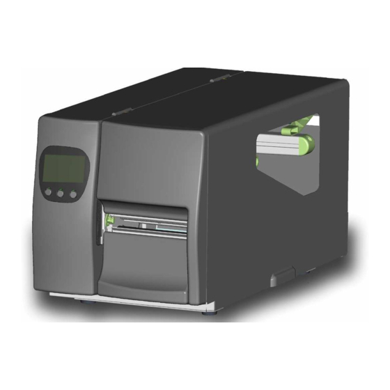
Page 17: Printer Parts
1-4. Printer Parts Appearance Control panel Bottom Front Cover Observing Window Top Cover Fan-Fold Label Insert CF Card Slot Serial Port * USB Port Power Switch Power Socket Fan-Fold Label Insert * The communication ports may vary depending on product types. - Page 18 Internal Ribbon Rewind Shaft Ribbon Supply Shaft Printer Mechanism Platen Tear off Bar Print Head Lever Sensor Knob Label Guide Label Tension Plate Label Roll Bar Label Supply Guide Label Alignment Guide Movable sensor EZ-2000+/6000+ User’s Manual Rev. D...
-
Page 19: Control Panel
Control Panel MEDIA LED RIBBON LED POWER LED LCD (Product type dependent) CANCEL Key PAUSE Key FEED Key MINUS (-) Key (In setting mode) MENU Key (In setting mode) PLUS (+) Key (In setting mode) EZ-2000+/6000+ User’s Manual Rev. D... -
Page 20: Printer Installation
2. Printer Installation This printer model has the following print modes: Thermal Transfer When printing, ribbon must be installed to transfer the print contents onto the (TT) media. Direct Thermal When printing, no ribbon is necessary; it only requires direct thermal media. - Page 21 Place the label roll onto the Label Roll Bar and align the label to printer’s inner wall. (To avoid the damage of media, please do not squeeze label roll too hard.) Pull the Label Alignment Guide back and make it fit the edge of label roll.
- Page 22 Align the label edge inward, and fix the label outside in Label Guide. Adjust the Label Guide with the label. 【 】 Note The Label should be put within Label Feed Guide as the figure shows. 10. Flip the Print Head Lever back to its original position.
-
Page 23: Ribbon Installation
2-2. Ribbon Installation Place the printer on a horizontal surface, and open the top cover. Follow the sequence and direction as the figure shows, pull the Print Head Lever out and flip it upward to the right. Place a new ribbon... - Page 24 Feed the ribbon from the Ribbon Supply Shaft under the print head. Wrap the ribbon around the Ribbon Rewind Shaft and stick it onto the empty ribbon roll. 【 】 Note DO NOT feed the ribbon under the Moveable Sensor. EZ-2000+/6000+ User’s Manual Rev.
-
Page 25: Pc Connection
Connect the cable to the USB/parallel port on both side of printer and PC. Power on the printer, the LCD display would show the printer model and F/W version. EZ-2000+/6000+ User’s Manual Rev. D... -
Page 26: Driver Installation
Insert the product CD, select ‘Specify a location’ and describe the path of the printer driver. Follow the instruction on the Window and complete the driver installation. EZ-2000+/6000+ User’s Manual Rev. D... -
Page 27: Accessory
】 Note Peel-off liner Max width: 118mm 【 】 Suggestion Liner thickness: 0.06mm~0.25mm Place the printer onto a smooth surface, open the top cover and face the printer sideways. 【 】 Note Before the installation, please power off the printer first. - Page 28 Take off the U Shape Clip from the Liner Rewind Shaft. Secure the Rewinder unit onto the printer. After the Rewinder is installed, plug the Rewinder Cable Connector onto the Rewinder Connector. Rewinder Installation completes. EZ-2000+/6000+ User’s Manual Rev. D...
-
Page 29: Rewind Bracket Installation For Ez-2000 Plus
3-2. Rewind Bracket Installation for EZ-2000 Plus Face the printer front, and unscrew the bottom cover screw. Remove the bottom front Cover. 【 】 Note Before the installation, please power off the printer first. Mount the label rewind bracket onto the printer mechanism and secure the screws into place. - Page 30 Label rewind bracket and Rewinder installation. 【 】 Note1 Before starting to rewind labels, please make sure the printer’s Label Rewind Bracket is installed properly as instructed. 【 】 Note2 When use stripper function, Please dismount the rewind bracket first.
-
Page 31: Stripper Installation For Ez-2000 Plus
3-3. Stripper Installation for EZ-2000 Plus Face the printer front, and unscrew clockwise the bottom front cover screw. Remove the bottom front cover. 【 】 Note Before the installation, please power off the printer first. After Rewinder installation complete, face the printer sideways. - Page 32 Note Make sure the liner rewind is in correct direction. 10. Screw the bottom front cover back onto the printer. 11. Press lower part of the stripper sensor to flip it open. 12. Flip the stripper sensor to the sensor detects position.
-
Page 33: Cutter Installation
【 】 Note Please power off the printer before installing the cutter module. Open the top cover and unscrew the two screws in the front to remove the tear off bar. EZ-2000+/6000+ User’s Manual Rev. D... - Page 34 Install the media into the printer. Close the Top Cover to complete the cutter installation. 【 】 Note1 Make sure the printer is set to activate cutter function on. 【 】 Note2 The label / paper used for cutting is suggested to be at least 30mm in height.
-
Page 35: Parallel/Ps2 Adapter Installation
Connector Cable Screw x 2pcs Make sure the power is off and the power cable is unplugged. Place the printer onto a smooth surface and open the top cover. Unscrew two screws as indicated in figure and remove the left top cover from the printer. - Page 36 Align the Parallel/PS2 module to the parallel port and secure the module onto the back plate. Connect one end of the 30 pin connector cable to the main board and the other end to the Parallel/PS2 module. The Parallel/PS2 module installation is complete.
-
Page 37: Control Panel
4. Control Panel 4-1. Control Panel Introduction Without LCD monitor With LCD monitor EZ-2000+/6000+ User’s Manual Rev. D Control keys FEED PAUSE CANCEL LED indicators Power Power on After turning on the power, the Ribbon and Media lights Ready(Power) will flash alternately until the completion of initialization. -
Page 38: Control Keys Introduction
Pressing the Pause key while printing, printer will pause the print job. When the Pause key is pressed one more time, the printer will continue with the rest of the print job. For example, if the print job contains 10 labels, press the Pause key to stop printing after 2 labels are printed. - Page 39 3 times. Press and hold & keys and turn on the printer until the buzzer beeps 2 times. The printer setting will go to default. Press and hold key and turn on the printer until the buzzer beeps once.
-
Page 40: Setting Mode
4-3. Setting mode In the Setting Mode, changes can be made according to requirement on the printing mode, options, media type, and parallel interface (printer can only go into setting when connected to PC by parallel cable, USB cable, or serial cable). - Page 41 With LCD monitor Press and hold key about 3 to 4 seconds until the buzzer beep 3 times and LCD shows Setting mode. The LCD monitor will show different options on the bottom. Below are general descriptions of setting items. Darkness Speed Stop Position...
- Page 42 Baud Rate: Default - 9600 bits 4800 bits 9600 bits 19200 bits 38400 bits 57600 bits 115200 bits Parity: Default - None Parity COM Port Set None Parity Odd Parity Even Parity Data Bits: Default - 8 bits 7 bits 8 bits Stop Bits: Default - 1 bit...
- Page 43 【 】 Note 2 Printer will store the previous settings after power off, thus if settings are to be changed again, please enter the Setting Mode to reset. EZ-2000+/6000+ User’s Manual Rev. D Default: ON ON: This function must install stripper or cutter.
- Page 44 The diagram of Setting Mode Items with the ”*" sign is default setting. EZ-2000+/6000+ User’s Manual Rev. D...
-
Page 45: Self-Test
The Self-Test function will help user to check whether the printer is operating normally. In Self-Test Mode, the printer will print out a test sample each time when the FEED key is pressed. Self-Test Mode, the printer will print out a test sample each time when the FEED key is pressed. -
Page 46: Dump Mode
Send commands to the printer, and check to see if the print result matches the commands sent. To cancel (get out of the Dump Mode), press the FEED key, this time printer will automatically print out “OUT OF DUMP MODE.” This indicates that printer is back in the standby mode. Or power off to exit the Dump Mode. -
Page 47: Error Messages
4-7. Error Messages If problems occur that prevent the printer printing normally, the printer will beep as warning, and error messages will be displayed. Quickly blinking LED Message Light Message Ribbon Media Display Print Head is opened Entering Cooling Process... - Page 48 Memory Full Rewinder Full Filename can not be found Filename repeated EZ-2000+/6000+ User’s Manual Rev. D Delete unnecessary 2 beeps Memory is data in the memory twice full or use CF Card. 2 beeps Rewinder is Remove the labels twice full on rewinder.
-
Page 49: Maintenance And Adjustment
5. Maintenance and Adjustment 5-1. Print Head Module Installation / Removal Instruction Open the top cover. 【 】 Note Power-off when removing print head module. Pull the Print Head Lever out and flip it upward to the right. 【 】 Note When remove print head module, please dismount... -
Page 50: Tph Print Line Adjustment
5-2. TPH Print Line Adjustment Please contact your local dealer for technical support Open the top cover. Pull the Print Head Lever out and flip it upward to the right. TPH print line adjustment: When the printing is stiff or printing with thick paper, the print line needs to be moved forward (paper feed direction) -
Page 51: Ribbon Tension Adjustment
Chapter5-6) If a narrower ribbon is used (especially when ribbon width is less than 2”), the printer might have problem to pull the labels. In this case, please decrease the tension by turning Ribbon Supply Shaft Knob counterclockwise. Moreover, the... -
Page 52: Thermal Print Head Cleaning
Print head cleaning instructions are as follows: Power-off the printer. Open the top cover. Take out the ribbon. Open the print head by lifting the Print Head Lever. -
Page 53: Print Head Balance And Pressure Adjustment
5-5. Print Head Balance and Pressure Adjustment Open the top cover. Pull the Print Head Lever out and flip it upward to the right. When printing with different label materials or using different ribbon types, unbalanced print quality may occur due to the media material differences. -
Page 54: Ribbon Shield Adjustment
5-6. Ribbon Shield Adjustment Due to the differences in the ribbon materials, if ribbon wrinkles occur during printing, please adjust the ribbon shield screw. Example: If ribbon wrinkles occur as (a), please turn the ribbon shield screw A clockwise, and if ribbon wrinkles occur as (b), please turn the ribbon shield screw B clockwise. -
Page 55: Adjust The Cutter
After the format is complete, a file folder named “Godex” would be created automatically. This folder is for storing all the data from the printer, please don’t do any change on it. The capacity of CF Card that is supported by the printer is from 128MB to 1GB. -
Page 56: Troubleshooting
(if cutter is installed) Check if label is placed upside down or if label is not suitable for the application Select the correct printer driver Select the correct label and print type Clean the label jam, and if label is stuck on Thermal Print Head, please remove it by using soft cloth with alcohol.
Need help?
Do you have a question about the EZ-2000 PLUS and is the answer not in the manual?
Questions and answers