Godex EZ-2000Plus User Manual
Hide thumbs
Also See for EZ-2000Plus:
- User manual (56 pages) ,
- Programmer's manual (44 pages) ,
- User manual (64 pages)
Table of Contents
Advertisement
Quick Links
Advertisement
Table of Contents

Subscribe to Our Youtube Channel
Related Manuals for Godex EZ-2000Plus


Summary of Contents for Godex EZ-2000Plus
- Page 1 User’s Manual EZ-2000Plus / EZ-6000Plus P/N. 920-011911-02 Rev. C, 06.2009...
- Page 2 FCC COMPLIANCE STATEMENT FOR AMERICAN USERS This equipment has been tested and found to comply with the limits for a CLASS A digital device, pursuant to Part 15 of the FCC Rules. These limits are designed to provide reasonable protection against harmful interference when the equipment is operated in a commercial environment.
-
Page 3: Safety Instructions
Safety Instructions Bitte die Sicherheitshinweise sorgfältig lesen und für später aufheben. Die Geräte nicht der Feuchtigkeit aussetzen. Bevor Sie die Geräte ans Stromnetz anschließen, vergewissern Sie Sich, dass die Spannung des Geräts mit der Netzspannung übereinstimmt. Nehmen Sie das Gerät bei Überspannungen (Gewitter) vom Netz. Das Gerät könnte sonst Schaden nehmen. - Page 4 Safety Instructions Please read the following instructions seriously. Keep the equipment away from humidity. Before you connect the equipment to the power outlet, please check the voltage of the power source. Disconnect the equipment from the voltage of the power source to prevent possible transient over voltage damage.
-
Page 5: Table Of Contents
2-4. Driver Installation ......................22 3. ACCESSORY....................24 3-1. Internal Rewinder for EZ-2000Plus................24 3-2. Rewind Bracket Installation for EZ-2000Plus (with rewinder)........26 3-3. Stripper Installation for EZ-2000Plus (with rewinder) ........... 27 3-4. Internal Rewinder for EZ-6000Plus................29 3-5. Stripper Installation for EZ-6000Plus (with rewinder) ........... 34 3-6. - Page 6 APPENDIX ....................... 68 1. EZ-2000Plus Certifications....................68 2. EZ-6000Plus Certifications....................73 EZ-2000+/6000+ User’s Manual...
-
Page 7: Barcode Printer
Barcode printer Power cable USB Cable Label Roll Sample Ribbon Empty Ribbon Roll Quick Start Guide CD (includes label editing software QLabel-IV / Manual) EZ-6000Plus EZ-2000Plus 1-2. General Specifications Model EZ-2100Plus EZ-2200Plus EZ-2300Plus Print Method Thermal Transfer / Direct Thermal Resolution... - Page 8 Label design software: QLabel-IV (for EZPL only) Software Driver & DLL: Windows 2000, XP and Vista Bitmap fonts: 6, 8, 10, 12, 14, 18, 24, 30, 16X26 and OCR A & B Bitmap fonts 90°, 180°, 270° rotatable, single characters 90°, 180°, 270° Resident Fonts rotatable Bitmap fonts 8 times expandable in horizontal and vertical directions...
- Page 9 Model EZ-6200Plus EZ-6300Plus Print Method Thermal Transfer / Direct Thermal 203 dpi (8 dot/mm) 300 dpi (12 dot/mm) Resolution Print Speed 6 IPS (150 mm/s) 4 IPS (100 mm/s) Print Width 6.61” (168 mm) Min. 0.39” (10 mm); Min. 0.39” (10 mm); Print Length Max.
- Page 10 Operation temperature: 41°F to 104°F (5°C to 40°C) Environment Storage temperature: -4°F to 122°F (-20°C to 50°C) Operation: 30-85%, non-condensing. Humidity Storage: 10-90%, non-condensing. Agency CE(EMC), FCC Class A, CB, cUL, CCC Approvals Length: 20.31” (516 mm) Dimension Height: 11.22” (285 mm) Width: 13.58”...
-
Page 11: Communication Interface
1-3. Communication Interface Parallel Interface Handshake : DSTB connects to the printer, BUSY connects to the host Interface cable : Parallel cable compatible to IBM PC Pin out : See below PIN NO. FUNCTION TRANSMITTER /Strobe host / printer Data 0-7 host /Acknowledge printer... - Page 12 USB Interface Connector Type : Type B PIN NO. FUNCTION VBUS PS2 Interface PIN NO. FUNCTION DATA CLOCK PS2 interface from PC to printer Printer Keyboard DATA DATA CLOCK 5 CLOCK Internal Interface UART1 wafer Ethernet module E_MD E_MD E_RST E_RST UART2 wafer Expansion module...
- Page 13 Applicator wafer Applicator module +24V +24V Printing (out) Printing Print error (out) Print error Printed (out) Printed Print (in) Print EZ-2000+/6000+ User’s Manual...
-
Page 14: Printer Parts
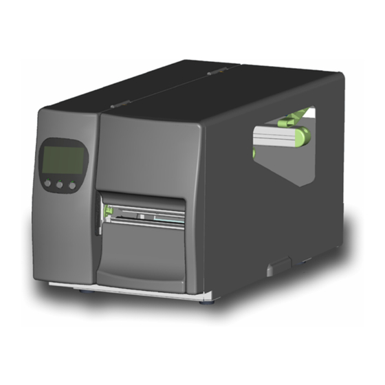
1-4. Printer Parts Appearance Control panel Bottom Front Cover Observing Window Top Cover Fan-Fold Label Insert CF Card Slot Serial Port Socket (Optional) Antenna Socket for WLAN Module (Optional) Ethernet Port RS-232 Port (DB-9) PS2 Port Socket (Optional) Applicator Interface Socket (Optional) USB Port Power Switch Power Socket... - Page 15 Internal Ribbon Rewind Shaft Ribbon Supply Shaft Printing Mechanism Platen Tear off Bar Print Head Lever Sensor Knob Label Guide Label Tension Plate Label Roll Bar Label Supply Guide Label Alignment Guide Movable sensor EZ-2000+/6000+ User’s Manual...
- Page 16 Control Panel MEDIA LED RIBBON LED POWER LED LCD (Product type dependent) CANCEL Key PAUSE Key FEED Key MINUS (-) Key (In setting mode) MENU Key (In setting mode) PLUS (+) Key (In setting mode) EZ-2000+/6000+ User’s Manual...
-
Page 17: Printer Installation
2. Printer Installation This printer model has the following print modes: Thermal Transfer When printing, ribbon must be installed to transfer the print contents onto the (TT) media. Direct Thermal When printing, no ribbon is necessary; it only requires direct thermal media. (DT) Please check the specific print mode, and then go into the Setting Mode after power on the printer 。... - Page 18 Place the label roll onto the Label Roll Bar and align the label to printer’s inner wall. (To avoid the damage of media, please do not squeeze label roll too hard.) Pull the Label Alignment Guide back and make it fit the edge of label roll.
- Page 19 Align the label edge inward, and fix the label outside in Label Guide. Adjust the Label Guide with the label. 【 】 Note The Label should be put within Label Feed Guide as the figure shows. 10. Flip the Print Head Lever back to its original position.
-
Page 20: Ribbon Installation
2-2. Ribbon Installation Place the printer on a horizontal surface, and open the top cover. Follow the sequence and direction as the figure shows, pull the Print Head Lever out and flip it upward to the right. Place a new ribbon roll onto the Ribbon Supply Shaft and place the... - Page 21 Feed the ribbon from the Ribbon Supply Shaft under the print head. Wrap the ribbon around the Ribbon Rewind Shaft and stick it onto the empty ribbon roll. 【 】 Note DO NOT feed the ribbon under the Moveable Sensor. EZ-2000+/6000+ User’s Manual...
-
Page 22: Pc Connection
2-3. PC Connection Please make sure the printer is powered off. Take the power cable, plug the cable switch to the power socket, and then connect the other end of the cable to the printer power socket. Connect the cable to the USB/parallel port on both side of printer and PC. Power on the printer, the LCD display would show the printer model and F/W version. -
Page 23: Driver Installation
2-4. Driver Installation Insert the product CD to your computer’s CD Drive and find the "Windows Drives" folder. Select the icon of driver file and click it to start the installation. Follow the instruction on screen to keep the installation going. Select the printer port that is used to connect the printer. - Page 24 Decide the printer name. Follow the instruction on screen to set "Printer Sharing" and "Print Test Page". A description page of printer settings will be displayed after all settings are completed. Check if all printer settings are correct and then press Finish to start copying driver files.
-
Page 25: Accessory
3. Accessory 3-1. Internal Rewinder for EZ-2000Plus Rewinder Paper Clip Screw x 4pcs Rewind bracket 【 】 Note Peel-off liner Max width: 118mm 【 】 Suggestion Liner thickness: 0.06mm ~ 0.25mm Place the printer onto a smooth surface, open the top cover and face the printer sideways. - Page 26 After the Rewinder is installed, plug the Rewinder Cable Connector onto the Rewinder Connector. Rewinder Installation completes. 【 】 Note The maximum length of rewound label is the total length of a label roll that with 8" OD and 3" core. EZ-2000+/6000+ User’s Manual...
-
Page 27: Rewind Bracket Installation For Ez-2000Plus (With Rewinder)
3-2. Rewind Bracket Installation for EZ-2000Plus (with rewinder) Face the printer front, and unscrew the bottom cover screw. Remove the bottom front Cover. 【 】 Note Before the installation, please power off the printer first. Mount the label rewind bracket onto the printer mechanism and secure the screws into place. -
Page 28: Stripper Installation For Ez-2000Plus (With Rewinder)
3-3. Stripper Installation for EZ-2000Plus (with rewinder) Face the printer front, and unscrew clockwise the bottom front cover screw. Remove the bottom front cover. 【 】 Note Before the installation, please power off the printer first. After Rewinder installation complete, face the printer sideways. - Page 29 Wrap the liner around the Liner Rewinder Shaft, and use the Paper Clip to secure the liner. Flip the print head lever downward and then push it back to the original position. 【 】 Note Make sure the liner rewind is in correct direction.
-
Page 30: Internal Rewinder For Ez-6000Plus
3-4. Internal Rewinder for EZ-6000Plus Motor Module Rewinder Module Rewinder Full Sensor Connector Plate Paper Clip Label Rewind Bracket Wire Binder Belt Screw x 10pcs Place the printer onto a smooth surface and open the Top Cover. Unscrew all screws that marked in square as indicated in figure. - Page 31 Unscrew the two screws of Standard Connection Plate from inside of printer and remove the Standard Connection Plate. Install the Rewinder Full Sensor Connector Plate with screws that removed from Standard Connection Plate. Plug the connector of Rewinder Full Sensor Connector Plate into the socket of main board as indicated in figure.
- Page 32 13. Rewinder Module installation is complete. 14. Put the Motor Module on rear part of printer and align it to 4 screw holes. 15. Tighten but don’t fully tighten the screws to save space for adjustment when installing the belt. 16.
- Page 33 17. Pull connection wires of Rewinder Module inside of printer through the hole. 18. Plug the 5pin connector into the socket on main board that marked with “CUTTER”. Plug the 4pin connector into the socket on main board that marked with “STRIP”. Plug the motor connector on top of Motor Module.
- Page 34 22. Unscrew the Bottom Cover Screw and remove the Bottom Front Cover. 23. Mount the Label Rewind Bracket onto the printer and secure it with screws. 24. Label Rewind Bracket installation is complete. 25. Install the ribbon and label on printer. 26.
-
Page 35: Stripper Installation For Ez-6000Plus (With Rewinder)
3-5. Stripper Installation for EZ-6000Plus (with rewinder) Stripper Module Cable Tie Mount x 2pcs Screws x 2pcs Unscrew the Bottom Cover Screw and remove the Bottom Front Cover. Unscrew the two screws to remove the Tear Off Bar. Hold the Stripper Module and secure it onto the printer. - Page 36 Loose the lock bar (as shown on the arrow 1) of the stripper. Follow the direction of arrow 2 to flip the stripper downward and open it. Peel off a few labels from the liner (about 400mm of liner), and then feed the liner through the stripper.
-
Page 37: Cutter Installation
3-6. Cutter Installation Cutter Cover (EZ-2000Plus) Cutter Cover (EZ-6000Plus) Cutter Cable Tie Mount x 2pcs Screws x 2pcs 【 】 Note1 Do not cut self-adhesive labels! The traces of adhesive will pollute the rotary knife and impair safe operation! 【... - Page 38 The label / paper that used for cutting is suggested to be at least 30mm in height. 【 】 Suggestion When printing with cutter module, it is suggested to set the stop position (^E) to 26 (for EZ-2000Plus)or 27 (for EZ-6000Plus). EZ-2000+/6000+ User’s Manual...
-
Page 39: Parallel/Ps2 Adapter Installation
3-7. Parallel/PS2 Adapter Installation Parallel Cable Parallel/PS2 Adapter Connector Cable Screw x 2pcs Make sure the power is off and the power cable is unplugged. Place the printer onto a smooth surface and open the top cover. Unscrew two screws as indicated in figure and remove the left top cover from the printer. - Page 40 Align the Parallel/PS2 module to the parallel port and secure the module onto the back plate. Connect one end of the 30 pin connector cable to the main board and the other end to the Parallel/PS2 module. 【 】 Note Please check the direction of pin and socket before plugging the connector cable.
-
Page 41: Applicator Interface Installation
3-8. Applicator Interface Installation Applicator Interface Screw x 2pcs 【 】 Note This applicator interface is only applicable to THARO company’s applicator product. For more detail about applicator products, please visit http://www.tharo.com/. Make sure the power is off and the power cable is unplugged. - Page 42 Plug the 10pin connector into the socket on mainborad that marked with “APP”. Align the Applicator Interface to the hole and hold the position. Tighten the screws to fix the Applicator Interface. Assemble the left top cover and close it to complete the installation. EZ-2000+/6000+ User’s Manual...
-
Page 43: Wlan Module Installation
3-9. WLAN Module Installation Ethernet Cable 1.8M Secure Screw*2 Bracket Screw*2 Module Bracket WLAN module Module Connection Wire WLAN Antenna Nut (for Antenna) Washer (for Antenna) Antenna Bracket Make sure the power is off and the power cable is unplugged. Place the printer onto a smooth surface and open the top cover. - Page 44 Connect the other end of Module Connection Wire to the main board. Mount the WLAN module and secure it onto the back plate. Thread Antenna Connection Wire through the hole on the Antenna Bracket. Mount the Antenna Connection Wire and Antenna Bracket on the back plate and secure it with screws.
- Page 45 10. Put the Washer first and then tighten the Nut on the Antenna Connection Wire. 11. Turn the Antenna according to the direction as arrow showed to mount it on the Antenna Connection Wire. The angle of Antenna can be adjusted if needed.
-
Page 46: Control Panel
4. Control Panel 4-1. Control Panel Introduction Without LCD monitor Control keys FEED PAUSE CANCEL LED indicators Power Power on After turning on the power, the Ribbon and Media lights Ready(Power) will flash alternately until the completion of initialization. Ribbon Ribbon status indication Media Media status indication... -
Page 47: Control Keys Introduction
4-2. Control Keys Introduction FEED Key After pressing the FEED key, printer will send the media (according to media type) to the specified stop position. When printing with continuous media, pressing the FEED key will feed media out to a certain length. When printing labels, pressing the FEED key will feed one label at a time;... - Page 48 With LCD monitor Item Beep LCD Message Description Press and hold key and turn + Power Self test 3 beeps Self test on the printer until the buzzer beeps 3 times. After entering Self test Mode, Dump 3 beeps Now in Dump + Power keep holding key until the...
-
Page 49: Setting Mode
4-3. Setting mode In the Setting Mode, changes can be made according to requirement on the printing mode, options, media type, and parallel interface (printer can only go into setting when connected to PC by parallel cable, USB cable, or serial cable). Power on the printer and make sure it is on “Ready to print”... - Page 50 With LCD monitor Press and hold key about 3 to 4 seconds until the buzzer beep 3 times and LCD shows Setting mode. The LCD monitor will show different options on the bottom. After entering to Setting mode, the first highlight on LCD monitor indicates the current item for setting.
- Page 51 Default: Gap paper Black Mark: for label or plain paper with black mark in the back Sensor Setup Gap: for labels with liner and gap, or hang tags. The default is set to be gap paper. Continuous: for continuous paper Baud Rate: Default - 9600 bits 4800 bits...
- Page 52 Windows 1255 Default: US French German Keyboard Setup Spanish Italian Finnish Dutch Belgian Default: Recall Label Recall Label: Recall label from memory card. Keyboard Setup: Setting the keyboard. Keyboard Mode Code page Setup: Setting the code page. Printing Option: Set the print quantity. Clock Setup: Set the clock and clock display.
- Page 53 The diagram of Setting Mode Items with the ” * " sign is default setting. EZ-2000+/6000+ User’s Manual...
-
Page 54: Self-Test
4-4. Self-Test The Self-Test function will help user to check whether the printer is operating normally. In Self-Test Mode, the printer will print out a test sample each time when the FEED key is pressed. To break off the Self-Test procedure, please power off the printer. Below are the Self-Test procedures: Power off the printer, press and hold the FEED key. -
Page 55: Dump Mode
4-5. Dump Mode When label setting and the print result don’t match, it’s recommended to go into the Dump Mode to check whether there’s a mistake in data transmission between the printer and the PC. For example, when printer receives 8 commands, yet without processing these commands, only printed out the contents of the commands, this will confirm whether the commands were received correctly. -
Page 56: Keyboard Mode
4-7. Keyboard Mode EZ-2000Plus / EZ-6000Plus series supports PS2 keyboard interface after Parallel/PS2 adapter module (optional) is installed. To connect the PS2 keyboard, please do as follows: Please be sure the printer power is on and is showing no error message. - Page 57 LCD will show the Serial Number Prompt. Key in the start value. (Example:00001) LCD will show the first Variable Prompt. Key in the variable data. (Example: Apple) 10. LCD will show the second Variable Prompt. 11. Key in the variable data. (Example: 199) 12.
- Page 58 14. The printer will print out 3 labels that include user-defined variables and serial number. EZ-2000+/6000+ User’s Manual...
-
Page 59: Error Messages
4-8. Error Messages If problems occur that prevent the printer printing normally, the printer will beep as warning, and error messages will be displayed. Quickly blinking Slowly blinking Light is on LED Message Light Beep Description Solution Message Ribbon Media Display Thermal Re-open the... - Page 60 Delete unnecessary Memory 2 beeps Memory is data in the memory Full twice full or use CF Card. Rewinder 2 beeps Rewinder is Remove the labels Full twice full on rewinder. Use “~X4” command to print Filename 2 beeps Can’t find out all the files, then can not be twice...
-
Page 61: Maintenance And Adjustment
5. Maintenance and Adjustment 5-1. Print Head Module Installation / Removal Instruction Open the top cover. 【 】 Note Power-off when removing print head module. Pull the Print Head Lever out and flip it upward to the right. 【 】 Note When remove print head module, please dismount... -
Page 62: Tph Print Line Adjustment
5-2. TPH Print Line Adjustment Please contact your local dealer for technical support Open the top cover. Pull the Print Head Lever out and flip it upward to the right. TPH print line adjustment: When the printing is stiff or printing with thick paper, the print line needs to be moved forward (paper feed direction) -
Page 63: Ribbon Tension Adjustment
5-3. Ribbon Tension Adjustment The ribbon shaft tension can be adjusted by turning the ribbon shaft knob clockwise or counterclockwise. There are 4 different levels of tension and marked with 1~4 on both knobs of Ribbon Rewind Shaft and Ribbon Supply Shaft. -
Page 64: Thermal Print Head Cleaning
5-4. Thermal Print Head Cleaning Unclear printouts (some parts of label cannot be printed) may be caused by dusty print head, ribbon stain, or label liner glue. Therefore when printing, it’s necessary to keep the top cover closed. Also, check and prevent paper/label from being stained or dusty to ensure print quality and to prolong the print head life. -
Page 65: Print Head Balance And Pressure Adjustment
Open the top cover. Pull the Print Head Lever out and flip it upward to the right. When printing with different label EZ-2000Plus materials or using different ribbon types, unbalanced print quality may occur due to the media material differences. Moreover, when one side of the printout is not printed clearly or ribbon wrinkle occurs, it’s... -
Page 66: Ribbon Shield Adjustment
5-6. Ribbon Shield Adjustment Due to the differences in the ribbon materials, if ribbon wrinkles occur during printing, please adjust the ribbon shield screw. Example: If ribbon wrinkles occur as (a), please turn the ribbon shield screw A clockwise, and if ribbon wrinkles occur as (b), please turn the ribbon shield screw B clockwise. -
Page 67: Adjust The Cutter
30mm in height. 5-8. CF Card Instruction All the EZ-2000Plus and EZ-6000Plus series models have built-in CF Card slot on the back of the printer. If the built-in memory is insufficient for storing label formats, graphics or fonts, users can use CF Card as external memory to provide more memory space. -
Page 68: Troubleshooting
Check if stripper sensor is covered with dust working correctly. Check if label is installed properly 【 】 Note Your dealer is knowledgeable about GODEX printers, printing software, and your unique system. Please contact your local dealer for technical support. EZ-2000+/6000+ User’s Manual... - Page 69 Appendix 1. EZ-2000Plus Certifications EZ-2000+/6000+ User’s Manual...
- Page 70 EZ-2000+/6000+ User’s Manual...
- Page 71 EZ-2000+/6000+ User’s Manual...
- Page 72 EZ-2000+/6000+ User’s Manual...
- Page 73 EZ-2000+/6000+ User’s Manual...
- Page 74 2. EZ-6000Plus Certifications EZ-2000+/6000+ User’s Manual...
- Page 75 EZ-2000+/6000+ User’s Manual...
- Page 76 EZ-2000+/6000+ User’s Manual...
- Page 77 EZ-2000+/6000+ User’s Manual...
- Page 78 EZ-2000+/6000+ User’s Manual...
Need help?
Do you have a question about the EZ-2000Plus and is the answer not in the manual?
Questions and answers