Table of Contents
Advertisement
Advertisement
Table of Contents

Related Manuals for Distech Controls ECLYPSE ECY-STAT


Summary of Contents for Distech Controls ECLYPSE ECY-STAT
- Page 1 ECLYPSE Connected Thermostat (ECY-STAT) User Guide...
- Page 2 ©, Distech Controls Inc., 2021. All rights reserved. While all efforts have been made to verify the accuracy of information in this manual, Distech Controls is not responsible for damages or claims arising from the use of this manual. Persons using this man-...
-
Page 3: Table Of Contents
Table of Contents ABLE OF ONTENTS CHAPTER 1 Introduction............................... 8 Overview .............................. 8 About the ECLYPSE Connected Thermostat ................ 8 About the IP Protocol Suite...................... 8 About BACnet®.......................... 8 About This User Guide.......................... 8 Purpose of the User Guide ...................... 8 Referenced Documentation ...................... - Page 4 Table of Contents About the 2.4 GHz ISM Band...................... 19 Distance Between the Wi-Fi Adapter and Sources of Interference.......... 19 About Wi-Fi Network Channel Numbers .................. 20 Radio Signal Range ........................ 20 Radio Signal Transmission Obstructions .................. 20 Where to Locate ECY-STAT thermostats ................... 21 Transmission Obstructions and Interference ................
- Page 5 Table of Contents CHAPTER 8 ECLYPSE Web Interface .......................... 42 Overview .............................. 42 Web Interface Main Menu...................... 43 Home Page .......................... 43 User Profile and Login Credentials ..................... 43 Network Settings ............................ 45 Ethernet ............................ 45 Wireless Configuration........................ 46 Network Diagnostics ........................ 48 BACnet Settings.............................
- Page 6 Table of Contents Passwords.............................. 98 Change the Default Platform Credentials ................... 98 Use Strong Passwords ....................... 98 Account Management and Permissions.................... 98 Use a Different Account for Each User .................. 98 Use Unique Service Type Accounts for Each Project.............. 99 Disable Known Accounts When Possible ...................
- Page 7 Table of Contents CHAPTER 14 ECY Controller Troubleshooting........................ 121 CHAPTER 15 Single Sign On (SSO) Troubleshooting...................... 122 CHAPTER 16 Wi-Fi Network Troubleshooting Guide ...................... 123 ECLYPSE Connected Thermostat (ECY-STAT)
-
Page 8: Introduction
This user guide also explains how to connect to the ECY-STAT’s configuration interfaces. About the IP Protocol Suite Distech Controls’ ECY-STAT controllers use a widely used IP protocol to communicate with each other and with other applications for control and supervision. What is commonly referred to as IP is actually a multi-layered protocol suite that reliably transmits data over the public Internet and privately fire- walled-off intranets. -
Page 9: Eclypse Introduction
Xpress Network Utility User Guide: This document is available on Distech Controls Documentation £ Portal EC- gfx Program User Guide: This document is available on Distech Controls Documentation Portal £ ECLYPSE Introduction The ECLYPSE series is a modular and scalable platform that is used to control a wide range of HVAC applications. -
Page 10: Acronyms And Abbreviations Used In This Document
Introduction Acronyms and Abbreviations Used in this Document Acronym Definition ASHRAE American Society of Heating, Refrigeration, and Air-Conditioning Engineers Access Point APDU Application Protocol Data Units Application Programming Interface ASCII American Standard Code for Information Interchange BACnet® Building Automation and Control Networking Protocol Building Automation System B-BC BACnet Building Controller... -
Page 11: Internet Protocol Suite Fundamentals
Internet Protocol Suite Fundamentals CHAPTER 2 Internet Protocol Suite Fundamentals This chapter describes the Internet protocol operating principles necessary to configure the IP param- eters of an IP controller. About the Internet Network The Internet is the world-wide interconnection of networks. At its root however, it is not one big net- work, but a group of networks that communicate between each other by using standard protocols and by using gateways between these networks called routers. - Page 12 Internet Protocol Suite Fundamentals Presentation layer: This layer implements the display of media such as images and graphics. £ Applications layer: This layer implements the process-to-process communications protocol that in- £ cludes among other services the BACnet/IP protocol, programming, debugging, WWW, and so on. All of the above IP suite protocol layers must be fully functional for any two devices or controllers to communicate with each other.
-
Page 13: Ipv4 Communication Fundamentals
IPv4 Communication Fundamentals CHAPTER 3 IPv4 Communication Fundamentals This chapter describes IPv4 Communication operating principles. DHCP Versus Manual Network Settings The following methods can be used to set the network settings: Manually set network settings allow precise control over the network’s configuration. This option £... -
Page 14: Networking Basics
See BBMD Settings. The table below contains the recommended network classes for the ECY-STAT. Refer to the Distech Controls IP Networking Guide for more information. Network Class CIDR Subnetwork... -
Page 15: Private Ipv4 Address Ranges
IPv4 Communication Fundamentals Private IPv4 Address Ranges Each IP address class has a private address range. Private IPv4 addresses cannot be routed over the Internet. ECY-STAT controllers will normally be assigned to a private IP address and are connected to the LAN ports of a router, thereby keeping them behind a firewall from the internet while allowing them to freely communicate to each other and to other trusted devices. -
Page 16: About Routers, Switches, And Hubs
IPv4 Communication Fundamentals Set the DNS IP address of the Domain Name System (DNS) servers in routers and in IP controllers that have manually-configured IP parameters. Between one and three DNS IP address is usually pro- vided by the Internet Service Provider (ISP). The second and third DNS addresses are for failover should the first DNS become unavailable. -
Page 17: Network Address Translation / Firewall
IPv4 Communication Fundamentals Network Address Translation / Firewall A router’s uplink port provides Network Address Translation (NAT) and firewall functions. NAT is a method to hide the private IP addresses of a range of devices (connected to LAN ports) be- hind a single IP address presented at the WAN uplink port. -
Page 18: Connecting Ip Devices To An Ip Network
100 Crimp RJ 45 Connectors CB-W5506E CB-W5506E Table 2: Distech Controls Recommended Cable Types to use for the Cat 5e Cable Subnetwork Bus 1. Outer cable diameter – This does not take into account the RJ-45 connector. ECLYPSE Connected Thermostat (ECY-STAT) -
Page 19: Connecting The Network Cable To The Ecy-Stat
Connecting IP Devices to an IP Network Connecting the Network Cable to the ECY-STAT To connect ECY-STAT controllers to an Ethernet network and then discover them, see chapter First Time Connection to an ECY-STAT. Wireless Network Connection To wirelessly connect to an ECY-STAT for the first time, see First Time Connection to an ECY-STAT. -
Page 20: About Wi-Fi Network Channel Numbers
Connecting IP Devices to an IP Network About Wi-Fi Network Channel Numbers Wi-Fi communications use a slice of radio spectrum or channel width for data transmission. In general terms, the amount of channel width required is proportional to the data transmission rate. Wi-Fi net- works operate in a number of different frequency ranges or bands such as the 2.4 GHz band. -
Page 21: Where To Locate Ecy-Stat Thermostats
Connecting IP Devices to an IP Network Wall Material Range Reduction vs. LoS Wood, drywall, glass (uncoated, without metal) 0 – 10% Brick, particle board 5 – 35% Metal, steel-reinforced concrete, mirrors. 10 – 90% Where to Locate ECY-STAT thermostats Where to Locate ECY-STAT thermostats When installing the ECY-STAT, it is important to ensure that distances and obstructions do not impede transmission. -
Page 22: Planning A Wireless Network
Connecting IP Devices to an IP Network Planning a Wireless Network A wireless network can be installed in many different types of floor spaces, large or small: office space, commercial space, residential space, etc. The following provides an example on how to start planning a wireless network such as a large office space. -
Page 23: Eclypse Connected Thermostat Connection Modes
Connecting IP Devices to an IP Network 3. Draw circles to locate the ideal positions for your ECY-STAT as shown below: Radio Shading Down Wi-Fi Hotspot Wi-Fi Hotspot Elevator Channel 6 Shaft Channel 1 Elevator Shaft Staircase Radio Shading well Radio Shading Down Wi-Fi Hotspot... -
Page 24: Wi-Fi Client Connection Mode
Connecting IP Devices to an IP Network Typical application examples are shown below. Wi-Fi Client Connection Mode Cut installation costs by leveraging existing wireless infrastructure and by eliminating the need for Eth- ernet cables. This architecture is characterized by the point-to-point connection between an access point and a client-controller. -
Page 25: Wi-Fi Hotspot
Connecting IP Devices to an IP Network A second ECY-STAT controller can be configured as a wireless client. This can be used as a solution to ‘jump’ architectural features that are not compatible with wires such as glass atriums. To configure the Wi-Fi client connection mode, see Setting up a Wi-Fi Access Point Wireless Network. -
Page 26: Wireless Network Commissioning Architectures
Connecting IP Devices to an IP Network Wireless Network Commissioning Architectures Client to Access Point Configuration A laptop is connected through Wi-Fi, as a Wi-Fi client, to any ECY-STAT controller that has its wire- less settings configured as an Access Point. The other ECY-STAT controllers are configured as Wi-Fi Clients and are wirelessly connected to the same Access Point. -
Page 27: Client To Hotspot Configuration
Connecting IP Devices to an IP Network Client to Hotspot Configuration Laptop 1 is connected with an Ethernet cable to a router set as a switch (Subnetwork 2). The routers that are part of the wired network are configured, on their wireless side as a Wi-Fi Access Point (Sub- network 1). -
Page 28: Preparing For A Wired Initial Connection
Preparing for a Wired Initial Connection CHAPTER 5 Preparing for a Wired Initial Connection General Information Default User Credentials Use the following credentials to access the ECLYPSE Web Interface: Username: admin Password: admin This password is only valid for a first-time connection and you will be prompted to change it after your first login. -
Page 29: Connection Procedures
Preparing for a Wired Initial Connection Connection Procedures Follow these simple steps to get started with the ECLYPSE Connected Thermostat: There are two networking methods to connect to an ECY-STAT for the first time: Wi-Fi. £ Wired (Ethernet connection to a router that will act as a DHCP server). £... - Page 30 Next Steps... Once you have connected the ECY-STAT(s) to a network, you may proceed with the configurations using Distech Controls’ Xpress Network Utility to perform batch operations such as batch discovery, IP or WiFi configurations. See First Time Connection to an ECY-STAT.
-
Page 31: First Time Connection To An Ecy-Stat
First Time Connection to an ECY-STAT CHAPTER 6 First Time Connection to an ECY-STAT This chapter describes how to get started with an ECY-STAT. This includes connecting to the factory- default IP address to gain access to the controller’s configuration interfaces. Connecting to the ECY-STAT When connecting to the ECY-STAT for the first time, the goal is to gain access to the controller so that you can configure it to work in its future network environment. -
Page 32: Ecy-Stat Identification
First Time Connection to an ECY-STAT ECY-STAT Identification ECY-STAT controllers are uniquely identified on the network by their MAC address. This identifier is printed on a label located on the inside front cover. This MAC address is used as part of the controller’s factory-default Wi-Fi access point name and its hostname. -
Page 33: Ethernet Network Connection
First Time Connection to an ECY-STAT Ethernet Network Connection When first connecting the ECY-STAT to the Ethernet network, you must connect it to a router that will act as a DHCP server to provide the controller with an IP address for the initial connection and config- uration. -
Page 34: Configuring The Ecy-Stat
First Time Connection to an ECY-STAT Configuring the ECY-STAT Any of the following methods can be used to connect to the controller’s interface in order to configure Using the XpressNetwork Utility £ Using the controller’s IP address in the Web browser £... -
Page 35: Connecting To The Ecy-Stat's Configuration Web Interface
First Time Connection to an ECY-STAT Connecting to the ECY-STAT's Configuration Web Interface The ECY-STAT configuration can be made through the configuration Web interface to set all the ECY- STAT’s configuration parameters including the ECY-STAT’s IP address according to your network planning. -
Page 36: Supported Radius Server Architectures
Supported RADIUS Server Architectures CHAPTER 7 Supported RADIUS Server Architectures A RADIUS server is used to centralize user credentials (controller login username / password) across all devices. This chapter describes the supported RADIUS server architectures and how to configure a RADIUS server in EC-Net or in an ECY-STAT. -
Page 37: Radius Server Architectures
Supported RADIUS Server Architectures RADIUS Server Architectures Local Credential Authentication Each device has its own credential database in the local credential authentication architecture. This approach is labor-intensive as multiple credential database instances must be maintained. EC-gfxProgram EC-Net ECLYPSE ECLYPSE Controller A Controller B Key: Credential Database... -
Page 38: Eclypse-Based Centralized Credential Authentication
Supported RADIUS Server Architectures ECLYPSE-Based Centralized Credential Authentication The credential database is centralized in an ECLYPSE controller that is configured as a RADIUS server, to authenticate login requests made directly to it, and by other subscribed ECLYPSE con- trollers. This architecture is ideal when you are not using EC-Net on your network. EC-Net cannot subscribe to a remote RADIUS server. -
Page 39: Ec-Net-Based Centralized Credential Authentication
Supported RADIUS Server Architectures EC-Net-Based Centralized Credential Authentication The credential database is centralized in an EC-Net station to authenticate login requests made by all other subscribed ECLYPSE controllers. EC-gfxProgram EC-Net ECLYPSE ECLYPSE Controller A Controller B RADIUS A Cache A Cache B EC-Net Figure 23: EC-Net-Based Centralized Credential Authentication... -
Page 40: Configuring The Ec-Net Station's Restservice
Supported RADIUS Server Architectures Configuring the EC-Net Station's RestService To configure the REST service in EC-Net, refer to the EC- gfx Program Getting Started User Guide: Getting Started on EC-Net for ECB & ECY Series Controllers. Any ECLYPSE controller being con- nected to by the RestService must be able to authenticate the User name and password configured in the RestService configuration. -
Page 41: Information Technology Department-Managed Centralized Credentials Authentication
Supported RADIUS Server Architectures Information Technology Department-Managed Centralized Credentials Authentication The credential database is centralized in a Microsoft Windows Domain Active Directory Server to au- thenticate login requests made by other subscribed ECLYPSE controllers and EC-Net stations. EC-gfxProgram Niagara ECLYPSE ECLYPSE Controller A Controller B... -
Page 42: Eclypse Web Interface
ECLYPSE Web Interface CHAPTER 8 ECLYPSE Web Interface This chapter describes the ECY-STAT’s Web interface. Overview The ECY-STAT has a web-based interface that allows you to view system status, configure the con- troller, update the controller’s firmware, and access applications associated to your projects. Figure 27: Example of an ECLYPSE Controller’s Web Interface Welcome Home Page (options may vary) ECLYPSE Connected Thermostat (ECY-STAT) -
Page 43: Web Interface Main Menu
ECLYPSE Web Interface Web Interface Main Menu The sidebar contains the configuration menus that allow you to view and set the controller’s configura- tion settings including its IP address, Wi-Fi settings, users, controller’s firmware, and much more. The menus may vary according to the associated device licenses and the user’s access level. These configuration parameters are password protected. - Page 44 ECLYPSE Web Interface To Change Your Password 1. To change your password, click the profile icon and select Change Password. 2. Enter your current password and click Next. 3. Enter the new password twice to confirm and click Next. Your password is changed. Click the show password icon to see the password you are entering.
-
Page 45: Network Settings
ECLYPSE Web Interface Network Settings The Network menu is used to configure the ECY-STAT’s network interface and setup the wired and wireless network configuration parameters. The available menus are: Ethernet £ Wireless £ Diagnostic £ Ethernet The Ethernet screen is used for any wired IP connections that are made through the controller’s Ether- net Switch connector. -
Page 46: Wireless Configuration
ECLYPSE Web Interface Option DHCP Client: Enabled DHCP Client: Disabled If the ECY-STAT is connected to a If you want to manually configure the ECY-STAT’s network network that has an active DHCP settings (to have a fixed IP address for example) or in the case server, enabling this option will where the network does not have a DHCP server, disable this automatically configure the Wired IP... - Page 47 ECLYPSE Web Interface The Wireless connection parameters can be set as follows. Item Description On / Off Enable/disable the controller’s wireless features. Select the Wi-Fi network operating mode: Hotspot, Access-Point, or Client. Hotspot: This creates a Wi-Fi hotspot with a router. See Setting up a Wi-Fi Hotspot Wireless Network for how to configure this mode.
-
Page 48: Network Diagnostics
ECLYPSE Web Interface Network Diagnostics The Diagnostic menu provides a number of tools to diagnose network connectivity issues between controllers. Wi-Fi Monitor: shows the current performance of a Wi-Fi connection with another controller. £ Ping Monitor: shows the round trip time it takes for a ping packet to go to an IP address and £... - Page 49 ECLYPSE Web Interface Figure 31: Network Diagnostics – Ping Monitor Item Description Ip Address Target Enter the corresponding controller’s IP address for its Wi-Fi interface in Ip Address Target. Start Starts graphing the monitored data. Clear Clears the graph. ECLYPSE Connected Thermostat (ECY-STAT)
-
Page 50: Bacnet Settings
ECLYPSE Web Interface BACnet Settings This is where the BACnet interface parameters are set. General This sets the controller’s BACnet network parameters. Figure 32: General BACnet Settings Item Description Controller Name Set a descriptive name by which this controller will be known to other BACnet objects. Each controller on a BACnet intra-network (the entire BACnet BAS network) must have a unique Device ID Device ID. -
Page 51: Network Ip Port
ECLYPSE Web Interface Network IP Port This sets the IP network configuration parameters (on-board port) as well as the BACnet Broadcast Management Device (BBMD) and Foreign Device for intranetwork connectivity. Figure 33: BACnet IP Configuration - Network IP Ports BBMD Settings BACnet/IP devices send broadcast discovery messages such as “Who-Is”... -
Page 52: User Management
ECLYPSE Web Interface Foreign Device Settings Some BACnet/IP devices also support a feature called Foreign Device Registration (FDR). FDR allows a BACnet/IP device to send broadcast messages to a device with BBMD enabled. The BBMD-enabled device will then forward these broadcast messages to all other BBMDs and onto all other FDR de- vices. - Page 53 ECLYPSE Web Interface Figure 35: Adding Users in Server Mode 1. Click the Add User icon to add a new user or select a user and click edit to edit an exist- ing user. The User Details window is displayed. Figure 36: Adding a User 2.
- Page 54 ECLYPSE Web Interface 3. Click Next. The Roles options are displayed. Figure 37: User Details - Roles 4. Select the access levels the user will be able to use. Set one or more options according to the user’s role: ECLYPSE Roles Description Allows user access to the ENVYSION studio and viewer.
- Page 55 ECLYPSE Web Interface 6. Enter the URL of the web page you want to define as the landing page. The URL is the one found after the controllers' IP address or hostname. This should be copied from your Web browser’s ad- dress bar when you have navigated to the target page.
-
Page 56: Password Policy
ECLYPSE Web Interface 4. Click Save. To edit an existing user, select the user from the list and click the edit icon and to remove, click the delete icon Password Policy The password policy sets the minimum requirements for a valid password to help prevent common password cracking techniques. -
Page 57: Radius Server/Client Settings
ECLYPSE Web Interface Radius Server/Client Settings You can use the network’s RADIUS Server for user authentication management. RADIUS Server Settings When Radius Server is selected in the Server Settings tab, this controller can be used as a RADIUS server by other controllers on the network. In this scenario, the other controllers must be configured to use the Client RADIUS Server mode with this controller’s IP address. -
Page 58: Radius Client Settings
ECLYPSE Web Interface RADIUS Client Settings When Radius Server is selected in the Client Settings tab the following configuration parameters shown in the table below are available. This centralizes access management on the RADIUS server thereby saving time by eliminating the need to add users to each controller individually. The client RA- DIUS server can be another ECLYPSE controller, Microsoft Windows Domain Active Directory Server, or a suitably-configured EC-Net/EC-BOS station. - Page 59 ECLYPSE Web Interface Should the connection to the RADIUS server be temporarily lost, ECLYPSE controllers have a fall back authentication mode: Users that have already authenticated themselves with the RADIUS server and then the connection to the RADIUS server is lost, these users will still be able to login to the con- troller as their successfully authenticated credentials are locally cached.
-
Page 60: Single Sign On (Sso) Settings
ECLYPSE Web Interface Single Sign On (SSO) Settings The Single Sign On (SSO) service allows a user to use one set of login credentials (e.g.username and password) to access multiple ECLYPSE devices that are on the same network. This provides a secure centralized login method to authenticate users. -
Page 61: Sso Server Settings
ECLYPSE Web Interface SSO Server Settings The Server Settings tab allows you to select the type of server mode for the Server controller. The available modes are Single Sign On or Radius Server. When Type is set to Single Sign On (SSO), the controller will be defined as the SSO Server dedicated to authentication purposes. -
Page 62: Sso Client Settings
ECLYPSE Web Interface SSO Client Settings whaThe Client Settings tab allows you to select the type of client mode for the Client controller(s). When Type is set to Single Sign On (SSO), the controller will use the SSO server for authentication. Figure 47: Client Settings - Type When Type is set to Local, credentials are added to and managed by this controller. -
Page 63: Setting Up The Sso Functionality
ECLYPSE Web Interface Item Description Type Server type. Server IP address of the SSO server. This is the IP address of the ECLYPSE controller that was configured as the server. Server IP Address Note: An SSO server must be configured with a static IP address. If the SSO server IP address changes, you will have to reconfigure all SSO clients with the new IP address. - Page 64 ECLYPSE Web Interface Figure 49: SSO Server Settings 5. In Type, select Single Sign On (SSO). 6. In Access Token, an access token is displayed by default. If required, you can generate a new access token or manually enter a custom access token. This exact access token will be needed to setup the Client server (see next procedure Setting Up the SSO Client).
- Page 65 ECLYPSE Web Interface 6. In Type, select Single Sign On. Additional fields are displayed. Figure 51: SSO Client Settings 7. In Server IP Address, enter the server IP address of the controller that is configured as the Server (e.g., 192.168.0.10). 8. In Server Https Port, verify that the port number matches the HTTPS port number of the SSO server in System >...
- Page 66 ECLYPSE Web Interface 13. When setting up a new SSO connection, a message is displayed to notify you that a new certificate has been detected. To validate the authenticity of the server, click Continue. Figure 52: SSO New Certificate Detected 14. A new page is displayed confirming that the server settings are being applied. After approximately 1 minute, you can refresh your browser manually using the F5 key or close and reopen your browser.
-
Page 67: Setting Up The Sso Functionality Through A Radius Server
ECLYPSE Web Interface Setting Up the SSO Functionality through a Radius Server The following procedure will explain how to setup an EC-Net station as the Radius server. In turn, this will allow users residing in EC-Net to access the ECY Series controllers and the associated ENVYS- ION graphics on an SSO Client, through a web browser. - Page 68 4. Make sure that Licensed is set to true. This is true when the RadiusService is licenced on this sta- tion and is available. For more information about support pack licensing, see Licensing the EC-Net Support Package for a Non-Distech Controls Brand Station in the EC-gfxProgram Getting Started Guide.
- Page 69 ECLYPSE Web Interface 5. In Type, select Radius Server. 6. In Server IP Address, enter the IP address of the EC-Net Radius Server. 7. Set the port numbers as needed. Port values 1812 and 1813 are standard RADIUS port numbers but other port number can be used.
-
Page 70: Certificate Authentication With Sso
ECLYPSE Web Interface Certificate Authentication with SSO To avoid getting certificate authentication messages: Also see Saving a Certificate. 1. Go to the System menu and select the Web Server tab. 2. Click Export Authority Public Key. A certificate is downloaded (.crt file) and can be found in the Downloads folder. -
Page 71: System Settings
ECLYPSE Web Interface System Settings This is where you configure the controller’s date and time, Web interface, port numbers, secure web interface, and the license. A secure web interface requires a SSL certificate. Device Information This shows detailed information about the controller such as the firmware version, MAC address for each network interface, extension modules versions, and Wi-Fi information. -
Page 72: Updating The Firmware
ECLYPSE Web Interface Updating the Firmware The controller’s firmware can be updated through the Firmware Update file upload interface for an ECY-STAT. 1. In System settings under the Information tab, click Update located next to the firmware version. The Firmware Update window is displayed: Figure 54: The Firmware Update File Upload Interface 2. -
Page 73: Extensions
ECLYPSE Web Interface Column Heading Description eventID Sequential event number. timestamp Time of occurrence of a particular event (date and time of day) in GMT. user User ID or username. ipAddress IP address of the client making the request. type Event type as described in the previous table. - Page 74 ECLYPSE Web Interface 2. Upload the firmware file using one of the following firmware upload methods: – Click Upload Files to find the firmware file on your PC. – In Windows Explorer, find the firmware file on your PC and drag and drop it in the dotted area. The file upload starts followed by the firmware upgrade.
-
Page 75: Location And Time
ECLYPSE Web Interface Location and Time The Location/Time tab is used to configure the system date and time as well as the weather and cur- rent location. Figure 58: System Settings – Location, Date, and Time Item Description Set Time Automatically Toggle On or Off to automatically set the time based on the NTP Server. -
Page 76: Web Server Access
ECLYPSE Web Interface Web Server Access Figure 59: System Settings – Web Server Access Item Description Give this controller a label or nickname to identify it on the network. The hostname can be used in place of an IP address to identify this controller on the network. Hostname A hostname may contain only the ASCII letters 'a' through 'z' (case-insensitive), the digits '0' through '9', and the hyphen ('-'). - Page 77 ECLYPSE Web Interface Item Description Displays the certificate status: Status -File not found: No certificate has been imported. -Present: A certificate has been imported. Import Custom Upload a custom certificate. You can also drag and drop a certificate file in the dotted area. Certificate Password The password for the imported certificate.
- Page 78 ECLYPSE Web Interface 7. Install the certificate in the Trusted Root Certification Authorities store. Click Install Certificate. Figure 61: Installing the Certificate on the PC 8. Select Place all certificates in the following store. Click Browse. Figure 62: Selecting the Store ECLYPSE Connected Thermostat (ECY-STAT)
- Page 79 ECLYPSE Web Interface 9. Select Trusted Root Certificate Authorities and click OK. Figure 63: Selecting the Trusted Root Certification Authorities Store 10. Click Next. Click Finish. 11. Accept the warning. Click Yes. Figure 64: Accept the Warning Removing a Certificate After you hold the controller’s reset button for 20 seconds, the controller’s HTTPS security certificates will be regenerated.
-
Page 80: Licenses
ECLYPSE Web Interface 2. In the Certificate Manager, navigate to Certificates - Current User\Trusted Root Certification Authorities\Certificates. When you open this folder, certificates are displayed along with related details in the right pane. 3. Certificates for ECLYPSE controllers are named in the following ways: –... -
Page 81: Backup And Restore
ECLYPSE Web Interface Backup and Restore The Backup and Restore tab allows you to fully backup and restore the ECY-STAT such as the set- tings, extensions firmware, ENVYSION project, etc. The backup file is created on the ECY-STAT and can then be downloaded to the PC using the download option. The Backup and Restore window, shown below, is used to create a backup as well as import and re- store a backup. - Page 82 ECLYPSE Web Interface Creating a Backup The backup functionality guides you through a series of well-defined steps to easily create the data backup. 1. In the Backup & Restore main screen, click Create Backup. The options to create a new backup are displayed.
- Page 83 ECLYPSE Web Interface The USB key option is not available at this time. 6. In the Confirmation section, an overview of the data you selected to backup is displayed. Click Finish to create the backup. Keep in mind that space may be limited on your ECY-STAT, therefore, plan to download the backup to a PC shortly after.
- Page 84 ECLYPSE Web Interface Importing a Backup from your PC or USB Key The Importing a Backup from your PC functionality guides you through a series of well-defined steps to easily import and restore a backup located or your PC. 1. In the Backup & Restore main screen, click Import a Backup From PC. The restore options are displayed.
- Page 85 ECLYPSE Web Interface 4. Select the ENVYSION projects you wish to restore and click Next. 5. In the Confirmation section, an overview of the data you selected to restore is displayed and by default the Remove backup file after restore option is selected. When selected, the backup file will be removed after the device reboots.
- Page 86 ECLYPSE Web Interface Restoring a Selected File In the Backup & Restore main screen, a Restore button is available next to each backup file. This al- lows you to restore a selected backup file already available in the controller’s internal memory. 1.
-
Page 87: Iot
ECLYPSE Web Interface 4. In the Confirmation section, review the selected features you selected and select Remove backup file after restore to remove the backup file from the device after reboot if you wish. Click Finish. The restore process may take a few minutes. You cannot restore a backup which was created in a more recent firmware version than the one you are restoring to. - Page 88 ECLYPSE Web Interface The connection string information can be found in the following locations: DeviceID: The host ID can be copied from the ECLYPSE Web interface home page (Host Id pa- £ rameter). See Overview. Hostname and SharedAccessKey: These two strings can be retrieved from the Device Details win- £...
- Page 89 ECLYPSE Web Interface ECLYPSE Connected Thermostat (ECY-STAT)
-
Page 90: Ble Room Devices
ECLYPSE Web Interface BLE Room Devices The BLE Room Devices tab enables web configuration of the ECY-STAT’s Bluetooth low energy ® technology enabled features. The Bluetooth features must first be correctly programmed into the con- troller using EC- gfx Program before they will appear in this tab. BLE Room Devices The BLE Room Devices main screen presents the details of the Bluetooth enabled room device cur- rently programmed in your ECLYPSE controller. - Page 91 ECLYPSE Web Interface Item Description Apply Click Apply to apply and save all changes. Table 5: BLE Room Device Configuration Space Owners A Space Owner can have certain advanced controls over the ECY-STAT based on roles assigned to that person upon being added as a user in the Current User Database. To access the advanced set- tings on the ECY-STAT, a space owner requires knowledge of the exact name and password from the Current User Database that was assigned to that specific user.
- Page 92 ECLYPSE Web Interface Groups and Actions Sunblind Groups, Lighting Groups, and Custom Actions must first be added and configured with EC- gfx Program. See the EC- gfx Program User Guide for more information. Once they have been added, configured, and synchronized with the controller, they will now be visible in the Web Configuration page.
-
Page 93: Configuring The Eclypse Wi-Fi Wireless Networks
Configuring the ECLYPSE Wi-Fi Wireless Networks CHAPTER 9 Configuring the ECLYPSE Wi-Fi Wireless Networks The ECY-STAT supports a number of wireless network connection modes. This chapter describes how to configure a controller’s wireless network. See also ECLYPSE Connected Thermostat Connection Modes. -
Page 94: Setting Up A Wi-Fi Access Point Wireless Network
Configuring the ECLYPSE Wi-Fi Wireless Networks 1. Under Wireless Configuration, set wireless to On. 2. Set the Mode to Hotspot. 3. Choose whether the SSID should be hidden or not. 4. Set the name for this access point by which wireless clients will identify it in Network Name. 5. - Page 95 Configuring the ECLYPSE Wi-Fi Wireless Networks Figure 71: Access Point Wireless Network Settings Configure the controller’s ECLYPSE Wi-Fi adapter mode as a Wi-Fi access point as follows. 1. Under Wireless Configuration, set wireless to On. 2. Set the Mode to Access-Point. 3.
-
Page 96: Setting Up A Wi-Fi Client Wireless Network
Configuring the ECLYPSE Wi-Fi Wireless Networks Setting up a Wi-Fi Client Wireless Network This connects the controller as a client of a Wi-Fi access point. See Wi-Fi Client Connection Mode more information. Figure 72: Client Wireless Network Settings Configure the controller as a Wi-Fi client as follows. 1. - Page 97 Configuring the ECLYPSE Wi-Fi Wireless Networks 5. Set the encryption mode to be used by this access point in Encryption: – OPEN: this option should be avoided as it does not provide any wireless security which al- lows any wireless client to access the LAN. –...
-
Page 98: Securing An Ecy-Stat
Securing an ECY-STAT CHAPTER 10 Securing an ECY-STAT This section describes how to secure an ECY-STAT from unauthorized access and use. Introduction This chapter describes how to implement best security practices for ECY-STAT controllers. Security is built up layer upon layer to make the system more resistant to attacks. This involves taking simple but effective steps to implement built-in security features. -
Page 99: Use Unique Service Type Accounts For Each Project
Securing an ECY-STAT Suspending an account shuts-off a single user’s access to the controller – it does not disrupt many users. Permissions can be tailored to the needs of each user. A shared account may have more permissions than all users should have. A shared account has a shared password which is more likely to be leaked. -
Page 100: Make Sure That Controllers Are Behind A Vpn
Securing an ECY-STAT Make Sure that Controllers are Behind a VPN For off-site connections, ensure that users access the controllers through a Virtual Private Network (VPN). This helps to prevent an attack through eavesdropping on the communications channel to steal user credentials. -
Page 101: Rebooting Or Resetting The Controller
Rebooting or Resetting the Controller CHAPTER 11 Rebooting or Resetting the Controller This chapter describes how to recover control over the controller by rebooting it or resetting it to the factory default settings. Rebooting the Controller See Mounting Instructions in the ECLYPSE Connected Thermostat (ECY-STAT) Installation Guide for the front cover removal procedure. - Page 102 Rebooting or Resetting the Controller To reset the controller to its factory default settings: 1. Separate the front cover from the back plate. 2. Place the reset switch in the ON position. 3. Replace the front cover on the back plate. 4.
-
Page 103: Envysion Preloaded Applications
CHAPTER 12 ENVYSION Preloaded Applications The Distech Controls Preloaded ENVYSION applications provides out-of-the-box configuration pro- gramming and graphics for the most common RTU, FCU, and Zoning applications. Choose the re- quired equipment from the Config Parameters to display the corresponding wiring diagram. -
Page 104: Ecy-Stat-F
ENVYSION Preloaded Applications ECY-STAT-F Figure 75: ECY-STAT-F Preloaded Application Fancoil Unit Parameter Option Description Only cooling valve is present. It can be either an ON/OFF valve (DO5) or a Cool modulating valve (DUO7). Cooling valve and electric heat is present. It can be either an ON/OFF valve CoolElectHeat (DO4) or a modulating valve (DUO7). -
Page 105: Ecy-Stat-Z
ENVYSION Preloaded Applications ECY-STAT-Z Figure 76: ECY-STAT-Z Preloaded Application Zone Control Dampers for Heating If a duct inlet temperature reading is available and it is determined to be suitable for heating, the sec- ond 50 percent of the heating load is maintained by the damper adjusting between minimum and max- imum heating position to maintain the space temperature heating setpoint. -
Page 106: Navigating The User Interface
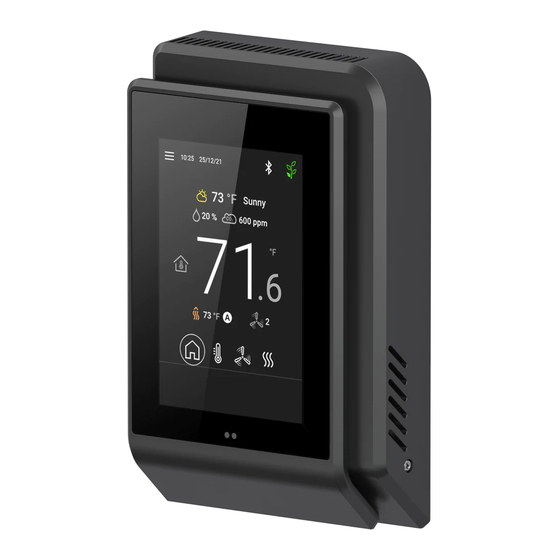
ECY-STAT. Simply tap the icons to access specific controls. When enabled in EC- gfx Program, your company’s logo (or the Distech Controls logo if left in the de- fault configuration) will alternate with the summary screen when Home is selected. -
Page 107: Main Menu
Tap the occupancy icon to manually toggle between unoccupied or occupied mode. Main Menu Tap the menu icon in the top left corner to access the main menu. The Distech Controls logo in the main menu screen is customizable and can be changed using EC- gfx Program. ECLYPSE Connected Thermostat (ECY-STAT) -
Page 108: My Personify App
Navigating the User Interface my PERSONIFY App Tap the my PERSONIFY App tab to reveal QR codes that can be scanned with your mobile device. The QR code is a shortcut download link for the ECY-STAT companion mobile application, my PER- SONIFY. -
Page 109: Settings
Navigating the User Interface Settings From the settings menu, a user can choose which units to display, the color theme, adjust the screen- saver timeout, and access the advanced settings. The current language is displayed here also. Item Description Indicates the display language used. The language can be changed using EC- gfx Program. Language Units Toggle the display units between Celsius and Fahrenheit. - Page 110 Navigating the User Interface Advanced Settings In the Advanced Settings, users can reset the Wi-Fi configuration. Item Description Bluetooth Bluetooth is always enabled. Bluetooth settings Bluetooth settings are not currently used. Wi-Fi configuration Tap to access an option that enables you to Reset the current Wi-Fi configuration. ECLYPSE Connected Thermostat (ECY-STAT)
- Page 111 Navigating the User Interface Resetting the Wi-Fi Configuration The Reset Wi-Fi Configuration option will re-activate the Hotspot on the ECY-STAT. It is used when an ECY-STAT in Wi-Fi client mode is unable to connect to its Hotspot, because of a wrong password, for instance.
-
Page 112: About
Navigating the User Interface About The About screen displays the current firmware and GUI versions, the controller’s Hostname, Ethernet IP and MAC addresses, as well as its Wi-Fi mode, IP and MAC addresses, and SSID. ECLYPSE Connected Thermostat (ECY-STAT) -
Page 113: Lighting Control
Navigating the User Interface Lighting Control The main lighting control can be configured here. The center graphic indicates the current light inten- sity level. Icon Description Tap and hold the slider icon to adjust the dimming level of the lights. Alternatively, you can tap a position on the slider to jump to that position. -
Page 114: Lighting Groups
Navigating the User Interface Lighting Groups Up to eight lighting groups can be used. The lighting groups must first be programmed using EC- gfx- Program and enabled or disabled using the ECLYPSE Web Interface. See the ECLYPSE User Guide and the EC- gfx Program User Guide for more information. Depending on the programmed configuration of the lighting groups, different options will be available for each group which are outlined below. -
Page 115: Temperature Control
Navigating the User Interface Temperature Control The main temperature settings can be adjusted here. Ambient temperature is displayed in the middle of the screen. Depending on the programming with EC- gfx Program, temperature will be displayed in either Absolute or Relative mode. Shown below is Absolute mode. Icon Description Tap and hold the slider icon to adjust the temperature setpoint. -
Page 116: Fan Control
Navigating the User Interface Fan Control The main fan settings can be controlled here. The center graphic displays the current fan speed set- ting. Depending on the programming with EC- gfx Program, Fan Control will be displayed in either Level or Analog mode. -
Page 117: Sunblind Control
Navigating the User Interface Sunblind Control The main controls for sunblinds can be found here. The center graphic displays the current sunblind vertical position. Icon Description Tap to select the desired sunblind rotational angle between 0 and 180 degrees. Availability of some rotational angles may be limited to the programmed settings. -
Page 118: Sunblind Groups
Navigating the User Interface Sunblind Groups Up to eight sunblind groups can be used. The sunblind groups must first be programmed using EC- gfx Program and enabled or disabled using the ECLYPSE Web Interface. See the ECLYPSE User Guide and the EC- gfx Program User Guide for more information. Depending on the programmed configuration of the sunblind groups, different options will be available for each group which are outlined below. -
Page 119: Hvac Mode
Navigating the User Interface HVAC Mode The main HVAC controls can be found here. The center graphic displays the current HVAC mode set- ting. Icon Description The Eco icon toggles Eco mode ON. To turn Eco mode OFF, toggle another HVAC mode ON. The HVAC mode parameters are configured using EC- gfx Program. -
Page 120: Custom Actions
Navigating the User Interface Custom Actions Custom actions must first be programmed using EC- gfx Program and enabled or disabled using the ECLYPSE Web Interface. See the ECLYPSE User Guide and the EC- gfx Program User Guide for more information. Depending on the programmed configuration of the custom actions, different options will be available for each action. - Page 121 ECY Controller Troubleshooting CHAPTER 14 ECY Controller Troubleshooting You can use this Troubleshooting Guide to help detect and correct issues with the ECLYPSE Series controllers. Symptom Possible Cause Solution Fuse has blown (for Disconnect the power. Check the fuse integrity. Reconnect the power. 24V controllers) Verify that consistent polarity is maintained between all controllers and the Power supply polarity...
- Page 122 Single Sign On (SSO) Troubleshooting CHAPTER 15 Single Sign On (SSO) Troubleshooting You can use this Troubleshooting Guide to help detect and correct issues with the SSO functionality. Even though the following table provides a work around to the issues, in general, we highly recom- mend that you always find the solution to any problem you may encounter.
- Page 123 Wi-Fi Network Troubleshooting Guide CHAPTER 16 Wi-Fi Network Troubleshooting Guide Any wireless system consists of two or more Wi-Fi transceivers and a radio propagation path (Radio Path). Problems encountered can be any of the following. Symptom Possible Cause Solution If the low power jammer is close to the transceiver antenna, move low power jammer (PC, telephone, etc.) at least 6.5 feet (2 m) away from transceiver antenna.
- Page 124 ECY-STAT_UG_11_EN...
Need help?
Do you have a question about the ECLYPSE ECY-STAT and is the answer not in the manual?
Questions and answers