
Related Manuals for Stahl ispac 9185


Summary of Contents for Stahl ispac 9185
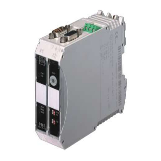
- Page 1 Typ/Type 9185 Feldbus-Trennübertrager Fieldbus-Isolating Repeater Betriebsanleitung Operating Instructions...
-
Page 2: Table Of Contents
Inhaltsverzeichnis Sicherheitshinweise ..................... 3 Normenkonformität ...................... 3 Funktion ........................4 Kennzeichnung und technische Daten ................. 4 Anordnung und Montage....................5 Maßzeichnung ....................... 5 Installation ......................5 Montage / Demontage auf Hutschiene ..............5 Inbetriebnahme Feldbus-Trennübertrager ..............6 Anschlüsse ......................6 Kompatibilität am Profibus DP Ex i................. -
Page 3: Sicherheitshinweise
Bei Einsatz in Zone 22 ist die Feldbus-Trennübertrager in ein Gehäuse einzubauen, das den Anforderungen der EN 61241-0 genügt (z.B. in ein Gehäuse Typ 8146 der Fa. R.STAHL Schaltgeräte GmbH). An die eigensicheren Signalstromkreise (9185/11) dürfen hier auch eigensichere Geräte der Zone 21 angeschlossen werden. -
Page 4: Funktion
Die Variante 9185/1*-46-10 dient zur Trennung der nichteigensicheren RS 232 und Profibus-DP Schnittstellen zur eigensicheren RS 422 Schnittstelle. Die Feldbus- Trennübertrager 9185/1x-46-10 wird zur Verbindung eines Profibusnetzwerkes mit Bediengeräten der Exicom-Reihe eingesetzt. 4 Kennzeichnung und technische Daten Hersteller R. STAHL Typbezeichnung 9185/ 11-**-10 9185/12-**-10 CE-Kennzeichnung 0158... -
Page 5: Anordnung Und Montage
Bereiche zu installieren. Bei Betrieb in Zone 2 ist der Feldbus-Trennübertrager in ein Gehäuse einzubauen, das den Anforderungen der EN 60079-15 genügt (z.B. in ein Gehäuse Typ 8146 der Fa. R.STAHL Schaltgeräte GmbH). Bei Betrieb in Zone 22 ist der Feldbus-Trennübertrager in ein Gehäuse einzubauen, das den Anforderungen der EN 61241-0 genügt (z.B. -
Page 6: Inbetriebnahme Feldbus-Trennübertrager
X1 Service und Programmierschnittstelle 6.2 Kompatibilität am Profibus DP Ex i Komponenten mit der bisherigen PROFIBUS DP Ex i Busphysik nach R. STAHL Spezifikation und Komponenten gemäß ´PROFIBUS RS485 IS´ PNO Spezifikation in einem Bussegment sind nicht mischbar, da sich funktionale Kenndaten unterscheiden. -
Page 7: Projektierung Ex I
Bestellnummer: 162699 Achtung! Nicht Ex PROFIBUS Stecker dürfen im Ex i –Segment nicht verwendet werden Ex PROFIBUS Stecker dürfen in nicht-Ex Segmenten nicht verwendet werden. Busanschluss an Geräte mit PROFIBUS Steckverbindern von R. STAHL Busphysik gemäß Gerät RS 485 IS PNO RS 485 Ex i Feldbus Trennübertrager... -
Page 8: Anschlussübersicht Und Belegung Der Stecker
Betriebsanleitung Busabschluss RS 485 IS PROFIBUS DP Exi gem. R. STAHL Spezifikation Abschluss Beide Busenden eines Segmentes aktiv Ex i Segment mit aktivem Abschluss- mit 200 Ohm abgeschlossen widerstand 120 Ohm abgeschlossen. Stecker für Profibus RS 485 IS gemäß PNO- Bestell-Nr. -
Page 9: Funktionsübersicht
SCAN Sender RS 422 Sender RS 422 Sendepegel Feldseite (X3) (bei RS2 = OFF) (bei RS2 = ON) abgeschaltet *) Direction Dauernd ein tastend R. STAHL PNO *) OF F OF F SCAN SCAN SCAN SCAN SCAN SCAN 6.7 Einstellungen 9185/11-45-10 Die Änderung der Schalter-Einstellungen ist im Betrieb auch in der Zone 2 und bei... -
Page 10: Einstellungen 9185/12-45-10
deutsch Betriebsanleitung 6.8 Einstellungen 9185/12-45-10 Die Änderung der Schalter-Einstellungen ist im Betrieb auch in der Zone 2 zulässig. Schnittstelle Systemseite (X2) RS 485 *) RS 422 *) = Standardeinstellung SCAN SCAN Sender RS 422 Sender RS 422 Schnittstelle Feldseite (X3) (bei RS2 = OFF) (bei RS2 = ON) abgeschaltet *) - Page 11 Betriebsanleitung deutsch Jumpereinstellung J1 bis J6 (9185/11-46-10) Mit den Lötjumpern J1 bis J6 werden die Parameter der seriellen Kommunikation zur Feldseite sowie weitere mögliche Funktionen eingestellt. Jumper J1 und J2 definieren die Baudrate für die Feldseite. Alle anderen Parameter für die Feldseite sind nicht veränderbar.
-
Page 12: Betrieb- Und Betriebszustände
deutsch Betriebsanleitung 7 Betrieb- und Betriebszustände Bevor Sie das Gerät in Betrieb nehmen, stellen Sie sicher, dass das Gerät vorschriftsmäßig im korrekten Steckplatz installiert wurde das Gerät nicht beschädigt ist die Kabel ordnungsgemäß angeschlossen sind Feldbus-Trennübertrager Übertragungsverhalten Alle drei Schnittstellen des Feldbus-Trennübertragers (X1 ... - Page 13 Betriebsanleitung deutsch LED Anzeigen Feldbus-Trennübertrager 9185/1*-46-10 Normalbetrieb Kürzel Farbe Bedeutung (Frontplatte) grün blinkt leuchtet Busfehler Bus in Ordnung blinkt Senden RS 422/485 Schnittstelle der grün Feldseite blinkt Empfang RS 422/485 Schnittstelle der grün Feldseite grün leuchtet Data Exchange SPC3 tauscht Daten aus Projektierung Bedienterminal Kürzel Farbe...
-
Page 14: Reparatur Und Instandhaltung
Kaufdaten, Fehlerbeschreibung, Einsatzzweck (insbesondere Eingangs-/Ausgangsbeschaltung) 9 Zubehör und Ersatzteile Verwenden Sie nur Original-Zubehör sowie Original-Ersatzteile der Fa. R.STAHL Schaltgeräte GmbH Bestellnummer Beschreibung 162693 Sub-D Ex i Profibus Stecker; Anschluss 9185/11 oder CPM 9440/*2 an „RS 485 IS PNO“... -
Page 15: Safety Instructions
EN 61241-0 (e.g. in an enclosure type 8146 from the R. STAHL Schaltgeräte GmbH company). In this case (9185/11), intrinsically safe devices of Zone 21 may also be connected to the intrinsically safe signal circuits. -
Page 16: Function
All 9185/11 and 9185/12 models serve to convert the various interfaces. The type 9185/1*-46-10 is additional in use for separation of the non-intrinsically safe RS 232 and Profibus-DP interfaces to the intrinsically safe RS 422 interface. 4 Marking and technical data Manufacturer R. STAHL Type 9185/ 11-**-10 9185/12-**-10 CE marking... -
Page 17: Arrangement And Fitting
In the case of operation in Zone 22, the field bus isolating repeater must be fitted in an enclosure which complies with the requirements of EN 61241-0 (e.g. in an enclosure type 8146 from the R. STAHL Schaltgeräte GmbH company). -
Page 18: Commissioning Fieldbus-Isolating Repeater
english Operating Instructions Put the device on the DIN rail. Take care that the cut out of the enclosure fits onto the edge of the DIN rail. Swivel the device until it is snapped on the DIN rail. Dismounting ... -
Page 19: Compatibility On Profibus Dp I.s
6.2 Compatibility on Profibus DP I.S. Components with the previous PROFIBUS DP I.S. bus topology to R. STAHL specification and components in accordance with ´PROFIBUS RS485 IS´ PNO specification cannot be mixed in a bus segment as the functional characteristics differ. -
Page 20: Planning And Engineering I.s
Bus termination in accordance with ´R. STAHL ´PROFIBUS RS485 IS´ specification specification´. See Manual ´Planning, Engineering, Installation and Commissioning of e.g. the RS 485 field bus system of R. STAHL for the with Sub-D Physics PROFIBUS plug safe area and hazardous area´ e.g. -
Page 21: Connection And Allocation Overview Of All Plugs
Operating Instructions english Bus termination RS 485 IS PROFIBUS DP Exi in accordance with R. STAHL specification Termination Both bus ends of the segment terminated I.S. segment with terminated with active actively with 200 Ohm terminating resistor 120 Ohm. Plug... -
Page 22: Functions
Transmitter RS 422 Transmitter RS 422 Transmit level, field-circuit (on RS2 = OFF) (on RS2 = ON) Ex i deactivated *) Direction Permanently Pulsed R. STAHL PNO *) OF F OF F SCAN SCAN SCAN SCAN SCAN SCAN 6.7 Settings 9185/11-45-10 The switch settings may be changed in operation in Zone 2 as well and in the case of connected, intrinsically safe input signals. -
Page 23: Settings 9185/12-45-10
Operating Instructions english 6.8 Settings 9185/12-45-10 The switch settings may be changed in operation even in Zone 2. Interface, system-circuit RS 485 *) RS -422 *) = Default setting SCAN SCAN Transmitter RS 422 Transmitter RS 422 Interface, field-circuit (on RS2 = OFF) (on RS2 = ON) Deactivated *) Direction... - Page 24 english Operating Instructions Jumpersettings J1 to J6 (9185/11-46-10) You can set the parameters of the serial communication to the field side as aditional functions via the jumpers J1 to J6. Jumper J1 and J2 defines the baudrate of the field side. All other parameters of the field side are not changeable.
-
Page 25: Operation And Operational States
Operating Instructions english 7 Operation and operational states Before commissioning the device, please ensure that: the device has been installed in the correct slot and in accordance with the standards the device is not damaged the cables are properly connected 7.1 Fieldbus-Isolating Repeater Transfer characteristics All three interfaces of the field bus isolating repeater (X1 ... - Page 26 english Operating Instructions LED indicators Fieldbus-Isolating Repeater (9185/1*-46-10) In Operation Abbreviation Color Function (front plate) green blinking illuminate Bus error Bus OK green blinking Send RS 422/485 interface field side green blinking Receive RS 422/485 interface field side green illuminate Data Exchange SPC3 exchanges data Download into operator interface Abbreviation Color...
-
Page 27: Maintenance And Repair
Operating Instructions english 8 Maintenance and repair It is recommended that all repairs to our devices be carried out by R. STAHL. In exceptional cases, repair may be performed by approved third-parties. The devices are maintenance-free. Troubleshooting chart Fieldbus-Isolating Repeater:... -
Page 28: Eg-Konformitätserklärung / Ec-Declaration Of Conformity
EG-Konformitätserklärung / EC-Declaration of Conformity... - Page 29 R. STAHL Schaltgeräte GmbH Am Bahnhof 30 74638 Waldenburg (Württ.) – Germany www.stahl.de ID-Nr. 227865 / 9185612310 2015-02-10•BA00•III•de•01...
Need help?
Do you have a question about the ispac 9185 and is the answer not in the manual?
Questions and answers