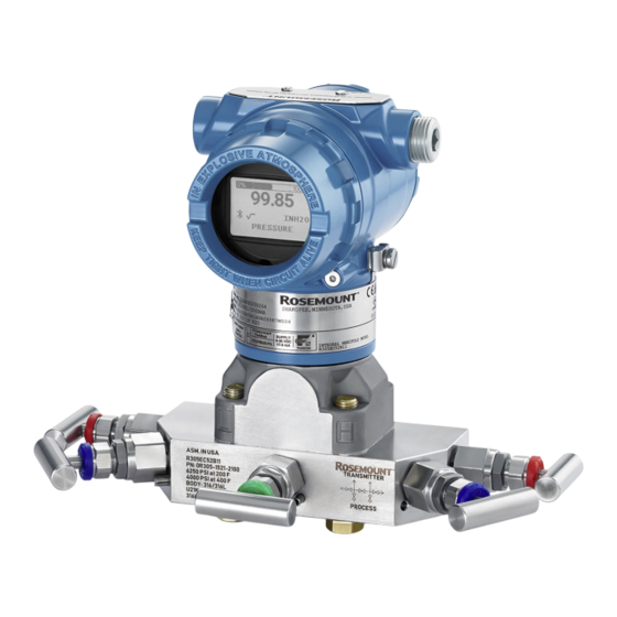
Emerson Rosemount 3051 Series Quick Start Manual
Pressure transmitter and flow meter with 4-20 ma hart and 1-5 vdc low power protocol
Hide thumbs
Also See for Rosemount 3051 Series:
- Quick start manual (52 pages) ,
- Quick start manual (34 pages) ,
- Quick start manual (52 pages)

Related Manuals for Emerson Rosemount 3051 Series


Summary of Contents for Emerson Rosemount 3051 Series
- Page 1 Quick Start Guide 00825-0100-4001, Rev MD November 2024 Rosemount 3051 Pressure ™ Transmitter and 3051CF Series Flow Meter with 4-20 mA HART and 1-5 Vdc Low ® Power Protocol...
-
Page 2: Table Of Contents
Quick Start Guide Contents About this guide........................... 3 Mounting the transmitter......................6 Rotate housing........................... 14 Set the switches......................... 15 Connect the wiring and power up................... 17 Verifying configuration......................22 Trimming the transmitter......................26 Safety Instrumented Systems (SIS)..................28 Product certifications........................ 32 www.Emerson.com... -
Page 3: About This Guide
• explosion-proof • flameproof • intrinsically safe installations This guide and the referenced manual are also available on Emerson.com/global. 1.1 Safety messages Before installing the transmitter, confirm the correct device driver is loaded on the host systems. WARNING Explosions Explosions could result in death or serious injury. - Page 4 This is true for all systems used within the facility. WARNING Refer to the Product certifications section of this Quick Start Guide documentation when using the RFID tag (option code Y3) for required installation conditions. www.Emerson.com...
- Page 5 M20 × 1.5 thread form. On devices with multiple conduit entries, all entries will have the same thread form. When installing in a hazardous location, use only appropriately listed or Ex-certified plugs, glands, or adapters in cable/conduit entries. www.Emerson.com...
-
Page 6: Mounting The Transmitter
Mount the transmitter in a liquid flow application A. Flow Procedure 1. Place taps to the side of the line. 2. Mount the transmitter beside or below the taps. 3. Mount the transmitter so that the drain/vent valves are oriented upward. www.Emerson.com... - Page 7 Mount the transmitter in a gas flow application NOTICE A bracket is required to support the transmitter and the ¼-inch tubing going into the transmitter. Procedure 1. Place taps in the top or side of the line. 2. Mount the transmitter beside or above the taps. www.Emerson.com...
- Page 8 November 2024 Quick Start Guide 2.3 Steam flow applications Figure 2-1: Steam Flow Application A. Flow Procedure 1. Place taps to the side of the line. 2. Mount beside or below the taps. 3. Fill impulse lines with water. www.Emerson.com...
- Page 9 Quick Start Guide November 2024 2.4 Panel and pipe mount Figure 2-2: Panel and Pipe Mounting Panel mount Pipe mount Coplanar flange ™ Traditional flange Rosemount 3051T Rosemount 3051H 5/16 x 1½ panel bolts are customer-supplied. www.Emerson.com...
-
Page 10: Bolting Considerations
Use only bolts supplied with the transmitter or sold by Emerson as spare parts. Figure 2-3 illustrates common transmitter assemblies with the bolt length required for proper transmitter assembly. -
Page 11: O-Rings With Flange Adapters
Failure to install proper flange adapter O-rings may cause process leaks, which can result in death or serious injury. The two flange adapters are distinguished by unique O-ring grooves. Only use the O-ring that is designed for its specific flange adapter, as shown in Figure 2-4. www.Emerson.com... - Page 12 The vent path is 360° around the transmitter between the housing and sensor. (See Figure 2-5.) To allow fluids to drain away, keep the vent path free of any obstruction, including but not limited to: • paint • dust • lubrication www.Emerson.com...
- Page 13 Quick Start Guide November 2024 Figure 2-5: In-line Gauge Low Side Pressure Port A. Pressure port location www.Emerson.com...
-
Page 14: Rotate Housing
7 in-lb when desired location is reached. NOTICE Over-rotating will damage the transmitter. Figure 3-1: Housing Rotation A. Housing rotation set screw (5/64 in.) Rosemount 3051C original position aligns with side; Rosemount 3051T original position is the opposite side of the bracket holes. www.Emerson.com... -
Page 15: Set The Switches
ON and OFF positions. 4. Reattach the transmitter cover. WARNING The cover must be fully engaged to comply with explosion- proof requirements. Figure 4-1: Transmitter Electronics Board Without display With LCD display A. Alarm switch B. Security switch www.Emerson.com... - Page 16 November 2024 Quick Start Guide Note Units with the graphical LCD display have jumpers in the same location as units without an LCD display. www.Emerson.com...
-
Page 17: Connect The Wiring And Power Up
Quick Service buttons ≥ 10.5 Vdc None Local operator interface ≥ 10.5 Vdc None (LOI) Resistance and power requirements vary based on the interface type used to communicate with the device. See Table 5-1 for specific loop power and resistance needs. www.Emerson.com... - Page 18 When using a direct wiring method, wrap wire clockwise to ensure it is in place when tightening the terminal block screw. NOTICE Emerson does not recommend using a pin or a ferrule wire, as the connection may be more susceptible to loosening over time or under vibration.
- Page 19 Use these terminations when transient protect terminal blocks are installed or to fulfill local regulations. See Step 2 for more information on how the cable shield should be grounded. Procedure 1. Remove the field terminals housing cover. www.Emerson.com...
- Page 20 D. Shield connected to power supply ground E. Insulate shield 3. Replace the housing cover. NOTICE Emerson recommends tightening the cover until there is no gap between the cover and the housing. 4. Plug and seal unused conduit connections. www.Emerson.com...
- Page 21 The total resistance load is the sum of the resistance of the signal leads and the load resistance of the controller, indicator, intrinsically safe (IS) barriers, and related pieces. If you use IS barriers, then include the resistance and voltage drop. www.Emerson.com...
-
Page 22: Verifying Configuration
Revision 6 fast key sequence. Figure 6-2: Device Dashboard - Device Revision 3 and DD Revision Note A check (✓) indicates the basic configuration parameters. At minimum, these parameters should be verified as part of the configuration and startup procedure. www.Emerson.com... - Page 23 Range Values 1, 3, 3 Rerange 1, 2, 3, 1 Scaled D/A Trim (4–20 mA Output) 1, 2, 3, 2, 2 Self Test (Transmitter) 1, 2, 1, 1 Sensor Info 1, 4, 4, 2 Sensor Temperature 1, 1, 4 www.Emerson.com...
- Page 24 Rerange with Keypad 2, 2, 2, 1 Loop Test 3, 5, 1 Lower Sensor Trim 3, 4, 1,2 Message 2, 2, 6, 1, 6 ✓Range Values 2, 2, 2 Scaled D/A Trim (4–20 mA Output) 3, 4, 2, 2 www.Emerson.com...
- Page 25 2, 2, 1, 6 2, 2, 6, 1,1 ✓Tag ✓Transfer Function 2, 2, 1, 3 Transmitter Security (Write Protect) 2, 2, 5, 1 2, 2, 1, 1 ✓Units Upper Sensor Trim 3, 4, 1, 1 Zero Trim 3, 4, 1, 3 www.Emerson.com...
-
Page 26: Trimming The Transmitter
Quick Start Guide 7 Trimming the transmitter Note Emerson ships transmitters fully calibrated per request or by the factory default of full scale (span = upper range limit). 7.1 Zero trim A zero trim is a single-point adjustment used for compensating mounting position effects. - Page 27 Quick Start Guide November 2024 2. Set the 4 mA point by pressing the Zero button for two seconds. Verify the output is 4 mA The optional LCD display will show ZERO PASS Figure 7-1: Zero Adjustment or Quick Service Buttons www.Emerson.com...
-
Page 28: Safety Instrumented Systems (Sis)
Figure 8-1 identifies the two alarm levels available and their operation values. Position the alarm switch to the required HI or LO alarm position. Figure 8-1: Rosemount Alarm Level A. Low saturation B. Normal operation C. High saturation www.Emerson.com... -
Page 29: Operation And Maintenance
8.3.1 Proof test and inspection The following proof tests are recommended. Proof test results and corrective actions taken must be documented Emerson.com/Rosemount/Report-A-Failure in the event that an error is found in the safety functionality. Use the fast key sequences in... - Page 30 Postrequisites Report all failures detected by the transmitter diagnostics or by the proof-test. You can submit feedback electronically at Emerson.com/ Rosemount/Report-A-Failure The Rosemount 3051 is repairable by major component replacement. Follow the instructions in the Rosemount 3051 Pressure Transmitter Reference Manual for additional information.
- Page 31 Quick Start Guide November 2024 Failure rate data Failure Modes, Effects, and Diagnostic Analysis (FMEDA) report includes failure rates and common cause Beta factor estimates. This report is available at Emerson.com/global. Safety failure values 0.065 percent Safety accuracy 100 msec Safety response...
-
Page 32: Product Certifications
This device must be installed to ensure a minimum antenna separation distance of 7.9 in. (20 cm) from all persons. Changes or modification to the equipment not expressly approved by Emerson could void the user's authority to operate the equipment. -
Page 33: Ordinary Location Certification
XP: CL I, DIV 1, GP B, C, D T5; Markings Seal not required DIP: CL II, DIV 1, GP E, F, G; CL III T5; (-50 °C ≤ T ≤ +[85 °C) Type 4X, IP 68 Optional: single seal www.Emerson.com... - Page 34 (option code T1) will not pass the 500 Vrms dielectric strength test, and this must be taken into account during installation. 1053834 Certificate Ranges 1-6 FM 3600: 2022, FM 3610: 2018, FM 3611: 2021, Standards ANSI/UL 61010-1-2019 Third Edition, ANSI/UL 60079-0: www.Emerson.com...
- Page 35 2005, ANSI/NEMA 250: 2008 ® IS: CL I, DIV 1, GP A, B, C, D T4; Markings CL II, DIV 1, GP E, F, G; CL III -50 °C ≤ T ≤ +60 °C FISCO Install per 03031-1019 Type 4X www.Emerson.com...
- Page 36 94.2-20, CSA C22.2 No. 25-17, CAN/CSA C22.2 No. 30:20, CAN/CSA C22.2 No. 213-17 +UPD1 (2018)+UPD2 (2019)+UPD3 (2021), CAN/CSA C22.2 No. 60079-0:19, CAN/CSA C22.2 No. 60079-1:16, CAN/CSA-60079-11:14, ANSI-ISA-12.27.01–2021 XP: CL I, DIV 1, GP B, C, D T5 Markings Ex db IIC T5 Gb www.Emerson.com...
- Page 37 DIP: CL II, DIV 1, GP E, F, G; CL III T5; T5: –50 °C ≤ T ≤ +85 °C NI: CL I DIV 2 GP ABCD T4 T4: -60 °C ≤ Ta ≤ +70 °C; Single seal - temp limits per 03031-1053 www.Emerson.com...
- Page 38 1G (process connection) and Category 2G (all other parts of the equipment). The model code and datasheet are to be consulted for details of the diaphragm material. During installation, maintenance, and use, the environmental conditions to which the diaphragm will be subjected shall www.Emerson.com...
- Page 39 ≤ +85 °C Table 9-2: Input Parameters HART Fieldbus/PROFIBUS Voltage U 30 V 30 V Current I 200 mA 300 mA Power P 1.0 W 1.3 W Capacitance C 0.012 µF 0 µF Inductance L 0 mH 0 mH www.Emerson.com...
- Page 40 This must be taken into account when installing the apparatus. 2. The enclosure may be made of aluminum alloy and given a protective polyurethane paint finish; however, care should be taken to protect it from impact or abrasion if located in Zone 0. www.Emerson.com...
- Page 41 2014-10, IEC 60079-31: 2013 Ex db IIC T6…T4 Ga/Gb Markings T6: -60 °C ≤ T ≤ +70 °C; T4/T5: -60 °C ≤ T ≤ +80 °C; Ex ta IIIC T 105 °C Da -20 °C ≤ T ≤ +85 °C www.Emerson.com...
- Page 42 Markings HART : -60 °C ≤ T ≤ +70 °C ® Fieldbus/PROFIBUS : -60 °C ≤ T ≤ +60 °C ® Table 9-5: Input Parameters HART Fieldbus/PROFIBUS Voltage U 30 V 30 V Current I 200 mA 300 mA www.Emerson.com...
- Page 43 500 V insulation test required by IEC60079-11. This must be taken into account when installing the apparatus. 2. It is a condition of safe use that the above input parameters shall be taken into account during installation. www.Emerson.com...
- Page 44 ≤ +70 °C) Markings Specific Condition for Safe Use (X): 1. The apparatus is not capable of withstanding the 500 V insulation test required by clause 6.5.1 of IEC 60079-15. This must be taken into account when installing the apparatus. www.Emerson.com...
- Page 45 ≤ +40 °C), T4 Markings ® (-60 °C ≤ T ≤ +70 °C) Fieldbus/PROFIBUS : Ex ia IIC T4 Ga (-60 °C ≤ T ≤ +60 °C) ® Table 9-8: Input Parameters HART Fieldbus/PROFIBUS Voltage U 30 V 30 V www.Emerson.com...
- Page 46 1. If the equipment is fitted with an optional 90 V transient suppressor, it is not capable of withstanding the 500 V insulation test required by ABNT NBR IRC 60079-11. This must be taken into account when installing the equipment. www.Emerson.com...
- Page 47 -60 °C ~ +70 °C -60 °C ~ +80 °C -60 °C ~ +80 °C -60 °C ~ +80 °C -60 °C ~ +120 °C 用于爆炸性气体环境中,产品温度组别和使用环境温度之间的关系 为:(流量计) 温度组别 使用环境温度 -50 °C ~ +65 °C -50 °C ~ +80 °C www.Emerson.com...
- Page 48 3051CF Series: Ex ia IIC T4 Ga, Ex ta IIIC T 105 °C Da • 产品安全使用特殊条件: 证书编号后缀“X”表明产品具有安全使用特殊条件: 1. 产品(选用铝合金外壳)外壳含有轻金属,用于 0 区时需注意 防止由于冲击或摩擦产生的点燃危险。 2. 当选择 T1 瞬态抑制端子时,此设备不能承受 GB3836.4-2010 标 准中第 6.3.12 条规定的 500V 交流有效值试验电压的介电强度 试验。 3. Transmitter output 为 X 时,需使用由厂家提供的型号为 701PG 的 Smart Power Green Power Module 电池。 www.Emerson.com...
- Page 49 A, M F, W F, W 17.5 5.32 (FISCO) 注:Transmitter Output 为 F、W(FISCO)时,本安电气参数 符合 GB3836.19-2010 对 FISCO 现场仪表的参数要求。 3. 该产品必须与已通过防爆认证的关联设备配套共同组成本安 防爆系统方可使用于爆炸性气体环境。其系统接线必须同时遵 守本产品和所配关联设备的使用说明书要求,接线端子不得接 错。 4. 该产品与关联设备的连接电缆应为带绝缘护套的屏蔽电缆,其 屏蔽层应在安全场所接地。 5. 对于爆炸性粉尘环境,最大输入电压为: Transmitter output 最高输入电压 55 V F, W 40 V 6. 安装现场应不存在对产品外壳有腐蚀作用的有害气体。 www.Emerson.com...
- Page 50 承受 GB3836.8-2003 标准第 8.1 条中规定的 500V 对地电压试验 1 分 钟,安装时需考虑在内。 • 产品使用注意事项 1. 产品使用环境温度范围为: -40 °C ≤ T ≤ +70 °C 2. 最高输入电压: Transmitter output 最高输入电压 A, M (3051 Enhanced and 3051 Low 55 Vdc Power HART ® F, W 40 Vdc www.Emerson.com...
- Page 51 3. Non-standard paint options may cause risk from electrostatic discharge. Avoid installations that could cause electrostatic build-up on painted surfaces and only clean the painted surfaces with a damp cloth. If paint is ordered through a special option code, contact the manufacturer for more information. www.Emerson.com...
-
Page 52: Republic Of Korea
9.14.1 SBS American Bureau of Shipping (ABS) Type Approval 18-HS1814795-PDA Certificate Marine and offshore applications – Measurement of Intended use either gauge or absolute pressure for liquid, gas, and vapor. 9.14.2 SBV Bureau Veritas (BV) Type Approval 23155 Certificate www.Emerson.com... - Page 53 Table 9-10: Location Classes Temperature Humidity Vibration Electromagnetic compatibility (EMC) Enclosure 9.14.4 SLL Lloyds Register (LR) Type Approval LR21173788TA Certificate Environmental categories ENV1, ENV2, ENV3, and ENV5 Application 9.14.5 C5 Custody Transfer - Measurement Canada Accuracy Approval AG-0226; AG-0454; AG-0477 Certificate www.Emerson.com...
-
Page 54: Eu Declaration Of Conformity
November 2024 Quick Start Guide 9.15 EU Declaration of Conformity www.Emerson.com... - Page 55 Quick Start Guide November 2024 www.Emerson.com...
- Page 56 November 2024 Quick Start Guide www.Emerson.com...
- Page 57 Quick Start Guide November 2024 www.Emerson.com...
- Page 58 November 2024 Quick Start Guide 9.16 China RoHS 9.17 Y3 ATEX/IECEx RFID tag approvals IECEx EPS 15.0042X, EPS 15 ATEX 1 1011 X Certificate II 2G Ex ia IIC T6/T4 Gb, II 2D Ex ia IIC T80/T130C Markings www.Emerson.com...
- Page 59 WARNING Additional warnings The plastic enclosure may present a potential electrostatic ignition hazard. RFID tag has limitations in ambient temperature and zone installation areas (Zones 1 & 21) as compared to the gauge. www.Emerson.com...
- Page 60 2024 Emerson. All rights reserved. Emerson Terms and Conditions of Sale are available upon request. The Emerson logo is a trademark and service mark of Emerson Electric Co. Rosemount is a mark of one of the Emerson family of companies. All other marks are the property of their respective owners.
Need help?
Do you have a question about the Rosemount 3051 Series and is the answer not in the manual?
Questions and answers