
Subscribe to Our Youtube Channel
Related Manuals for MINOLTA-QMS PagePro 9100 Series


Summary of Contents for MINOLTA-QMS PagePro 9100 Series
- Page 1 PagePro 9100 Series ™ .minolta-qms.com Service Manual 1750053-001B The essentials of imaging www.minolta-qms.com...
- Page 2 MINOLTA-QMS, Inc. Manual Notice MINOLTA-QMS, Inc. reserves the right to make changes to this manual and to the equipment described herein without notice. Considerable effort has been made to ensure that this manual is free of inaccuracies and omissions. However, MINOLTA-QMS, Inc.
-
Page 3: Table Of Contents
CONTENTS 1. Safety Precautions for Inspection and Service ............. 1 1-1. Outlines of safety precautions ................1 1-2. Warning ....................... 1 1-3. Caution ........................ 4 1-4. Other precautions ....................6 1-5. Precautions for service ..................8 1-6. Safety information ....................11 Laser Safety .................... - Page 4 PWB-A (main control board) ..............37 PWB-D (new-imaging-cartridge detection board) ........38 PU1 (power supply board ) ................. 38 HV1 (high voltage unit ) ................39 PWB-G (toner-empty detection board) ............40 (10) PWB-H (paper full detection board) ............40 (11) PWB-O (control panel board) ..............
- Page 5 Fusing temperature control circuit .............. 70 Heater lamp control ..................70 Overview of temperature control modes during stand-by ......71 Temperature control mode during stand-by: mode 1 ......... 71 Temperature control mode during stand-by: mode 2 ......... 71 Temperature control mode during stand-by: mode 3 ......... 71 Temperature control modes during printing ..........
- Page 6 Replacing the toner empty detection board (PWB-G) ........ 98 (10) Replacing the paper empty sensor (PC4) and the paper near-empty sensor (PC5) for the multi-purpose paper tray ..............99 (11) Replacing the paper take-up solenoid (SL1) of the multi-purpose tray ..101 (12) Replacing the paper empty sensor (PC6) for the first paper cassette ..
- Page 7 Replacing the sensors of mailbin 4 and the cover sensor ......149 Replacing the set sensor (PC12) and the control board (PWB-A) ..... 151 Replacing the transport motor (M1) and the solenoids ......152 6. ADJUSTMENT ......................155 6-1. Adjustment of image registration ................ 155 7.
-
Page 9: Safety Precautions For Inspection And Service
SAFETY PRECAUTIONS FOR INSPECTION AND SERVICE 1-1. Outlines of safety precautions When performing inspection and service procedures, observe the following precautions to prevent accidents and ensure utmost safety. ✽ Depending on the model, some of the precautions given do not apply. Different markings are used to denote specific meanings as detailed below. - Page 10 3. Use the specified parts • For replacement parts, always use the genuine parts specified in the manufacturer’s parts manual. Installing a wrong or unauthorized part could cause dielectric breakdown, overload, or undermine safety devices, resulting in possible electrical shock or fire. •...
- Page 11 9. Do not modify the product. • Modifying this product in a manner not authorized by the manufacturer may result in a fire or electrical shock. If this product uses a laser. Laser beam leakage may cause eye damage or blindness. 10.
-
Page 12: Caution
1-3. Caution CAUTION 1. Precautions for Service Jobs • A toothed washer and spring washer, if used originally, must be reinstalled. Omitting them may result in contact failure which could cause an electric shock or fire. • When reassembling parts, make sure that the correct screws (size, type) are used in the correct places. - Page 13 4. Precautions for Handling Batteries (Lithium, Nickel-Cadmium, etc.) • Replace a rundown battery with the same type as specified in the manufacturer’s parts manual. • Before installing a new battery, make sure of the correct polarity of the installation or the battery could burst.
-
Page 14: Other Precautions
1-4. Other precautions Other Precautions • When handling circuit boards, observe the “HANDLING of PWBs.” • The PC Drum is a very delicate component. Observe the precautions given in “HANDLING OF THE PC DRUM” because mishandling may result in serious image problems. •... - Page 15 Norway ADVARSEL Eksplosjonsfare ved feilaktig skifte av batteri. Benytt samme batteritype eller en tilsvarende type anbefalt av apparatfabrikanten. Brukte batterier kasseres i henhold til fabrikantens instruksjoner.
-
Page 16: Precautions For Service
1-5. Precautions for service When performing inspection and service procedures, observe the following precautions to prevent mishandling of the machine and its parts. ✽ Depending on the model, some of the precautions do not apply. Precautions Before Service • When the user is using a word processor or personal computer from a wall outlet of the same line, take necessary steps to prevent the circuit breaker from opening due to overloads. - Page 17 Precautions for Dis/Reassembly • Be sure to unplug the printer from the outlet before attempting to service the printer. • The basic rule is not to operate the printer anytime during disassembly. If it is absolutely neces- sary to run the printer with its covers removed, use care not to allow your clothing to be caught in revolving parts such as the timing belt and gears.
- Page 18 • Note that replacement of a PWB may call for readjustments or resetting of particular items. Handling of Other Parts • The magnet roller generates a strong magnetic field. Do not bring it near a watch, floppy disk, magnetic card, or CRT tube. Handling of the Imaging Cartridge ✽...
-
Page 19: Safety Information
1-6. Safety information Laser Safety • This is a digital machine certified as a Class 1 laser product. There is no possibility of danger from the laser, provided the machine is serviced according to the instructions in this manual. Internal Laser Radiation semiconductor laser specifications Maximum power of the laser diode 15 mW... - Page 20 the USA, Canada (CDRH Regulation) • This machine is certified as a Class I Laser product under Radiation Performance Stan-dard according to the Food, Drug and Cosmetic Act of 1990. Compliance is mandatory for Laser prod- ucts marketed in the United States and is reported to the Center for Devices and Radiological Health (CDRH) of the U.S.
- Page 21 Finland, Sweden LUOKAN 1 LASERLAITE KLASS 1 LASER APPARAT VAROITUS! Laitteen käyttäminen muulla kuin tässä käyttöohjeessa mainitulla tavalla saattaa altistaa käyttäjän turvallisuusluokan 1 ylittävälle näkymättömälle lasersäteilylle. Puolijohdelaser Laserdiodin suurin teho 15 mW Aallonpituus 775-795 nm VARNING! Om apparaten används på annat sätt än i denna bruksanvisning specificerats, kan användaren utsättas för osynlig laserstrålning, som överskrider gränsen för laserklass 1.
-
Page 22: Laser Safety Label
1-7. Laser safety label • A laser safety label is attached to the outside of the machine as shown below. CLASS 1 LASER PRODUCT LASER KLASSE 1 PRODUKT 1-8. Laser caution label • Three laser caution labels are attached to the inside of the machine as shown below. 1-9. -
Page 23: Installation
INSTALLATION 2-1. Installation environment When installing the printer, please avoid the types of locations listed below, both for safety consider- ations and to avoid breakdowns. • Areas with high temperatures or humidity, or with low temperatures and humidity. • Areas where the temperature and/or humidity fluctuate sharply. •... -
Page 24: Usage Environment
2-2. Usage environment In order to make sure the printer operates properly, please make sure the ambient environment satis- fies the following requirements: Temperature 10-35°C ;50 °F-95 °F Temperature fluctuation ±10°C or ±18°F per hour or less Humidity 15-85%RH Humidity fluctuation ±20% RH per hour or less 2-3. -
Page 25: Space Requirements
2-4. Space requirements Standard 423 mm (16-3/4 in) 448 mm(17-3/4 in) 539 mm(21-1/4 in) 566 mm(22-1/4 in) With options installed Installed options: Lower feeder unit (3 levels), duplex unit, and 4-bin mailbox. 1,082 mm (42-1/2 in) 611 mm(24 in)*1 539 mm(21-1/4in) *1: With the media trays installed... -
Page 27: General Information
GENERAL INFORMATION 3-1. Specifications Printer Type Desktop laser beam printer Exposure method Laser diode + Polygon mirror scanning Printing method Electrophotographic Print resolution 600 dpi (dots/inch) Media sizes A5 to A3/Half Letter to Ledger A3 (297 mm × 420 mm/11.7” x 16.5”) B4 (257 mm ×... - Page 28 First-page print time Single-sided prints Multipurpose paper tray: Less than 10 seconds * Universal paper cassette: Less than 10 seconds * Double-sided prints Multipurpose paper tray*: Less than 15 seconds * Universal paper cassette*: Less than 14.5 seconds * With A4 or Letter paper. Multi-page print Single-sided prints speed...
- Page 29 Dimensions Standard configuration Width: 539 mm(21-1/4 in) Depth: 448 mm(17-3/4 in) with out the Universal paper cassette 566 mm(22-1/4 in) with the Universal paper cassette installed Height: 423 mm(16-3/4 in) Dimensions With options installed (with three Lower feeder unit and the duplex unit installed) Width: 539 mm(21-1/4 in) Depth: 611 mm(24 in) Height: 762 mm(30 in)
-
Page 30: 500-Sheet Lower Feed Unit (Optional)
500-sheet lower feed unit (optional) Name 500-Sheet lower feed unit Type Expansion paper feed unit (stacking type) Installation method Secured at the top/bottom Media types Plain paper 16 to 24 lbs (60 - 90 g/m ), Recycled paper 16 to 24 lbs (60 - 90 g/m Media sizes Universal A3 (297 mm ×... -
Page 31: Duplex Unit (Optional)
Duplex unit (optional) Name Duplex unit Type Reverse-circulating sheet-refeeding mechanism Installation method Attached to the back of the printer Media types Plain paper 16 to 24 lbs (60 - 90 g/m Recycled paper 16 to 24 lbs (60 - 90 g/m A3 (297 mm ×... -
Page 32: Parts Identification
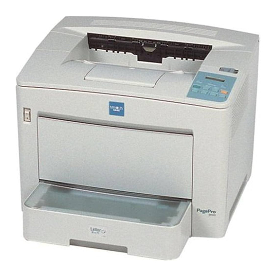
3-2. Parts identification 1 Face-down output tray 2 Power switch (S1) 3 Multipurpose paper tray (MP paper tray) 4 Universal paper cassette (first paper cassette) 5 Lower feeder unit (second through fourth media trays (optional)) 6 Control panel 7 Top rear cover release button 8 Transport unit (optional) 9 4-bin mailbox (optional) 10 Imaging cartridge (IC) - Page 33 Duplex unit (optional) Power cord socket Power cord...
-
Page 34: Component Diagram
3-3. Component diagram 4128G548AA A Paper take-up section 1 4-bin mailbox B Developing section 2 Fusing unit C Exposure section 3 Duplex unit D Drum-charging section 4 Image transfer unit E Image transfer section 5 second through fourth media trays F Fusing section 6 first paper cassette G Paper exit section... -
Page 35: Drive System
3-4. Drive system Overview of the drive system for the standard configuration • The rollers in the imaging cartridge are driven by the imaging cartridge drive motor (M2). • The rollers of the Multipurpose paper tray, first paper cassette, image transfer unit, and fusing unit are driven by the main motor (M1) via the corresponding gears. -
Page 36: Diagram Of The Drive System For The Standard Configuration
Diagram of the drive system for the standard configuration Paper output roller Heat roller PC Drum Transport roller clutch of the image transfer section Transport roller of the paper feed-in section Paper take-up roller for the first paper cassette Main motor (M1) Paper take-up roller for the multipurpose paper tray Imaging cartridge drive motor (M2) -
Page 37: Overview Of The Drive System When Options Are Installed
Overview of the drive system when options are installed • The second through fourth Lower feeder units are equipped with motors for transporting paper (paper take-up motor M1). When transporting paper from an optional paper cassette, the paper take-up roller and transport roller of the optional paper cassette are driven by the paper take-up motor installed in the paper cassette unit. -
Page 38: Electrical Components Layout
3-5. Electrical components layout Printer PWB-H PWB-O PWB-G PWB-A PWB-D Transport roller clutch of the image transfer section Paper take-up clutch for the first paper cassette Heater Humidity sensor High voltage unit Main motor Imaging cartridge drive motor Fusing fan motor Power supply unit fan motor Polygon motor Ozone fan motor... - Page 39 Paper near-empty sensor for the multipurpose paper tray Paper empty sensor for the first paper cassette Paper near-empty sensor for the first paper cassette Power supply board PWB-A Main control board PWB-D New-imaging-cartridge detection board PWB-G Toner empty detection board PWB-H Paper full detection board PWB-O...
-
Page 40: Lower Feed Unit (Optional)
Lower feed unit (optional) PWB-A Paper take-up clutch Paper take-up motor Paper sensor Paper empty sensor Paper near-empty sensor PWB-A Control board Paper size detection switch Duplex unit (optional) PWB-A Transport motor Switchback motor Duplex cover switch Duplex unit paper sensor (on PWB-A) PWB-A Control board of the duplex unit... -
Page 41: 4-Bin Mailbox (Optional)
4-bin mailbox (optional) PC10 PC11 PWB-A PC12 Transport motor PC1~4 Bin empty sensor 1~ 4 PC5~PC8 Bin full sensor 1~ 4 Lower transport sensor PC10 Upper transport sensor PC11 Cover sensor PC12 Set sensor PWB-A Control board Entrance guide switching solenoid SL2~SL4 Bin entrance switching solenoid... -
Page 42: Electrical Components Functions
3-6. Electrical components functions Printer Symbol Name Function Transport roller clutch of the Transmits the driving force from the main motor to the transport image transfer section roller of the image transfer section. Paper take-up clutch for the first Transmits the driving force from the main motor to the paper take- paper cassette up roller of the first paper cassette. -
Page 43: Lower Feed Unit (Optional)
Symbol Name Function PWB-O Control panel boad Operates the printer through the operation keys and indicates the status of the printer through the indicator and message display. Resistors Prevents poor image transfer, and prevents noise from being gener- ated. Power switch Switches on and off the power. -
Page 44: Duplex Unit (Optional)
Duplex unit (optional) Symbol Name Function Transport motor Drives the feed-back roller and the transport roller. Switchback motor Rotates the paper output roller in the printer’s fusing unit in both directions, and feeds the paper back into the duplex unit. Duplex cover switch Detects whether the duplex cover is open or closed, and stops the functions of the duplex unit if its cover is open. -
Page 45: Pwb-A (Main Control Board)
PWB-A (main control board) PJ11 PJ12 PJ13 PJ8 PJ10 PJ14 PJ17 PJ15 PJ16 PJ22 PJ21 PJ23 Fuse (rated: 15 A, 250 V) To the printer controller To the fusing section and the transport section To the relay section for the multipurpose paper tray To the lower feed unit To the new-imaging-cartridge detection board To the laser diode... -
Page 46: Pwb-D (New-Imaging-Cartridge Detection Board)
PWB-D (new-imaging-cartridge detection board) To the main control board PU1 (power supply board ) VR53 VR131 VR151 AC_L AC_N AC_L To the interlock switch 1 section primary AC_N To the interlock switch 1 section primary To the power switch section To the interlock switch 1 section secondary To the main control board To the main control board... -
Page 47: Hv1 (High Voltage Unit )
HV1 (high voltage unit ) VR101 VR403 VR402 VR201 VR401 VR302 VR501 VR301 To the bias and discharge seal To the paper take-up roller, blade 1 and blade 2 C(PJ1-CHV) To the drum-charging section To the main control board To the discharge needle To the grid mesh T(PJ1-THV) To the image transfer section... -
Page 48: Pwb-G (Toner-Empty Detection Board)
PWB-G (toner-empty detection board) PJ1 To the main control board VR1 Dial for factory adjustments (do not adjust.) (10) PWB-H (paper full detection board) PJ1 To the main control board PS3 Paper full detection sensor (11) PWB-O (control panel board) LCD1 LED3 LED2... -
Page 49: Pwb-A (Control Board Of The Lower Feed Unit)
(12) PWB-A (control board of the lower feed unit) To the main control board To the unit below To the paper near-empty sensor and the paper size detection switch To the paper jam detection sensor and the paper empty sensor To the paper take-up motor and the paper take-up clutch (13) PWB-A (DUP) (control board of the duplex unit) To the duplex unit paper sensor... -
Page 50: Pwb-A (Control Board Of The 4-Bin Mailbox)
(14) PWB-A (control board of the 4-bin mailbox) CN106 CN102 CN107 CN103 CN101 CN108 CN104 CN109 CN100 FU100 CN110 CN105 CN101 To the cover sensor, bin empty sensor 4, and bin full sensor 4 CN100 To the main control board CN102 To bin empty sensor 3 and bin full sensor 3 CN103... -
Page 51: Video Interface
3-7. Video interface Overview • The video interface consists of 12 signal wires and the power supply source, as shown below. • The signal wires include those for image data signals for transmitting images, synchronous sig- nals, signals for observing the status of the power supply, serial transmission signals for obtaining a detailed status of the printer, and reset signals. -
Page 52: Signal Descriptions
Signal descriptions There are 12 interface signals, which are divided into 5 categories according to their function. Signal Name Code Function Category /Controller /CPRDY This signal indicates that the controller is ready Signals for activating power ready to send signals to and receive them from the the video interface. -
Page 53: Timing Chart
3-8. Timing chart Pre-process sequence • The processing devices around the PC drum are started up, and the surface of the PC drum is charged with an exposable uniform electric potential. • When the pre-process sequence is finished, the operation continues with the print (print interval) sequence. -
Page 54: Print (Print Interval) Sequence
Print (print interval) sequence • In order to suppress image quality problems from occurring, the process control is switched when printing and during the print interval. Print(print interval)sequence Print Print interval Print interval Print Paper sensor of the image transfer section (PC1) Transport roller B (DC) output voltage setting B (AC) output... -
Page 55: Mechanical/Electrical
MECHANICAL/ELECTRICAL 4-1. Paper path Standard configuration • Paper can be fed into the printer either from the multipurpose tray (paper capacity: 200 sheets) or the universal paper cassette unit (paper capacity: 500 sheets). • The paper fed by the paper take-up roller is transported to the transport roller of the image transfer section →... - Page 56 (continued from previous page) 12 Paper empty sensor for the first paper cassette (PC6) 13 Paper take-up roller for the multipurpose paper tray 14 Face-down output tray 15 Paper full detection board (PWB-H) (PS3 is mounted on board)
-
Page 57: With Options Installed
With options installed • By installing up to three optional lower feeder units (paper capacity: 500 sheets), the printer can be expanded to have a maximum of 5 paper sources. • Double-sided printing is possible if the optional duplex unit is installed. •... -
Page 58: Paper Take-Up Section
4-2. Paper take-up section Multipurpose paper tray: paper take-up mechanisms & process 1 Paper take-up roller 7 Paper-separating pad 2 Paper 8 Paper empty/paper near-empty actuator 3 Paper take-up roller drive shaft 9 Paper-lifting plate 4 Unit drive gear 10 Cam 5 Paper take-up roller drive gear 11 Transport roller 6 Paper take-up solenoid (SL1) - Page 59 3. The driving force from the main motor (M1) is transmitted from the unit drive gear to rotate the paper take-up roller shaft. 1 Cam 3 Paper-lifting plate 2 Paper take-up roller 4 Multipurpose paper tray 4. The cam attached to the paper take-up roller shaft rotates, allowing the paper-lifting plate to be raised by the spring.
-
Page 60: Multipurpose Paper Tray: Paper Feed Retry Control
Multipurpose paper tray: paper feed retry control • If the paper feed operation began, but the paper take-up roller was not able to pick up the paper, instead of concluding that a paper jam occurred, the paper feed operation is performed again (paper feed retry function). -
Page 61: Multipurpose Paper Tray: Paper Empty Detection Mechanism
Multipurpose paper tray: paper empty detection mechanism • The multipurpose paper tray is equipped with a paper empty sensor (PC4), which monitors the amount of paper remaining in the multipurpose tray. • If paper is present in the tray, the actuator is pressed down by the paper. (The actuator is attached to the same shaft as the paper near-empty sensor.) 1 Paper empty actuator (toward the back) 2 Paper near-empty actuator (toward the front) -
Page 62: Multipurpose Paper Tray: Paper Near-Empty Detection Mechanism
Multipurpose paper tray: paper near-empty detection mechanism • The multipurpose paper tray is equipped with a paper near-empty sensor (PC5), which monitors the amount of paper remaining while printing. • If there is a sufficient amount of paper remaining, the actuator is pressed down by the paper. (The actuator is the same as that for the paper empty sensor.) •... -
Page 63: Universal Paper Cassette (First Paper Cassette): Paper Feed Retry Control
Universal paper cassette (first through fourth paper cassettes): paper take-up mecha- nism • When the paper cassette is inserted into the printer, the lock for the paper-lifting plate is released, and the paper-lifting plate is raised by the spring. • When the paper take-up clutch for the first paper cassette is activated, the driving force from the main motor is transmitted to the drive gear attached to the paper take-up roller shaft, and the paper take-up roller shaft is rotated. - Page 64 Lower feed unit (second through fourth paper cassettes): paper feed retry control • If the paper feed operation has already begun, but the paper take-up roller was not able to pick up the paper, instead of concluding that a paper misfeed has occurred, the paper feed operation is per- formed again (paper feed retry function).
-
Page 65: Universal Paper Cassette (First Paper Cassette): Paper Empty Detection Mechanism
Universal paper cassette (first paper cassette): paper empty detection mechanism • The paper empty sensor for the first paper cassette (PC6) is installed below the multipurpose tray to monitor the amount of paper remaining in the universal paper cassette (first paper cassette). •... -
Page 66: Universal Paper Cassette (Second Through Fourth Paper Cassettes): Paper Empty Detection Mechanism
Universal paper cassette (second through fourth paper cassettes): paper empty detection mechanism • The paper empty detection mechanism for monitoring the amount of paper remaining in the sec- ond through fourth optional paper cassettes is the same as that for the first paper cassette. •... -
Page 67: Universal Paper Cassette (First Through Fourth Paper Cassettes): Paper Near-Empty Detection Mechanism
(10) Universal paper cassette (first through fourth paper cassettes): paper near-empty detec- tion mechanism • A paper near-empty sensor (PC7) (see page 48, item #10) is installed in the mounting section of the first paper cassette in order to monitor the amount of paper remaining in the first paper cas- sette. -
Page 68: (11) Universal Paper Cassette: Paper Size Detection Mechanism
(11) Universal paper cassette: paper size detection mechanism • A paper size detection mechanism for the first paper cassette is mounted in the universal paper cassette and the mounting section of the first paper cassette. The setting of the paper size detection levers on the left side of the universal paper cassette changes according to the installation location of the paper trailing-edge guide, positioned to match the size of the paper loaded. -
Page 69: Imaging Cartridge
4-3. Imaging cartridge Overview The imaging cartridge integrates the functions for charging, developing, cleaning, toner supply and waste toner storage. Name Function PC drum A latent image is created on the surface with a laser, developing is per- formed by the developing roller, and the developed image is transferred to the surface of the paper. - Page 70 Name Function Mirror LED light from the toner empty sensor is reflected when only a small amount of toner remains. Toner hopper section Stores toner. Laser beam Path of the laser beam emitted from the print head section. Waste toner collection section Stores collected waste toner.
-
Page 71: Toner Empty Detection
Toner empty detection • The toner near-empty status is detected by the toner empty sensor LED and the photo sensor on the toner empty detection board (PWB-G). • The sensor light is emitted from the toner empty sensor LED onto the mirror in the toner hopper. PWB-G Toner empty sensor (receiver;... - Page 72 • The length of time that the photo sensor picks up the light is used to calculate the toner empty sta- tus of the hopper. • The state in which the sensor detection voltage continues to be below specification during a period of time exceeding specification and an agitation cycle is detected is considered a toner near-empty condition.
-
Page 73: Drum Charging
4-4. Drum charging • The surface of the PC drum is charged with static electricity before laser exposure. • A needle electrode/scorotron system is used as the charging method by the charger. • The needle electrode is directed at the surface of the PC drum and the DC (-) corona is discharged. •... -
Page 74: Laser Exposure
4-5. Laser exposure • A latent electrostatic image is created on the PC drum by the laser beam emitted from the print head unit. • The laser beam is emitted from the laser aperture of the print head unit into the mirror unit. •... -
Page 75: Development
4-6. Development Toner is applied to the latent electrostatic image on the PC drum and a toner image (actual image) is formed. Buffer Hopper section section 1 PC Drum 2 Discharge seal 3 Developing roller 4 Buffer section 5 Toner supply roller 6 Toner-agitating blade 7 Hopper section 8 Toner supply outlets... -
Page 76: Image Transfer
4-7. Image transfer • Image transfer is the process of transferring to paper the toner image created on the PC drum dur- ing the development process. • For the image transfer method, roller image transfer is used instead of corona image transfer. •... -
Page 77: Fusing Section
4-8. Fusing section • The toner transferred to the paper during the image transfer process is fused to the paper. • A heat roller system is used as the fusing method. The toner is fused to the paper as it is pressed between the compression roller and the heat roller, heated by the heater lamp. -
Page 78: Fusing Temperature Control Circuit
Fusing temperature control circuit • Thermistor 1 (TH1) detects the surface temperature of the fusing heat roller and inputs the analog voltage into the main control board (PWB-A). According to the temperature detected by ther- mistor 1 (TH1), the main control board (PWB-A) outputs the heater lamp ON/OFF signal to turn ON (lit) or OFF (not lit) the control of the temperature in the fusing section. -
Page 79: Overview Of Temperature Control Modes During Stand-By
Overview of temperature control modes during stand-by When warm-up is finished, but printing is not started, the temperature is controlled with the modes described below, then goes into stand-by. Mode Temperature control Mode 1 At 200 °C (392 °F) for 5 minutes (300 s) Mode 2 Lowers the temperature from 200 °C to 185 °C ( 392 °F to 365 °F) in 60 seconds Mode 3... -
Page 80: Temperature Control Modes During Printing
Temperature control modes during printing During printing, the temperature is controlled with the modes described below. Mode Temperature control Mode 1 At <X> °C for <Y> seconds Mode 2 Lowers the temperature from <X> °C to <Z> °C in 60 seconds Mode 3 <Z>... -
Page 81: Temperature Control: Software Protection
Temperature control: software protection • If thermistor 1 (TH1) detected a high-temperature malfunction but the heater (H1) is not turned OFF, the heater (H1) will be forcibly turned OFF (not lit) when the surface temperature of the heat roller exceeds 230 °C (446 °F). Temperature control: hardware protection •... -
Page 82: Paper Exit Section
4-9. Paper exit section • The paper output roller is driven by the main motor (M1) and rotated in the normal direction (paper output direction: counterclockwise). The paper is fed out into the face-down output tray with the printed side facing down. Entrance guide Paper output sensor actuator Paper output roll... -
Page 83: Paper-Full Detection Mechanism
Paper-full detection mechanism • The actuator of the paper-full detection sensor (PS3) is raised by the paper fed with the heat roller. The raised actuator allows the sensor light to pass through. • When paper is fed into the face-down output tray, the actuator returns to its original position through its own weight, interrupting the sensor light. -
Page 84: Paper Output Roller Drive-Switching Mechanism
Paper output roller drive-switching mechanism • When the optional duplex unit is installed, the paper output idler lever of the duplex unit raises the drive gear assembly of the fusing unit. The raised drive gear assembly is linked with the drive gear of the switchback motor (M2) in the duplex unit. -
Page 85: Paper-Output-Swiching Mechanism
Paper-output-swiching mechanism • When the entrance guide lever of the optional 4-bin mailbox presses down on the entrance guide of the fusing unit, the angle of the entrance guide changes. Instead of the fed paper being trans- ported by the paper output roller, it is fed out to the mailbin directed by the entrance guide. 1 Paper 2 Entrance guide lever 3 Entrance guide... -
Page 86: Duplex Section (Optional Duplex Unit)
4-10. Duplex section (optional duplex unit) Overview • The paper output roller is driven by the main motor (M1) via the duplex lever assembly, and rotated in the normal direction (paper output direction: counterclockwise). • By installing the optional duplex unit, the paper output idler lever of the duplex unit raises the drive gear assembly. -
Page 87: Single-Sided Printing Mechanism
Single-sided printing mechanism • The actuator of the paper output sensor (PC3) is raised by the paper fed by the heat roller, block- ing the sensor light. When the sensor light is interrupted, the sensor determines that paper is present. •... -
Page 88: Double-Sided Printing Mechanism
Double-sided printing mechanism • With the paper passing by the paper output sensor (PC3), the actuator of the paper output sensor (PC3) is lowered. Since the actuator no longer blocks the sensor light and allows it to pass through, the sensor detects that the paper has passed. •... -
Page 89: Sorting Section (Optional 4-Bin Mailbox)
4-11. Sorting section (optional 4-bin mailbox) Drive mechanism • If the paper arrives in front of the entrance guide in the paper feed-out section of the printer, the transport motor (M1) of the 4-bin mailbox rotates, rotating the transport roller and bin output roller via timing belts. -
Page 90: Paper-Switching Mechanism
Paper-switching mechanism • When the entrance guide switching solenoid (SL1) is activated, and the entrance guide lever of the 4-bin mailbox presses down on the entrance guide of the fusing unit, the position of the entrance guide switches. • At the same timer, the transport motor (M1) of the 4-bin mailbox starts rotating. •... -
Page 91: Bin-Switching Mechanism
Bin-switching mechanism • When the bin entrance switch solenoid (SL2 through SL4) is activated, the position of the bin entrance switch changes. • The fed paper is directed into the mailbin by the bin entrance switch. • The fed paper is transported to the mailbin by the bin output roller. Bin entrance switch Bin output roller Mailbin... -
Page 92: Fed Paper Detection Mechanism
Fed paper detection mechanism • The 4-bin mailbox is equipped with bin empty sensors (PC1~PC4), which monitor whether paper is present in the mailbins. • When there is no paper in the mailbin, the actuator is in the lowered position. A lowered actuator blocks the sensor light, enabling the bin empty sensor to determine that there is no paper in the mailbin. -
Page 93: Maintenance/Disassembly
MAINTENANCE/DISASSEMBLY 5-1. Precautions for maintenance/disassembly Precautions for disassembly Observe the following precautions whenever servicing the printer. • Be sure to unplug the printer from the outlet before attempting to service the printer. • To reassemble the printer, reverse the order of disassembly unless otherwise specified. •... -
Page 94: During Inspection The Pwbs With Mos Ics
During Inspection the PWBs with MOS ICs: • Avoid checking the IC directly with a multi-meter; use connectors on the board. • Never create a closed circuit across IC pins with a metal tool. • Where it is absolutely necessary to touch the ICs and other electrical components on the board, be sure to ground your body. -
Page 95: Cleaning Schedule
5-2. Cleaning schedule Part name Cleaning cycle Paper take-up roller (multi-purpose paper tray of the printer) When a paper misfeed occurs Image transfer roller unit (printer) When a malfunction such as poor image transferring occurs Transport roller (optional duplex unit) When a paper transport error occurs Transport roller (optional lower feed unit) When a paper transport error occurs... -
Page 96: List Of Screws Used
5-5. List of screws used Illust. Type Illust. Type Illust. Type 0509 0513 3334 Tapping screw 5129 Bolt 0601 1305 1308 5901 Screw 3403 Tapping screw Screw 1309 5902 1318 3501 3504 3524 1607 3541 Screw Tapping screw 5903 Screw 1602 3542 3544... -
Page 97: Printer Disassembly Procedures
5-6. Printer disassembly procedures Disassembly procedure chart Exhaust filter: p.96 Imaging cartridge (Pre-disassembly preparation 1): p.90 Multi-purpose(MP) paper tray Paper take-up roller of the MP paper tray (Pre-disassembly preparation 2): p.91 : p.97 Toner empty detection board (PWB-G) : p.98 Paper empty sensor (PC4) for the MP paper tray: p.99 Paper near-empty sensor (PC5) for... -
Page 98: Pre-Disassembly Preparation 1 (Removing The Imaging Cartridge)
Pre-disassembly preparation 1 (removing the imaging cartridge) Before disassembling the machine, the following units need to be removed as pre-disassembly prep- aration. • Imaging cartridge • Multi-purpose paper tray • first paper cassette • Fusing unit 1. Press the top rear cover release button, and then fully open the top cover. 2. -
Page 99: Pre-Disassembly Preparation 2 (Removing The Multi-Purpose Paper Tray)
Pre-disassembly preparation 2 (removing the multi-purpose paper tray) 1. Swing open the lower transport guide. 2. Open the multi-purpose paper tray. 3. Remove the multi-purpose paper tray stopper (three tabs). 4. Raise the tab on the locking shaft for the multi-purpose paper tray, and then pull up on the lock- ing shaft. -
Page 100: Pre-Disassembly Preparation 3 (Removing The First Paper Cassette)
Pre-disassembly preparation 3 (removing the first paper cassette) 1. Pull out the first paper cassette about 100 mm. 2. Press in the cassette release buttons on both sides of the cassette, and then remove the first paper cassette. 1 first paper cassette 2 Cassette release button... -
Page 101: Pre-Disassembly Preparation 4 (Removing The Paper-Full Detection Board)
Pre-disassembly preparation 4 (removing the paper-full detection board) 1. Remove the board holder (1 screw). 2. Remove the paper-full detection board (PWB-H) (1 screw and 1 connector). 3542 3727 Board holder Paper-full detection board (PWB-H) Note • When installing the board holder, make sure that the holder fits against the fusing unit. Fusing unit Board holder... -
Page 102: Pre-Disassembly Preparation 5 (Removing The Fusing Unit)
Pre-disassembly preparation 5 (removing the fusing unit) 1. Remove the duplex unit mounting cover (1 shoulder screw). 2. Remove the cover for the fusing unit connector (1 screw). 3. Remove the screws securing the fusing unit (2 shoulder screws). 4. Disconnect the two connectors. 3727 Shoulder screw Fusing unit connector cover... - Page 103 3541 3701 3541 Guide Pins Fusing unit Belt Note • When installing a fusing unit, be sure to install the belt. • When installing a fusing unit, make sure that the guide pins (two on the left and one on the right) on the fusing unit fit into their corresponding holders in the printer frame.
-
Page 104: Replacing The Exhaust Filter
Replacing the exhaust filter 1. Remove the exhaust filter. Exhaust filter Note • Be sure to also replace the exhaust filter when the imaging cartridge is replaced. If the printer is used with a dusty filter, the cooling efficiency of the inside of the printer is reduced, resulting in damage to or malfunction of the printer. -
Page 105: Replacing The Paper Take-Up Roller Of The Multi-Purpose Paper Tray
Replacing the paper take-up roller of the multi-purpose paper tray 1. Remove the paper take-up roller. Note • When installing a roller, make sure that the positioning pin on the back of the roller fits into the hole in the paper take-up roller drive shaft before securing the roller with the screw. 1309 Paper take-up roller drive shaft Paper take-up roller... -
Page 106: Replacing The Toner Empty Detection Board (Pwb-G)
Replacing the toner empty detection board (PWB-G) 1. Remove the toner empty detection board (PWB-G) assembly (1 screw and 1 connector). 3708 1 Toner empty detection board (PWB-G) assembly. -
Page 107: Replacing The Paper Empty Sensor (Pc4) And The Paper Near-Empty Sensor (Pc5) For The Multi-Purpose Paper Tray
(10) Replacing the paper empty sensor (PC4) and the paper near-empty sensor (PC5) for the multi-purpose paper tray 1. Remove the mounting screw securing the paper-lifting plate assembly (1 screw and 1 washer). 2. Insert flat screwdrivers between the frame of the paper tray and the paper-lifting plate (one at the left and one at the right). - Page 108 Note • When installing a paper-lifting plate, as with removing it, insert a flat screwdriver between the paper-lifting plate and the frame of the paper tray, stretch the frame of the tray, and then install the paper-lifting plate assembly. • When installing a paper-lifting plate, make sure that the end of the compression coil spring at the bottom of the paper-lifting plate is hooked onto the bracket as shown in the illustration.
-
Page 109: (11) Replacing The Paper Take-Up Solenoid (Sl1) Of The Multi-Purpose Tray
(11) Replacing the paper take-up solenoid (SL1) of the multi-purpose tray 1. Remove the paper take-up solenoid (SL1) (1 screw and 1 connector). 3501 1 Paper take-up solenoid (SL1) Note • When installing a paper take-up solenoid (SL1), make sure that the end of the solenoid actuator hooks onto the cam of the paper take-up roller drive gear. -
Page 110: (12) Replacing The Paper Empty Sensor (Pc6) For The First Paper Cassette
(12) Replacing the paper empty sensor (PC6) for the first paper cassette 1. Remove the sensor cover (1 screw). 2. Remove the paper empty sensor (PC6) for the first paper cassette (1 screw and 1 connector). 3504 3403 1 Sensor cover 2 Paper empty sensor (PC6) for the first paper cassette... -
Page 111: Replacing The Paper Take-Up Rollers And The Paper-Separating Roller For The First Paper Cassette And The Expansion Paper Cassettes
(13) Replacing the paper take-up rollers and the paper-separating roller for the first paper cassette and the expansion paper cassettes 1. Remove the paper-separating roller assembly. (2 screws). 1620 1620 1 Paper take-up roller 2 Paper-separating roller assembly. 3 Paper-separating roller Note •... - Page 112 2. Remove the coil spring. 3. Remove the collar from the shaft. 4. Pull the shaft out of the paper-separating roller assembly. 5. Remove the bracket. 1 Shaft 2 Paper-separating roller assembly. 3 Coil spring 4 Bracket 5 Collar Note •...
- Page 113 6. Remove the guide. 7. Remove the paper-separating roller (1 E-clip). 1 Paper-separating roller assembly. 2 Guide Note • Never touch the surface of the paper-separating roller or allow it to become contaminated with chemicals or toner, etc. Any scratching or contamination of the paper-separating roller will affect paper feeding.
- Page 114 8. Remove the stopper. 9. Remove the bushing. 10. Remove the paper take-up roller drive shaft from the frame of the cassette. 11. Remove the stopper. 12. Remove the paper take-up roller. 1 Paper take-up roller drive shaft 2 Paper take-up roller 3 Stopper 4 Bushing Note...
-
Page 115: Replacing The Heater (H1), Thermostat (Ts1), Thermal Fuse (Tf1), Thermistor 1 (Th1), And Heat Roller
(14) Replacing the heater (H1), thermostat (TS1), thermal fuse (TF1), thermistor 1 (TH1), and heat roller 1. Remove the drive gear assembly (1 E-clip and 1 tension coil spring). 2. Remove the rear (left) cover (1 screw and 2 shoulder screws). 1308 1 Rear (left) cover 2 Shoulder screw... - Page 116 Note • When installing the rear (left) cover, make sure that the tabs on the cover securely hook onto the frame of the fusing unit. 5. Peel off the seal. 6. Remove the front cover (3 screws and 1 connector). 7.
- Page 117 9. Remove the thermal fuse (TF1) (2 screws). 10. Remove the thermostat (TS1) (2 screws). 11. Remove the thermistor 1 (TH1) (1 screw). 3709 1305 1305 1305 1 Thermistor 1 (TH1) 2 Thermal fuse (TF1) 3 Thermostat (TS1) Note • When installing the front cover, make sure that the tabs on the cover securely hook onto the frame of the fusing unit.
- Page 118 12. Remove the screw securing the heater (H1) (1 screw). 13. Remove the heater holding bracket (1 screw). 14. Pull out the heater (2 screws). 1305 1305 1 Heater (H1) 2 Heater holding bracket Note • When handling the heater (H1), touch only the ceramic ends of the heater. •...
- Page 119 15. Remove the idler gear (1 E-clip). 16. Remove the heater holder (1 screw). 17. Remove the docking gear (1 E-clip). 1308 1 Docking gear 2 Heater holder 3 Idler gear 18. Remove the pressure springs (front and rear) (pressure shoulder springs with 1 washer each). 19.
- Page 120 20. Remove the rear movable guide (2 shoulder screws). 1 Rear movable guide 2 Shoulder screw...
- Page 121 21. Remove the paper output roller (2 E-clips and 2 bushings). 22. Open the thermal insulating plate. 23. Remove the cover (3 screws). 24. Remove the paper output guide assembly (1 screw). 1308 1308 1308 3716 1 Cover 2 Thermal insulating plate 3 Paper output guide assembly 4 Paper output roller...
- Page 122 25. Remove the heat roller (1 heat roller stop ring, 1 bushing, 1 bearing, 1 insulating material, and 1 thermal insulating plate). 26. Remove the compression roller. 1 Heat roller stop ring 2 Bushing 3 Compression roller 4 Insulating bushing 5 Bearing 6 Heat roller gear 7 Thermal insulating plate...
-
Page 123: (15) Replacing The Paper Output Sensor (Pc3) Of The Fusing Section
(15) Replacing the paper output sensor (PC3) of the fusing section 1. Remove the rear cover of the fusing unit (1 screw and 1 shoulder screw). 2. Remove the sensor stopper. 3. Remove the paper output sensor cover (1 screw). 4. -
Page 124: (16) Replacing The Image Transfer Roller Unit
(16) Replacing the image transfer roller unit 1. Raise the guides on the two ends of the image transfer roller. 2. Hold the two guides, and remove the image transfer roller unit. 1 Image transfer roller guides 2 Image transfer roller unit Note •... -
Page 125: Replacing The New-Imaging-Cartridge Detection Board (Pwb-D)
(17) Replacing the new-imaging-cartridge detection board (PWB-D) 1. Remove the PWB-D assembly (2 shoulder screws, 2 compression coil springs and 1 connector). 2. Remove the new-imaging-cartridge detection board (PWB-D) (1 holding bracket, 1 screw and 1 connector). 3708 1 PWB-D assembly. 2 Shoulder screw 3 New-imaging-cartridge detection board (PWB-D) 4 Holding bracket... -
Page 126: Removing The Outer Covers
(18) Removing the outer covers 1. Remove the right cover (4 screws). 2. Remove the top front cover (3 screws and 1 connector). 3803 3541 3541 3541 3541 3541 3541 1 Top front cover 2 Right cover Note • When installing the covers, be sure to first insert the tabs on the cover into the printer frame before putting the cover back into place. - Page 127 3. Remove the rear cover (8 screws). 4. Remove the left cover (4 screws). 5. Remove the front cover (2 screws). 3541 3541 3541 3541 3541 3541 3544 3541 3541 1 Front cover 2 Rear cover 3 Left cover Note •...
-
Page 128: (19) Replacing The Control Panel
(19) Replacing the control panel 1. Remove the control panel (2 screws). 3727 3727 1 Control panel... -
Page 129: (20) Removing The Shield
(20) Removing the shield 1. Remove the shield (16 screws). 3501 3501 3501 3501 3501 1 Shield Note • When installing the shield, be sure to first insert the positioning hooks on the shield into the slots in the frame. 1 Positioning hooks on the shield... -
Page 130: Replacing Thermistor 2 (Th2)
(21) Replacing thermistor 2 (TH2) 1. Remove thermistor 2 (TH2) (1 screw and 1 connector). 3914 Thermistor 2 (22) Replacing the humidity sensor (HS1) 1. Remove the mounting screw securing the humidity sensor (HS1) and the sensor holder (1 screw). 2. -
Page 131: (23) Replacing The Power Supply Unit Fan Motor
(23) Replacing the power supply unit fan motor 1. Open the wire holder, and remove the wires (1 wire holder). 2. Remove the power supply unit fan motor (M4) (2 screws and 1 connector). 3334 3334 1 Power supply unit fan motor (M4) 2 Wire holder Note •... -
Page 132: Replacing Interlock Switch 1 (S2)
(24) Replacing interlock switch 1 (S2) 1. Open the wire holders, and remove the wires (2 wire holders). 2. Remove the flexible wires from the wire guides on the interlock switch 1 assembly (3 guides). 3. Remove the interlock switch 1 assembly (2 screws and 3 connectors). 3504 3504 1 Wire guide... -
Page 133: Replacing The Main Control Board (Pwb-A)
(25) Replacing the main control board (PWB-A) 1. Remove the main control board (PWB-A) (4 screws, 18 connectors, and 1 card cable). 3501 3501 3501 3501 1 Main control board (PWB-A) 2 Card cable Note • When disconnecting the card cable, first release the connector lock, and the pull out the cable. - Page 134 Note • When disconnecting the connectors attached to the main control board (PWB-A), be careful not to pull out the expansion cassette connectors shown in the illustration. • The expansion cassette connectors, shown in the illustration, are not the type that can be pulled up.
-
Page 135: (26) Replacing The Print Head Unit
(26) Replacing the print head unit WARNING Do not replace the print head unit with the printer turned on. Exposure to the laser beam may result in blindness. The print head unit must not be disassembled or adjusted. Exposure to the laser beam may result in blindness. -
Page 136: Replacing The Ozone Fan Motor (M6)
(27) Replacing the ozone fan motor (M6) 1. Open the wire holder, and remove the wires (1 wire holder). 2. Remove the ozone fan motor (2 screws and 1 connector). 1 Mounting screw 2 Ozone fan motor (M6) 3 Wire holder Note •... -
Page 137: Replacing The Power Supply Board (Pu1)
(28) Replacing the power supply board (PU1) 1. Remove the shield (7 screws). 2. Open the wire holders, and remove the wires (3 wire holders). 3. Remove the power supply assembly (3 screws and 1 connector). 3546 1305 3546 3501 3501 1305 1 Shield... -
Page 138: Replacing The High Voltage Unit (Hv1)
(29) Replacing the high voltage unit (HV1) 1. Open the wire holders, and remove the wires (2 wire holders). 2. Remove the high voltage unit (HV1) (3 screws and 3 connectors). 3. Remove the protective plate. 3501 3501 3501 1 High voltage unit (HV1) 2 Protective plate Note •... -
Page 139: Replacing The Power Switch (S1)
(30) Replacing the power switch (S1) 1. Remove the primary harness cover (2 screws). 2. Remove the power switch (S1) (4 connectors). 3501 3501 1 Power switch (S1) 2 Primary harness cover Note • When installing a power switch (S1), be extremely careful to install it as shown in the illustration. -
Page 140: Replacing Interlock Switch 2 (S3)
(31) Replacing interlock switch 2 (S3) 1. Remove the switch cover. 2. Open the wire holders, and remove the wires (2 wire holders). 3. Remove interlock switch 2 (S3) (4 connectors). 1 Primary harness cover 2 Interlock switch 2 (S3) Note •... -
Page 141: Replacing The Main Motor (M1) And Imaging Cartridge Drive Motor (M2)
(32) Replacing the main motor (M1) and imaging cartridge drive motor (M2) 1. Open the wire holders, and remove the wires (1 wire holder each). 2. Remove the main motor (M1) and imaging cartridge drive motor (M2) (4 screws each). 3501 3501 3501... -
Page 142: Replacing The Paper Size Detection Switch (S4), The Paper Empty Sensor (Pc6), And The Paper Take-Up Clutch (Cl2) For The First Paper Cassette
(33) Replacing the paper size detection switch (S4), the paper empty sensor (PC6), and the paper take-up clutch (CL2) for the first paper cassette 1. Open the wire holders, and remove the wires (5 wire holders). 2. Disconnect the connectors for the paper take-up clutch (CL2) and the paper size detection switch (S4) for the first paper cassette (2 connectors). - Page 143 7. Remove the actuator. 8. Remove the sensor stopper. 9. Remove the paper near-empty sensor (PC7) for the first paper cassette. 10. Remove the paper size detection switch (S4) for the first paper cassette. 1 Actuator 2 Paper near-empty sensor for the first paper cassette (PC7) 3 Paper size detection switch for the first paper cassette (S4) 4 Paper size detection assembly.
-
Page 144: Replacing The Fusing Fan Motor (M3)
(34) Replacing the fusing fan motor (M3) 1. Open the wire holders, and remove the wires (9 wire holders). 2. Remove the fan motor assembly (4 screws and 4 connectors). 3. Remove the fusing fan motor (M3) (2 screws). 3716 3716 1 Fan assembly. -
Page 145: Replacing The Transport Roller Clutch (Cl1) And The Paper Sensor (Pc1) Of The Image Transfer Section
(35) Replacing the transport roller clutch (CL1) and the paper sensor (PC1) of the image transfer section 1. Remove the image transfer unit. 2. Remove the lower transport guide. 3. Remove the transport roller clutch (CL1) (1 E-clip and 1 bushing). 1 Image transfer unit 3 Transport roller clutch (CL1) 2 Bushing... - Page 146 4. Remove the sensor assembly (2 screws). 5. Remove the paper sensor (PC1) of the image transfer section (1 sensor stopper). 6. Remove the actuator and the torsion coil spring. 1 Sensor stopper 2 Paper sensor of the image transfer section (PC1) 3 Sensor assembly 4 Actuator Note...
-
Page 147: Duplex Unit Disassembly Procedures
5-7. Duplex unit disassembly procedures Replacing the transport motor (M1), the switchback motor (M2), the control board (PWB-A), and the duplex cover switch (PC1) 1. Remove the drive cover (2 screws). 2. Remove the transport motor (M1) (2 screws and 1 connector). 3. - Page 148 Note • When installing a control board (PWB-A), make Duplex unit Actuator sure that the end of the actuator is positioned at paper sensor about the center of the duplex unit paper sensor (PC2) (PC2) on the board. • When installing a duplex cover sensor (PC1), be sure to affix the sensor stopper. •...
-
Page 149: 500-Sheet Lower Feed Unit Disassembly Procedures
5-8. 500-sheet lower feed unit disassembly procedures Replacing the control board (PWB-A) 1. Remove the bracket assembly (3 screws). 2. Remove the control board (PWB-A) (4 screws and 5 connectors). 3501 3501 3501 3501 3501 3501 3501 1 Bracket assembly. 2 Control board (PWB-A) 3 Drawer connector Note... -
Page 150: Replacing The Paper Take-Up Clutch (Cl1) And The Paper Take-Up Motor (M1)
Replacing the paper take-up clutch (CL1) and the paper take-up motor (M1) 1. Remove the paper take-up assembly (6 screws). 2. Remove the motor assembly (5 screws, 2 E-clips, 1 bushing, and 1 gear). 3. Remove the paper take-up clutch (CL1) (1 E-clip). 4. -
Page 151: Replacing The Paper Sensor (Pc1)
Replacing the paper sensor (PC1) 1. Remove the switch cover (1 screw). 2. Remove the paper sensor (PC1) (1 sensor stopper and 1 connector). 3501 1 Switch cover 2 Paper sensor (PC1) Note • When installing the paper sensor (PC1), make Paper sensor Bracket sure that the tab of the detection switch extends from... -
Page 152: Replacing The Paper Empty Sensor (Pc2)
Replacing the paper empty sensor (PC2) 1. Remove the sensor cover (2 screws). 2. Remove the paper empty sensor (PC2) (1 screw and 1 connector). 3501 3501 3501 1 Paper empty sensor (PC2) 2 Sensor cover Note • When installing the sensor cover, be sure not to pinch the harness of the sensor. Sensor cover Harness... - Page 153 Replacing the paper size detection switch (S1) and the paper near-empty sensor (PC3) 1. Remove the paper size detection assembly (1 screw and 2 connectors). 2. Remove the bracket (1 screw). 3. Remove the actuator. 4. Remove the paper size detection switch (S1). 5.
-
Page 154: 4-Bin Mailbox Disassembly Procedures
5-9. 4-bin mailbox disassembly procedures Replacing the lower transport sensor (PC9) 1. Remove the tray (4 screws). 2. Remove the tray cover. 3. Remove the sensor bracket (1 screw). 4. Remove the lower transport sensor (PC9). 4501 1 Sensor bracket 2 Tray cover 3 Lower transport sensor (PC9) Note... -
Page 155: Replacing The Sensors Of Mailbins 1 And 3
Replacing the sensors of mailbins 1 and 3 Note • The replacement procedure for the sensors of mailbins 1 and 3 is the same; only the part names differ. 1. Remove the tray (4 screws). 2. Remove the tray cover. 3. -
Page 156: Replacing The Sensors Of Mailbin 2
Replacing the sensors of mailbin 2 1. Remove the tray (4 screws). 2. Remove the tray cover. 3. Remove the sensor bracket (1 screw). 4. Remove bin empty sensor 2 (PC2). 5. Remove bin full sensor 2 (PC6). 6. Remove the upper transport sensor (PC10). 4501 1 Upper transport sensor (PC10) 2 Bin empty sensor 2 (PC2) -
Page 157: Replacing The Sensors Of Mailbin 4 And The Cover Sensor
Replacing the sensors of mailbin 4 and the cover sensor 1. Remove the tray (4 screws). 2. Remove the right cover (1 screw). 3. Remove the left cover (1 screw). Note • When removing the left and right covers, first remove the screw, and then pull the covers out and remove the tabs from the mailbin frame. - Page 158 Note • When installing the top cover, make sure that it is under the left and right covers. • When installing the left and right covers, make sure that the tabs on the covers fit into the slots in top the cover.
-
Page 159: Replacing The Set Sensor (Pc12) And The Control Board (Pwb-A)
Replacing the set sensor (PC12) and the control board (PWB-A) 1. Remove the set sensor cover. 2. Remove the docking lever assembly (2 screws and 2 connectors). 3. Remove the set sensor (PC12) (1 connector). 5902 5902 1 Docking lever assembly 2 Set sensor (PC12) 3 Set sensor cover 4. -
Page 160: Replacing The Transport Motor (M1) And The Solenoids
Replacing the transport motor (M1) and the solenoids 1. Remove the bracket for the motor and solenoids (4 screws, 1 drive belt, 4 torsion coil springs and 1 C-clip). 2. Remove the transport motor (M1) (2 screws). 3. Remove the entrance guide switching solenoid (SL1) (2 screws). 4. - Page 161 Note • When installing the bracket for the motor and solenoids, perform the following gear adjustment. • Assemble gears A, B and C as shown in the illustration, and then secure the shaft of gear A at the entrance guide switching solenoid (SL1) with the C-clip. Entrance guide switching...
- Page 162 • Check the orientation of the bracket with gear C. (The angle of the section of gear C shown in the illustration with respect to the bracket should be adjusted to 90°to 94°.) 90°~94° Score mark • If the angle of gear C is out of specification (90°~94°), loosen the 2 gear bracket-securing screws, and then adjust the installation position of the gear bracket so that the angle of gear C is within specifications.
-
Page 163: Adjustment
ADJUSTMENT 6-1. Adjustment of image registration • After the Main Control Board (Controller board) is replaced, be sure to print of an sample image. If the starting position of the image (registration gap (d)=4mm) in the sub-scanning direction is not suitable, adjust the gap by following the procedure described below. 1. -
Page 165: Troubleshooting
TROUBLESHOOTING 7-1. Paper misfeed detection Detecting paper remaining in the machine According to the signal (H or L) from the following sensors, the printer determines whether or not paper remains in the machine. 1. Printer: • Paper sensor of the image transfer section (PC1) •... -
Page 166: Operation When A Paper Misfeed Is Detected
Operation when a paper misfeed is detected When a paper misfeed is detected, the following elements are stopped. 1. Printer: • Main motor (M1) • Imaging cartridge drive motor (M2) 2. Second through fourth media trays (optional) • Paper take-up clutch (CL1) 3. - Page 167 8. If the duplex unit paper sensor (PC2) does not detect the trailing edge of the paper within a set length of time from the moment that the paper output sensor (PC3) of the printer detects the trailing edge of the paper while feeding the paper the second time during double-sided printing. 9.
-
Page 168: Procedure For Resetting After A Paper Misfeed Is Detected
Procedure for resetting after a paper misfeed is detected To cancel a paper misfeed error, remove the misfed paper, and then open and close the top rear cover, the duplex unit cover or the 4-bin mailbox cover, or remove and insert the paper cassette. However, if a paper misfeed occurs where the paper remains in the machine, the reset procedure dif- fers according to the location of the paper misfeed. -
Page 169: Malfunction Detection
7-2. Malfunction detection When any of the following malfunctions are detected, all driving units are stopped, and the corre- sponding hardware error appears on the control panel. Laser malfunction - Service Call 10 H-Sync 1. If the -SOS signal is not detected within 200 ms after laser emission begins after the polygon motor (M5) is activated. -
Page 170: Fusing Fan Motor Malfunction Service Call 0B Internal Fan
Fusing fan motor malfunction Service Call 0B Internal Fan 1. If the FUSER_FAN_LOCK signal is set to "H" for 1 s while the fusing fan motor (M3) is rotat- ing. 2. If the FUSER_FAN_LOCK signal is set to "L" for 1 s while the fusing fan motor (M3) is stopped. -
Page 171: Troubleshooting For Paper Misfeeds
7-3. Troubleshooting for paper misfeeds Paper misfeed when the power switch is turned on Check Remedy → Is the paper in the machine? • Remove all paper remaining in the machine. ↓ → Are the actuators of the paper sensor (PC1) •... -
Page 172: Paper Misfeed Between The Transport Section And The Paper Feed-Out Section
Paper misfeed between the transport section and the paper feed-out section Check Remedy → Is the image transfer roller deformed, • Replace the image transfer roller unit. scratched, or dirty with paper dust or toner? (Has it reached the end of its service life?) ↓... -
Page 173: Paper Jam Display Messages And Associated Sections
Paper jam display messages and associated sections A Paper Take-up B Image Transfer C Fusing Section D Paper Exit E Duplex F Mailbin Paper Jam Message Location to be checked 1 Media Jam MPT 2 Media Jam Upper tray 3 Media Jam Optional 1 tray 4 Media Jam Optional 2 tray 5 Media Jam Optional 3 tray 6 Media Jam Transportr... -
Page 174: Troubleshooting For Operation Malfunctions
7-4. Troubleshooting for operation malfunctions Hardware errors Check Remedy → Did the error appear after warm-up was • Replace thermistor 1 (TH1) or the fusing unit. • Replace the main control board (PWB-A). completed? ↓ → After turning on the printer, does the rotat- •... -
Page 175: Image Quality Troubleshooting
7-5. Image quality troubleshooting When an image problem occurs, exchange the Imaging Cartridge a new one and determine whether the cause of the problem is due to the cartridge or something else in the printer. If the problem still occurs, please use the following chart to help determine the defective unit (mm) Pitch Possible defective part... - Page 176 Symptom Cause Remedy Blank print No imaging cartridge installed • Install the imaging cartridge. No toner in imaging cartridge • Replace the imaging cartridge. Defective PC drum (end of service • Replace the imaging cartridge. life) Improper laser exposure • Replace the print head unit. •...
- Page 177 Symptom Cause Remedy Toner smudges on backside Dirty heat roller • Replace the heat roller. • Replace the fusing unit. of paper Dirty image transfer roller • Replace the image transfer roller unit. Dirty paper transport path • Clean the paper path within the printer.
- Page 178 Symptom Cause Remedy White/Black lines and bands Scratched PC drum • Replace the imaging cartridge. Defective print head • Replace the print head unit. • Replace the print head section. Offset image Defective fusing roller • Replace the fusing roller. •...
-
Page 179: Index
INDEX Acoustic noise 21 Adjustment of image registration 155 Biasing 65 Bin empty sensors (PC1~PC4) 84 Bin entrance switch solenoid (SL2 through SL4) 83 Bin full sensors (PC5~PC8) 84 Bin-switching 83 Black print 168 Blank print 168 Cautions 4 Dis/Reassembly 9 Handling of PWBs 9 Imaging Cartridge 10 Laser Beam 5... - Page 180 Duplex unit specifications 23 Dimensions 23 Media sizes 23 Media types 23 Weight 23 Electrical components functions 34 Electrical components layout 30 4-bin mailbox 33 Duplex unit 32 Lower feed unit 32 Printer 30 Entrance guide switching solenoid (SL1) 82 Error Codes Service Call 02 I/F Communication 162 Service Call 08 Main Motor 162...
- Page 181 Heat roller 69 Heater lamp 69 Heater lamp control 70 High-temperature error 161 HV1 (high voltage unit ) 39 Image quality troubleshooting 167 Black print 168 Blank print 168 Foggy background 169 Low image density 169 Offset image 170 Toner smudges on backside of paper 169 White spots 168 White/Black lines and bands 170 Image registration 155...
- Page 182 Mailbox 81 Bin-switching mechanism 83 Drive mechanism 81 Fed paper detection mechanism 84 Full mailbin detection mechanism 84 Paper-switching mechanism 82 Mailbox disassembly procedures 146 Control board (PWB-A) 151 Cover sensor 149 Lower transport sensor (PC9) 146 Sensors of mailbin 2 148 Sensors of mailbin 4 149 Sensors of mailbins 1 and 3 147 Set sensor (PC12) 151...
- Page 183 Needle electrode 65 No power 166 Offset image 170 Operation malfunctions Hardware errors 166 No power 166 Overheat error 161 Overheat hardware protection 73 Overheat protection 73 Overheat software protection 73 Overview of the drive system 27 OZON_FAN_LOCK_PULSE signal 161 Ozone fan motor malfunction 161 Paper capacity 20 Paper empty detection 57...
-
Page 184: Housing
Paper-full detection sensor (PS3) 75 Paper-output-switching mechanism 77 Paper-switching mechanism 82 PC Drum 20 Polygon motor malfunction 161 Polygon_M_Lock signal 161 Power supply unit fan motor malfunction 161 Print mechanism, duplexer 80 Print resolution 19 Printer disassembly procedures Control panel 120 Fusing fan motor (M3) 136 Heat roller 107 Heater (H1) 107... - Page 185 Thermostat (TS1) 107 Toner empty detection board (PWB-G) 98 Transport roller clutch (CL1) 137 Printer timing 45 PSU_FAN_LOCK_PULSE signal 161 PU1 (power supply board ) 38 PWB-A (control board of the 4-bin mailbox) 42 PWB-A (control board of the lower feed unit) 41 PWB-A (DUP) (control board of the duplex unit) 41 PWB-A (main control board) 37 PWB-D 38...
- Page 186 Toner cartridge operation 67 Toner empty detection 63 Toner empty detection board (PWB-G) 63 Toner empty status 64 Toner smudges 169 Tools 87 Transfer 68 Troubleshooting 157 Image quality 167 Malfunction detection 161 Operation malfunctions 166 Paper misfeed detection 157 Paper misfeeds 163 Universal paper cassette Paper empty detection mechanism 57, 58...
- Page 187 #PagePro 9100 PARTS LIST...
- Page 188 "SCREWS AND WASHERS". Please check these "four-digit" numbers with the part numbers ("ten-digit" numbers) which should be used for ordering the part. All part numberslisted in this Parts List consist of ten digits. However, you must add the special MINOLTA-QMS “ 831” prefix to the beginning of the part number when ordering a part.
- Page 189 Parts List SFIX CHART VOLTAGE FREQUENCY VOLTAGE FREQUENCY SFIX No. COUNTRY PAPER SIZE SFIX No. COUNTRY PAPER SIZE (Hz) (Hz) JAPAN 100V 50/60 METRIC USA/CANADA 120V INCH EUROPE 220-240V METRIC CONTENTS HOUSING • • • • • • • • • • • • • • • • • • • • • • • • • • • • • • • • • • • • • • • • • • • • • • • • • • • • • • • • • • • • • • • • • • • • • • • • • 176 FRAME (A)•...
- Page 190 HOUSING PagePro 9100 3541 3727 3727 3541 3734 3541 3730 3541 3727 3541 3730 3803 3701 9109 3734...
- Page 191 INDEX PART NO. PART NAME INDEX PART NO. PART NAME 4128-1003-03 COVER 4128-1002-01 COVER 4128-5814-01 EARTH GROUND 4128-1005-01 FRONT COVER 4128-1019-01 COVER 4128-1006-01 TRAY 4128-1010-01 COVER 4128-1012-01 TRAY 4128-1221-01 SHOULDER SCREW 4128-1014-02 LEVER 4128-1026-01 COVER 4128-1007-01 TRAY 4128-1008-02 REAR COVER 0951-7105-03 LABEL 4128-1004-01...
-
Page 192: Frame (A)
FRAME (A) PagePro 9100 3501 3501 2911 3501 3546 3541 3546 3501 3501 1305 3504 3504 4021 3708 1318 3546 3501 3501 3501 3504 3547 3906... - Page 193 INDEX PART NO. PART NAME INDEX PART NO. PART NAME 4128-1222-01 SHOULDER SCREW 9326-1910-21 FERRITE CORE 4128-6807-01 WIRE HARNESS ASSY 4128-2019-01 RUBBER FOOT 4128-2032-01 GUIDE 4128-7312-01 LABEL 4128-2211-02 BRACKET 4128-2212-01 SHIELD 4128-2031-01 REGULATING PLATE 4128-0532-02 PRINT HEAD UNIT (P/H) 4128-0551-01 PRINT HEAD UNIT 4128-1978-01 PRESSURE SPRING...
-
Page 194: Frame (B)
FRAME (B) PagePro 9100 3501 3541 3501 3541 1305 3541 3501 3541 1305 3501 3501 3501 PWB-A 3501 4011 3524 3501... - Page 195 INDEX PART NO. PART NAME INDEX PART NO. PART NAME 4128-2272-01 BRACKET 4128-2270-01 BRACKET 4128-2263-01 RAIL 4128-2264-02 BRACKET 4128-2262-02 BRACKET 4128-2043-01 SEAL 4128-3051-01 STOPPER 9384-1900-55 PWB SUPPORT 9.53H 9346-3000-11 FUSE (F1) 4128-2269-01 EARTH GROUND 9372-5910-11 HUMIDITY CONVERTION EL. HUMIDITY (HS1) 9372-2710-21 THERMISTOR THERMISTOR (TH2)
-
Page 196: Frame (C)
FRAME (C) PagePro 9100 9302 3734 9302 9302 0509 0509 3334 3929 3716 9301 3708 3504 3708 3504 3708 3734 9302 3708 9302 3708 9301 3708 3708 9302 3708 3734 3501 3501... - Page 197 INDEX PART NO. PART NAME INDEX PART NO. PART NAME 9313-1001-01 FAN MOTOR OZONE (M4.6) 4128-3105-14 GUIDE 4128-2042-03 LEVER 4128-6203-02 HV TRANSFORMER HIGH-VOL. (HV1) 4011-2037-01 TORSION SPRING 4128-2224-01 PROTECTION 9331-2710-11 MICRO SWITCH INTERLOCK (S2) 0993-2045-01 SCREW 4128-0751-01 GUIDE ASSY 4128-2026-01 TENSION SPRING 4128-3143-01 GEAR...
-
Page 198: Fusing Section (A)
FUSING SECTION (A) PagePro 9100 3716 9303 FRU UNIT FIG.6 1607 3708 1607 3708 1305 3204 1305 1308 1208 3709 1208 1305 1607 1305 1305... - Page 199 INDEX PART NO. PART NAME INDEX PART NO. PART NAME 4128-5761-01 SHOULDER SCREW 4128-5724-01 ACTUATOR 0972-5519-01 TORSION SPRING 4002-0902-01 PHOTO INTERRUPTER P.OUTPUT (PC3) 9372-2710-12 THERMISTOR THERMISTOR (TH1) 9346-3810-31 THERMAL FUSE THERMAL (TF1) 9334-1000-21 THERMAL SWITCH THERMOSTAT (TS1) INDEX PART NO. PART NAME SFIX 4570-111...
-
Page 200: Fusing Section (B)
FUSING SECTION (B) PagePro 9100 3730 PWB-H 3542 1308 8301 8405 9107 1305 9107 1308 8405 3716 9107 3716 9107 9105 1308 9107 9107 1308 1607 1607... - Page 201 INDEX PART NO. PART NAME INDEX PART NO. PART NAME 4128-5801-01 ROLLER 4128-5851-02 LEVER 4128-5708-01 BALL BEARING 4128-5852-01 WEIGHT 0993-3220-01 ROLL 4128-5853-01 GUIDE 4128-5757-01 TENSION SPRING 4128-0111-01 PWB ASSY P.EXIT (PWB-H) 4128-5728-02 SEPARATOR 4128-5770-01 PRESSURE SPRING 1164-5772-01 STOP RING 4128-5771-01 CUSHION 1164-5709-01 GEAR...
-
Page 202: Paper Transport Section
PAPER TRANSPORT SECTION PagePro 9100 3708 9109 9109 3716 3708 9109 9109 9109 CRU UNIT... - Page 203 INDEX PART NO. PART NAME INDEX PART NO. PART NAME 9313-1001-01 FAN MOTOR FUSING COOL (M3) 4128-3507-01 ROLLER 0993-2045-01 SCREW 4128-0365-01 TRANSPORT UNIT 0951-7105-03 LABEL 4002-0902-01 PHOTO INTERRUPTER TRANSFER (PC1) 4128-3504-01 TORSION SPRING 4128-3503-01 ACTUATOR 1164-4206-02 BUSHING 9322-1000-31 CLUTCH TRANSPORT (CL1) 4128-3509-01 BUSHING...
-
Page 204: Drive Section
DRIVE SECTION PagePro 9100 PWB-D 3708 3708 3708 3546 9301 3501 3708 9301 3708 3708 3501 3501... - Page 205 INDEX PART NO. PART NAME INDEX PART NO. PART NAME 4128-0104-01 PWB ASSY DETECT (PWB-D) 4128-2518-01 GEAR 9332-1710-41 SWITCH INTERLOCK (S3) 9314-2001-01 MOTOR IC DRIVE (M2) 9314-2000-91 MOTOR MAIN (M1) 9322-1000-21 CLUTCH P.TAKE-UP (CL2) 4128-3132-01 GEAR 4128-0753-01 LOCK SHAFT ASSY 4128-3122-02 ACTUATOR 0990-6304-02...
-
Page 206: Multiple Purpose Tray
MULTIPLE PURPOSE TRAY PagePro 9100 3708 04 05 3708 PWB-G CRU UNIT 9112 0601 1309 3708 3734 3708 3708 3708 3501 3708 3708 3403 3708 3734 3504 3708... - Page 207 INDEX PART NO. PART NAME INDEX PART NO. PART NAME 4128-0107-03 PWB ASSY T.EMPTY (PWB-G) 4128-2512-01 GEAR 4128-3007-01 4128-3015-01 FRICTION SHEET 4122-3006-01 ROLL 4128-3048-03 REGULATING PLATE 0957-3040-01 4128-3047-03 REGULATING PLATE 4128-3002-01 ROLLER 4128-3034-13 BRAKE 4128-0754-01 SEPARATOR ASSY 4128-0403-01 MULTIPLE TRAY ASSY 4128-3030-01 GUIDE 4128-3050-01...
-
Page 208: Universal Cassette
UNIVERSAL CASSETTE PagePro 9100 3504 3504 1620 9303 9303 9303 1620 3704 3708 3708 3708 3708 3708 9301 9301 9301 9102 3708 3708 3708... - Page 209 INDEX PART NO. PART NAME INDEX PART NO. PART NAME 0978-3811-01 FRICTION SHEET 9384-1921-31 WIRING SADDLE 17.3H 4658-0151-01 ROLLER ASSY SEPARATE 9384-1310-11 WIRING SADDLE 5.2H 4128-3215-01 STOP RING 9384-1310-81 WIRING SADDLE 6.4H 1274-3603-01 BUSHING 9384-2010-21 EDGE COVER 8.5H 1710528-001 ROLLER TRANSFER (CRU) 9384-2910-31...
- Page 210 DUPLEX UNIT (OPTION) Duplex PagePro 9100 9302 9302 3708 9107 9302 9302 3907 9302 3708 3547 3708 3504 3104 PWB-A 3708 9302 3708 3504 3104 3504 3727...
- Page 211 INDEX PART NO. PART NAME INDEX PART NO. PART NAME 4497-3106-03 PRESSURE SPRING 4564-3803-02 ROLLER 4564-3823-01 GUIDE 4564-3824-01 TORSION SPRING 4497-3152-01 GUIDE 4603-3218-01 SPRING 4497-3113-02 ROLLER 4603-3207-01 ROLL 4497-3116-01 ROLL 4497-3122-01 GEAR 4497-3153-01 GUIDE 4564-3829-01 CUSHION 4497-3109-02 STOPPER 4564-3830-02 FILTER 4564-3815-01 RING 9314-1000-91...
-
Page 212: Housing (Option)
UNIVERSAL CASSETTE (A) (OPTION) Lower Feeder Unit PagePro 9100 3546 3501 PWB-A 3501 3708 3708 3734 3717 3504 3501 3501 3734 3708 3708 3708 3717 3717 3705 3717 3708... - Page 213 INDEX PART NO. PART NAME INDEX PART NO. PART NAME 4565-0101-02 PWB ASSY CONTROL (PWB-A) 4498-3402-01 RUBBER FOOT 9332-1000-11 PUSHBUTTON SWITCH P.SIZE DETECT (S1) 4128-2032-01 GUIDE 4128-1225-01 HANDLE 4128-3122-02 ACTUATOR 4002-0902-01 PHOTO INTERRUPTER P.NEAR EMPT (PC3) 4565-3303-01 COUPLING 4565-3304-02 SCREW INDEX PART NO.
- Page 214 UNIVERSAL CASSETTE (B) (OPTION) Lower Feeder Unit PagePro 9100 3501 9302 9115 9302 3501 9115 0501 9301 0513 9115 0509 9115 9115 3501 3708 3501 3501 3501 9301 9301 9302 9301 9302 1318 9301 9301...
- Page 215 INDEX PART NO. PART NAME INDEX PART NO. PART NAME 4658-3504-01 GEAR 4002-0902-01 PHOTO INTERRUPTER P.SENSOR (PC1) 4128-3110-01 BUSHING 4658-3506-01 TENSION SPRING 4658-3514-01 ROLL 4658-3513-01 ROLLER 4565-3311-01 ROLLER 1200-3131-03 BUSHING 4565-3328-01 GEAR 4128-3142-01 TORSION SPRING 4565-3325-01 GEAR 9314-1000-11 MOTOR P.TAKE-UP (M1) 1200-3131-07 BUSHING...
- Page 216 UNIVERSAL CASSETTE (C) (OPTION) Lower Feeder Unit PagePro 9100 3504 3504 1620 9303 9303 9303 1620 3704 3708 3708 3708 3708 3708 9301 9301 9301 9102 3708 3708 3708...
- Page 217 INDEX PART NO. PART NAME INDEX PART NO. PART NAME 0978-3811-01 FRICTION SHEET 9384-1311-11 CABLE TIE 104L 4658-0151-01 ROLLER ASSY 9384-1811-01 CORD CLAMP 4128-3215-01 STOP RING 4128-3243-01 PRESSURE SPRING 1274-3603-01 BUSHING 1710528-001 ROLLER TRANSFER (CRU) 4658-3028-01 DRUM 4128-3212-01 GEAR 4658-3048-01 GUIDE 4658-3016-01 MEMBER...
- Page 218 HOUSING (OPTION) 4-Bin Mailbox PagePro 9100 5130 5901 5902 5903 05 06 5902 5902 5902 5130 5901...
- Page 219 INDEX PART NO. PART NAME INDEX PART NO. PART NAME 4566-5059-01 COVER 4566-5053-01 LEVER 4566-5025-01 GUIDE 4566-5052-01 TENSION SPRING 4566-5016-01 GUIDE 4566-5061-01 TRAY 4566-5045-01 BUSHING 4566-0161-03 GUIDE 4566-5011-01 ROLL 4566-5057-01 COVER 4566-5044-01 PRESSURE SPRING 4566-5062-01 LABEL 4566-5060-01 COVER 4566-5036-01 MAGNET CATCH 4566-5005-01 STOPPER 4566-5037-01...
-
Page 220: Paper Exit Section (Option)
PAPER EXIT SECTION (OPTION) 4-Bin Mailbox PagePro 9100 5903 5903 5903 5902 5903 9302 5902 5902... - Page 221 INDEX PART NO. PART NAME INDEX PART NO. PART NAME 4566-5008-01 NEUTRALIZING BRUSH 4566-5038-01 COVER 4566-5046-01 GUIDE LEVER 4566-5027-01 ROLLER 1033-4402-01 STOPPER RING 4566-5047-01 TENSION SPRING 4566-5007-01 CUSHION 4566-5010-01 PULLEY 57/28T 4566-5050-01 TENSION SPRING 4566-5009-01 PULLEY 4566-5049-01 TIMING BELT 4566-5051-01 TIMING BELT 4566-5006-01 PULLEY...
-
Page 222: Electrical Components (Option)
ELECTRICAL COMPONENTS (OPTION) 4-Bin Mailbox PagePro 9100 5902 01 01 PC11 5902 5903 4501 5903 PC10 5902 2505 4501 PWB-A 2505 5903 2505 2505 4501 9303 9303 5903 4501 9303 5902 PC12 5903... - Page 223 INDEX PART NO. PART NAME INDEX PART NO. PART NAME 4566-5012-01 PHOTO INTERRUPTER (PC1-12) 4566-5003-01 WIRING SADDLE 4566-5002-01 WIRING SADDLE 4566-5013-01 MOTOR TRANSPORT (M1) 4566-5033-01 PWB-MAIN CONTROL (PWB-A) 4566-5014-01 SOLENOID ASSY BIN SW. (SL2-4) 4566-5004-01 FUSE 4566-5034-01 HARNESS 4566-5035-01 SOLENOID ASSY GUIDE SW.
- Page 224 SCREWS AND WASHERS PagePro 9100 INDEX PART NO. PART NAME ILLUST INDEX PART NO. PART NAME ILLUST INDEX PART NO. PART NAME ILLUST 0501 9752-3016-50 3501 9735-0306-13 8301 9712-0300-13 WASHER 0509 9752-2012-50 3504 9735-0308-13 0513 9752-2014-50 3524 9735-0316-13 0601 9751-3010-50 3541 9735-0308-14 TAPPING SCREW...
-
Page 225: Numerical Index
NUMERICAL INDEX PagePro 9100 PART NO. FIG. INDEX PART NO. FIG. INDEX PART NO. FIG. INDEX PART NO. FIG. INDEX 0951-7105-03 4128-1019-01 4128-3215-01 4564-3803-02 0951-7105-03 4128-1020-02 4128-3235-01 4564-3807-01 0951-7105-03 4128-1026-01 4128-3235-01 4564-3812-01 0957-3040-01 4128-1031-03 4128-3243-01 4564-3815-01 0972-5519-01 4128-1039-02 4128-3243-01 4564-3823-01 0978-3811-01 4128-1221-01 4128-3276-01... - Page 226 NUMERICAL INDEX PagePro 9100 PART NO. FIG. INDEX PART NO. FIG. INDEX PART NO. FIG. INDEX PART NO. FIG. INDEX 4566-5056-01 9384-1921-31 4566-5057-01 9384-2010-21 4566-5058-01 9384-2010-21 4566-5059-01 9384-2910-31 4566-5060-01 4566-5061-01 4566-5062-01 4570-111 4570-121 4570-131 1710503-001 1710502-001 4603-3207-01 4603-3218-01 4658-0151-01 4658-0151-01 4658-3016-01 4658-3016-01 4658-3028-01...
- Page 227 Main control board Interlock PJ1HV switch 1 PWB-A PJ7A PJ4PU PJ-1CHV T_MON Power switch DC24V(IN) T_ANA Charges T_REM AC.L DC24V(OUT) the PC drum B_AC_MON AC.N B_AC_FREQ_PWM PJ10A AC.L B_DC_DA High PJ5PU AC.N B-AC_VPP_PWM /B_AC_REM/ voltage GND1 DC24V_NO_SW S_GND PJ-1THV P_GND unit Power supply Image...
Need help?
Do you have a question about the PagePro 9100 Series and is the answer not in the manual?
Questions and answers