Table of Contents
Advertisement
Quick Links
Advertisement
Table of Contents

Related Manuals for Phoenix Contact TC MOBILE I/O X200


Summary of Contents for Phoenix Contact TC MOBILE I/O X200
- Page 1 iOS Android TC MOBILE I/O... Remote monitoring via mobile network User manual...
- Page 2 UM EN TC MOBILE I/O... Revision: This user manual is valid for: Designation Revision Order No. TC MOBILE I/O X200 2903805 TC MOBILE I/O X300 2903807 TC MOBILE I/O X200 AC 2903806 TC MOBILE I/O X300 AC 2903808 PHOENIX CONTACT 107812_en_00...
- Page 3 How to contact us Internet Up-to-date information on Phoenix Contact products and our Terms and Conditions can be found on the Internet at: phoenixcontact.com Make sure you always use the latest documentation.
- Page 4 The receipt of technical documentation (in particular user documentation) does not constitute any further duty on the part of Phoenix Contact to furnish information on modifications to products and/or technical documentation. You are responsible to verify the suitability and intended use of the products in your specific application, in particular with regard to observing the applicable standards and regulations.
-
Page 5: Table Of Contents
Inserting the SIM card..................16 Wiring ........................17 Removal ......................21 Configuration ...........................23 Communication channels TC MOBILE I/O X200..........24 Communication with an ODP server with TC MOBILE I/O X300......27 Unsupported PCP channels ................27 Configuration ....................... 28 Detecting and removing errors ....................37... - Page 6 TC MOBILE I/O... PHOENIX CONTACT 107812_en_00...
-
Page 7: For Your Safety
You can find the approved accessories for this wireless system listed with the product at phoenixcontact.net/products. Warning instructions Only for the DC devices TC MOBILE I/O X200 and TC MOBILE I/O X300: WARNING: Risk of electric shock During operation, certain parts of this device may carry hazardous voltages. Disregarding this warning may result in property damage and/or serious personal injury. -
Page 8: Installation Notes
If, however, you wish to use the device in zone 22, it must be installed in housing that complies with IEC/EN 60079-31. In doing so, observe the maximum surface tempera- tures. Observe the requirements of IEC/EN 60079-14. PHOENIX CONTACT 107812_en_00... -
Page 9: Installation In Zone 2
UV radiation. The same applies to the antenna which is connected to the cable and which functions as a cable termination. • The antenna itself must meet the relevant requirements of EN 60079-0. 107812_en_00 PHOENIX CONTACT... - Page 10 TC MOBILE I/O... PHOENIX CONTACT 107812_en_00...
-
Page 11: Installation
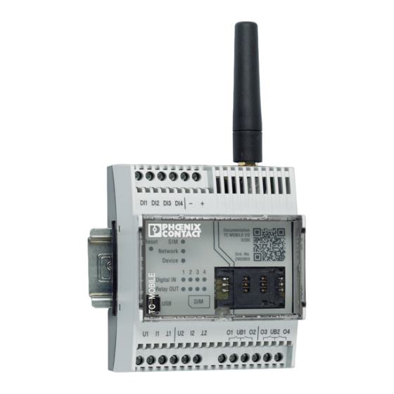
A USB connection to a computer with a web browser is all that is needed for configuration. Table 2-1 Product versions Designation Order Voltage range Communication TC MOBILE I/O X200 2903805 10 V ... 60 V DC – – E-mail TC MOBILE I/OX200 AC 2903806 93 V ... - Page 12 TC MOBILE I/O... 2.1.1 TC MOBILE I/O X200 and TC MOBILE I/O X300 0,5-0,6 Nm 5-7 lb In DI1 DI2 DI3 DI4 Documentation TC MOBILE I/O X200 Reset Network Ord.-No.: Device 2903806 1 2 3 4 Digital IN Relay OUT...
- Page 13 12 Relay 1 + 2 (N/O contact) 13 Relay 3 + 4 (N/O contact) 14 Lugs for closing the housing cover 15 Mini SIM card 16 SMA antenna connection (socket) 17 Extendable base latch for wall mounting 107812_en_00 PHOENIX CONTACT...
-
Page 14: Unpacking
The module is grounded by snapping it onto the DIN rail. • Place the device onto the DIN rail from above. • Push the front of the device toward the mounting surface until it audibly snaps into place. Figure 2-1 DIN rail mounting PHOENIX CONTACT 107812_en_00... - Page 15 Insert a washer between the extracted base latch and the level sub base. • Secure the device to the wall using the screws. – Maximum thread diameter 4 mm – Maximum head diameter 8.5 mm Figure 2-2 Wall mounting 107812_en_00 PHOENIX CONTACT...
-
Page 16: Connecting The Antenna
B I L t io B I L t io g i t g i t l a y l a y S I M S I M Figure 2-3 Inserting the SIM card PHOENIX CONTACT 107812_en_00... -
Page 17: Wiring
Use QUINT POWER power supplies from PhoenixContact directly on the device. Supply voltage to the device via terminals. 2.6.1 DC devices: TC MOBILE I/O X200 and TC MOBILE I/O X300 WARNING: Risk of electric shock During operation, certain parts of this device may carry hazardous voltages. Disregarding this warning may result in property damage and/or serious personal injury. - Page 18 TC MOBILE I/O... U1 I1 U2 I2 10 11 Figure 2-6 Analog inputs (DC devices) = Ground The analog inputs, can be switched between Current: I1 and 1 – Voltage: U1 and 1 or supply earth – PHOENIX CONTACT 107812_en_00...
- Page 19 No voltage above 230 V AC must occur at the device itself. Ensure that all signals and the supply voltage refer to the same neutral conductor. • Connect the device. Figure 2-7 Supply voltage: 93 V AC ... 250 V AC ND ND DI1 DI2 DI3 DI4 Figure 2-8 Digital inputs (AC devices) 107812_en_00 PHOENIX CONTACT...
- Page 20 TC MOBILE I/O... NOTE: Device damage Always connect the voltage source to the center contact of the relay (UB1, UB2) and the load to the N/O contact (O1, O2, O3, O4). Figure 2-9 Relay outputs (AC devices) PHOENIX CONTACT 107812_en_00...
-
Page 21: Removal
Push the locking pin downwards with a screwdriver and pull out the base latch. • Pull the device away from the DIN rail. Figure 2-10 Removal from the DIN rail 2.7.2 Wall • Remove screws. • Push the base latch inwards. Figure 2-11 Removal from the wall 107812_en_00 PHOENIX CONTACT... - Page 22 TC MOBILE I/O... PHOENIX CONTACT 107812_en_00...
-
Page 23: Configuration
“GPRS communication between two mobile network devices” on page 27 If you wish to use the receiving e-mail, alarm call or switching via call functions despite the increased security risk, please get in touch with Phoenix Contact. 107812_en_00 PHOENIX CONTACT... -
Page 24: Communication Channels Tc Mobile I/O X200
TC MOBILE I/O... Communication channels TC MOBILE I/O X200... 3.1.1 Sending e-mails The signaling systems can send alarms and cyclical messages by e-mail. For this purpose, GPRS communication is established with an e-mail server. The signaling systems can also send the entire log book as an e-mail. - Page 25 If the telephone number is authorized, the device closes, opens or changes one of more outputs, depending on the configuration. The device hangs up. Since the device does not respond to the telephone call, there are no costs. The user also receives a direct acknowledgment that the call has been received. 107812_en_00 PHOENIX CONTACT...
- Page 26 Communication via app Download the app free of You can also use the devices TC MOBILE I/O X200... via the app. The app sends the switch charge: commands. The app then receives the response from the device via an encrypted HTTPS data connection.
-
Page 27: Communication With An Odp Server With Tc Mobile I/O X300
The platform is configured in a top down concept. This means that the control center man- ages all central and important functions. The ODP server from Phoenix Contact enables open communication between the signaling system and the control center. -
Page 28: Configuration
: the device will be recognized as a virtual CD drive. If the autostart function is deactivated, start Setup.exe from the virtual CD drive. The driver for the device will be installed. ® • Linux and Mac OS : the driver is already integrated into the operating system. PHOENIX CONTACT 107812_en_00... - Page 29 The installation wizard will support you during initial startup of the device. No additional soft- ware is required. In order for the device to function, you must at least parameterize the points 1 ... 4 under “Configuration”. Figure 3-4 Installation wizard 107812_en_00 PHOENIX CONTACT...
- Page 30 In this way, your final customers can call up the diagnostics themselves, for example, but cannot change the parameterization of the device. Remote access via USB/Ethernet converter is not possible, because a virtual network card is automatically installed in the connected peer. USB/Ethernet converters do not usually support this function. PHOENIX CONTACT 107812_en_00...
- Page 31 SMS is sent by the device which is next in the signal chain. The time window within which the devices have to send confirmation can be set to between one minute and 999 hours. You are free to choose the text of the confirmation SMS. 107812_en_00 PHOENIX CONTACT...
- Page 32 The alarm can be triggered immediately or after a waiting period of 0 seconds to 999 hours. This means that switch bounce is avoided. You can save a different message text for each edge. Figure 3-7 Digital inputs PHOENIX CONTACT 107812_en_00...
- Page 33 999 hours. The device can send a confirmation SMS to the recipient after a relay is opened or closed. If the current fails or when the device is restarted, the relay is opened. 107812_en_00 PHOENIX CONTACT...
- Page 34 The SMS is sent to the selected device once. It is not possible to send an e-mail because the power consumption is too high. Status requests via SMS You can request the current status of the inputs and outputs via SMS. PHOENIX CONTACT 107812_en_00...
- Page 35 The contents of the log book are not saved in the event of power failure. Test Functions To check installation, you can execute the following actions using the web interface: – Switch outputs – Send test messages per e-mail – Send test messages per SMS 107812_en_00 PHOENIX CONTACT...
- Page 36 Firefox for the firmware update. 3.4.8 Downgrade Downgrading from firmware 2.x to an earlier version is not possible using web-based man- agement. The versions are not compatible. If a downgrade is urgently required, please con- tact Phoenix Contact directly. PHOENIX CONTACT 107812_en_00...
-
Page 37: Detecting And Removing Errors
• Select this virtual drive via “Start, Computer”. • Start Setup.exe from the virtual CD drive. The driver for the device will be installed. • Follow the instructions of the installation wizard. Figure 4-1 Virtual CD drive 107812_en_00 PHOENIX CONTACT... -
Page 38: Access Via The Web Browser Is Not Possible
Deactivate the proxy settings in your web browser (see „Internet Explorer 8“ or „Firefox 24.1 or later“). Advantage: The device can quickly be accessed. Disadvantage: During configuration, access to the Internet is not possible. After configuration, reset the proxy settings. Internet communication can then be used again. PHOENIX CONTACT 107812_en_00... - Page 39 Deactivate the proxy settings under “Tools, Internet Options, Connections, LAN Settings”. Figure 4-3 Proxy settings deactivated, Internet Explorer Firefox 24.1 or later Deactivate the proxy settings under “Tools, Options, Network, Settings”. Figure 4-4 Proxy settings deactivated, Firefox 107812_en_00 PHOENIX CONTACT...
- Page 40 If standard IP address 169.254.10.1 is already assigned on your computer, the device is au- tomatically assigned a different IP address. The installation wizard displays the new IP address during driver installation. Figure 4-7 IP address displayed during driver installation PHOENIX CONTACT 107812_en_00...
- Page 41 Sevenstax.dhcpsrv. Example: If IP address 169.254.10.2 is displayed here, then the address of the TC MOBILE device is 169.254.10.1. Figure 4-10 IP address 107812_en_00 PHOENIX CONTACT...
-
Page 42: The Content Is Not Correctly Displayed In The Web Browser
Internet Explorer 8.0 or later. This web browser cannot be used to update the firm- ware. 4.3.2 Possible case 2 (Internet Explorer only) The compatibility setting in Internet Explorer is incorrect. A script error message will be dis- played. Figure 4-11 Script error message PHOENIX CONTACT 107812_en_00... - Page 43 Display all websites in Compatibility View Figure 4-12 Deactivating the compatibility view, step 1 • Disable the “Compatibility View” checkbox under the “Extras” menu. Figure 4-13 Deactivating the compatibility view, step 2 • Reload the page. Restart the web browser, if required. 107812_en_00 PHOENIX CONTACT...
- Page 44 TC MOBILE I/O... PHOENIX CONTACT 107812_en_00...
-
Page 45: Technical Data
Accessories Operation of the wireless system is only permitted if accessories available from Phoenix Contact are used. The use of other accessory components could invalidate the operating license. For initial startup, you require a USB cable and an antenna. These accessories are not in- cluded in the scope of delivery. - Page 46 Software dongle for 150 remote control substations AX ODP SERVER 150FU 2700403 Software dongle for 200 remote control substations AX ODP SERVER 200FU 2700404 Software dongle for 250 remote control substations AX ODP SERVER 250FU 2700406 Other ODP license models on request PHOENIX CONTACT 107812_en_00...
-
Page 47: Comparison Of Product Features
For current input (configuration 4 mA ... 20 mA) as soon as current < 4 mA and ● ● per signal chain Send to individuals and groups of people (SMS and e-mail) ● ● Alarm to an ODP control system ● ● For ODP error, per SMS ● ● 107812_en_00 PHOENIX CONTACT... - Page 48 Change analog threshold values per SMS ● ● Reboot via SMS ● ● Manual or automatic updating of system time per SMS ● ● Time stamp from the ODP control system ● ● Switch calendar as backup for connection loss ● ● PHOENIX CONTACT 107812_en_00...
-
Page 49: Technical Data
70% ... 100% of the applied supply voltage Switching level “0” signal 0 V AC ... 50 V AC Switching level “1” signal 90 V AC ... 250 V AC Input current at 250 V AC 3.5 mA, typical 107812_en_00 PHOENIX CONTACT... - Page 50 (3 A / 120 V AC) 30,000 switch cycles (5 A / 250 V AC) Insulation distance between coil and contact 4000 V 3000 V Relay load curve - ohmic load X200, X300 X200 AC, X300 AC 70 100 PHOENIX CONTACT 107812_en_00...
- Page 51 SMS mode GPRS data link Relay not used 70°C 60°C Maximum relay load current: 1 A 60°C 55°C Maximum relay load current: 6 A (DC devices) 50°C 50°C Maximum relay load current: 5 A (AC devices) 50°C 50°C 107812_en_00 PHOENIX CONTACT...
-
Page 52: Conformance
For installations within the 3 m area and safety-related devices, there are additional requirements specified by EN 50121-4, table 1, note 1. This area is excluded from the manufacturer's declaration. Section 1, Paragraph 3 of EN 50121-4 shall apply. Use power supplies from the Phoenix Contact QUINT prod- uct range directly on the device. - Page 53 EN 61000-4-6 Frequency range 0.15 MHz ... 80 MHz Voltage 10 V Comment Criterion A Criterion A Normal operating behavior within the specified limits Criterion B Temporary adverse effects on the operating behavior, which the device corrects automatically 107812_en_00 PHOENIX CONTACT...
- Page 54 30%, number of periods 0.5 Test level 60%, number of periods 5 Comment Criterion B Criterion A Normal operating behavior within the specified limits Criterion B Temporary adverse effects on the operating behavior, which the device corrects automatically PHOENIX CONTACT 107812_en_00...
-
Page 55: Afcc Approval
A FCC approval 107812_en_00 PHOENIX CONTACT... - Page 56 TC MOBILE I/O... PHOENIX CONTACT 107812_en_00...
-
Page 57: Appendixes
IP address displayed during driver installation ........40 Figure 4-8: cmd.exe ....................41 Figure 4-9: DOS window ..................41 Figure 4-10: IP address ................... 41 Figure 4-11: Script error message ................42 Figure 4-12: Deactivating the compatibility view, step 1 .......... 43 107812_en_00 PHOENIX CONTACT... - Page 58 TC MOBILE I/O... Figure 4-13: Deactivating the compatibility view, step 2 .......... 43 PHOENIX CONTACT 107812_en_00...
-
Page 59: B 2 Index
Net data volume............36 Displays and operating elements NetBIOS name............30 AC device.............. 13 Noise emission ............52 DC device.............. 12 Noise immunity Downgrade ..............36 AC device.............. 54 Drivers................. 28 DC device.............. 53 FCC approval.............. 55 107812_en_00 PHOENIX CONTACT... - Page 60 DC device.............. 17 AC device.............. 20 DC device.............. 17 Removal Zone 2................9 DIN rail ..............21 Wall ............... 21 Reporting chain............31 Safety notes ..............7 Sending e-mails ............24 Sending SMS .............. 24 Serial number.............. 31 PHOENIX CONTACT 107812_en_00...
- Page 61 Index 107812_en_00 PHOENIX CONTACT...
- Page 62 TC MOBILE I/O... PHOENIX CONTACT 107812_en_00...
Need help?
Do you have a question about the TC MOBILE I/O X200 and is the answer not in the manual?
Questions and answers