Phoenix Contact Axioline F User Manual
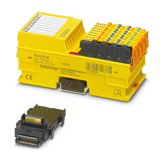
Power measurement module
Hide thumbs
Also See for Axioline F:
- User manual (148 pages) ,
- User manual (78 pages) ,
- User manual (110 pages)
Advertisement
Quick Links
Advertisement

Related Manuals for Phoenix Contact Axioline F


Summary of Contents for Phoenix Contact Axioline F
- Page 1 Axioline F, Power Measurement Module User manual...
- Page 2 UM EN AXL F PM EF 1F, revision 01 2020-12-02 This user manual is valid for: Designation Order No. AXL F PM EF 1F 2702671 PHOENIX CONTACT GmbH & Co. KG • Flachsmarktstraße 8 • 32825 Blomberg • Germany phoenixcontact.com...
- Page 3 Calculation of power values per phase ..........24 3.5.3 Sign of fundamental active and reactive power ........25 Data transmission via process data ..................26 Parameterizing the contents of IN process data ..........26 Input process data ....................27 3 / 42 PHOENIX CONTACT 108138_en_01...
- Page 4 Objects for identification (device rating plate) ........30 5.1.2 Miscellaneous standard objects ............31 Application objects, overview ................33 5.2.1 Objects for parameterization ..............33 5.2.2 Object for display ................. 35 5.2.3 Objects for control ................39 4 / 42 PHOENIX CONTACT 108138_en_01...
- Page 5 Safety notes Observe the safety instructions in the packing slip and the data sheet for the product. The documentation can be downloaded at phoenixcontact.net/products. 5 / 42 PHOENIX CONTACT 108138_en_01...
- Page 6 1.4.1 Intended use The module is designed for use within an Axioline F station. The power measurement module is used for direct measurement of AC currents up to 5 A, including neutral conductor current and phase conductor voltages up to 400 V AC (phase to neutral conductor) or outer conductor voltages up to 690 V AC (phase to phase).
- Page 7 Additional applicable documentation User manual, English: Axioline F: System and installation UM EN AXL F SYS INST User manual, English, Axioline F, diagnostic register, and error mes- UM EN AXL F SYS DIAG sages The documentation can be downloaded at phoenixcontact.net/products.
- Page 8 The following example shows the wiring for a four-wire three-phase mains with measurement of the neutral conductor current. Make sure that the potential of a connected neutral conductor is close to ground and does not exceed 45 V AC to ground. 8 / 42 PHOENIX CONTACT 108138_en_01...
- Page 9 Direct connection: Connection of a 3-phase load for power measurement in a star configuration with neutral conductor current Figure 2-2 Direct connection: Connection of a 3-phase load for power measurement in a delta configuration 9 / 42 PHOENIX CONTACT 108138_en_01...
- Page 10 With a configurable value of 1 ... 10000, the transmission ratio is 0.1 ... 1000.0. Example: If you set the value 1000 , the transmission ratio is 1 : 100.0. Figure 2-3 Connection of a 4-conductor network with current transformers 10 / 42 PHOENIX CONTACT 108138_en_01...
- Page 11 With a configurable value of 1 ... 10000, the transmission ratio is 0.1 ... 1000.0. Example: If you set the value 1000 , the transmission ratio is 1 : 100.0. Figure 2-4 Connection with current transformers and voltage transformers 11 / 42 PHOENIX CONTACT 108138_en_01...
- Page 12 Power P depending on cable length l in the secondary current range at 5 A = 1,5 mm l [m] Figure 2-6 Power P depending on cable length l in the secondary current range at 1 A 12 / 42 PHOENIX CONTACT 108138_en_01...
- Page 13 A phase angle error of 1° can distort the active power or fundamental reactive power by up to 1.7% of the apparent power, but the apparent power is not distorted. The module cannot correct this error. 13 / 42 PHOENIX CONTACT 108138_en_01...
- Page 14 When it comes to the accuracy and selection of voltage transformers, the same correction methods apply as for current transformers (see above). 14 / 42 PHOENIX CONTACT 108138_en_01...
- Page 15 (1.25 Hz) to reduce the DC components. The transient period for the filters is 59.9 ms for an accuracy of 1% and 88.4 ms for an ac- curacy of 0.1%. 15 / 42 PHOENIX CONTACT 108138_en_01...
- Page 16 , 01 : instantaneous values. Figure 3-2 Instantaneous value (scanning values) (not to scale) Scanning measured values are the instantaneous values of current and voltage according to phase, as well as neutral conductor current. 16 / 42 PHOENIX CONTACT 108138_en_01...
- Page 17 S0 pulses can be forwarded for energy recording outside the controller. The S0 pulses re- flect the total active power of all three phases. You can configure S0 pulse rates between 1 and 1,000 pulses/kWh via object 0E26 17 / 42 PHOENIX CONTACT 108138_en_01...
- Page 18 (hex) 4-conductor three-phase mains with uneven load (star or delta configuration) 4-conductor three-phase mains, economy circuit, open-Y (star configuration) From firmware version 1.10: 3-conductor three-phase mains (delta configura- tion) with uneven load 18 / 42 PHOENIX CONTACT 108138_en_01...
- Page 19 4-conductor three-phase mains with uneven load (star configuration): direct connection Figure 3-4 4-conductor three-phase mains with uneven load (star configuration): connection with current transformers Figure 3-5 4-conductor three-phase mains with uneven load (star configuration): connection with current and voltage transformers 19 / 42 PHOENIX CONTACT 108138_en_01...
- Page 20 The neutral conductor current is measured. Figure 3-7 4-conductor three-phase mains, economy circuit, open-Y (star configura- tion): connection with current and voltage transformers 20 / 42 PHOENIX CONTACT 108138_en_01...
- Page 21 3-conductor three-phase mains (delta configuration) with uneven load: di- rect connection Figure 3-9 3-conductor three-phase mains (delta configuration) with uneven load: connection with current transformers Figure 3-10 3-conductor three-phase mains (delta configuration) with uneven load: connection with current and voltage transformers 21 / 42 PHOENIX CONTACT 108138_en_01...
- Page 22 Power components per phase Key: Active power Fundamental active power Apparent power Fundamental apparent power Reactive power according to standard Fundamental reactive power Distortion reactive power Power factor λ Phase angle in relation to fundamental wave ϕ 22 / 42 PHOENIX CONTACT 108138_en_01...
- Page 23 ). However, the power factor only corresponds to cos( ) if there are no harmonics ϕ ϕ in the network. The cos( ) value represents the ratio of fundamental active power P to fundamental ap- ϕ parent power S 23 / 42 PHOENIX CONTACT 108138_en_01...
- Page 24 Calculation of the total power of the three-phase mains Only the following types of power exist in the three-phase mains: The fundamental reactive power and distortion reactive power are not defined for a three- phase mains. 24 / 42 PHOENIX CONTACT 108138_en_01...
- Page 25 The index “GW” has been omitted. The active power is calculated as follows: The reactive power is calculated as follows only in the absence of distortion: In contrast to the standard, the reactive power therefore has a sign. 25 / 42 PHOENIX CONTACT 108138_en_01...
- Page 26 After changing the connection method, reset the energy meter. For a complete overview of application objects, see Section 5, “Parameters, diagnostics and information”. You can parameterize the objects independently of one another. 26 / 42 PHOENIX CONTACT 108138_en_01...
- Page 27 Depending on object 0E13 : phase volt- : phase-to- phase voltage You obtain the actual reading by dividing the value in the IN process data by 1,000. This re- sults in three decimal places. 27 / 42 PHOENIX CONTACT 108138_en_01...
- Page 28 400.000 400.000 400.000 400.000 0006 1A80 400000 10.000 10.000 10.000 10.000 10.000 0000 2710 10000 0.001 0.001 0.001 0.001 0.001 0000 0001 0000 0000 -10.000 -10.000 -10.000 -10.000 -10.000 FFFF D8F0 -10000 28 / 42 PHOENIX CONTACT 108138_en_01...
- Page 29 PDI = parameters, diagnostics, and information Parameter and diagnostic data as well as other information is transmitted as objects via the PDI channel of the Axioline F station. For detailed information on PDI objects, please refer to the UM EN AXL F SYS INST user manual.
- Page 30 Standard objects 5.1.1 Objects for identification (device rating plate) Index (hex) Object name Rights Meaning Content Manufacturer 0001 VendorName Manufacturer name Phoenix Contact 0002 VendorID Manufacturer ID 00A045 0003 VendorText Manufacturer text Components and systems for industrial auto- mation 0012 VendorURL Manufacturer URL www.phoenixcontact.com...
- Page 31 003B PDIN_Descr IN process data description UM EN AXL F SYS INST 003C PDOUT_Descr OUT process data description UM EN AXL F SYS INST The objects 003B and 003C are only applicable to tools. 31 / 42 PHOENIX CONTACT 108138_en_01...
- Page 32 Overvoltage: one phase volt- 01 ... 03 8910 Overrange Green on Off age exceeds 400 V RMS Overcurrent: one current ex- 04 ... 07 8910 Overrange Green on Off ceeds 5 A 32 / 42 PHOENIX CONTACT 108138_en_01...
- Page 33 Representation in pro- UINT8 : power cess data: : energy power or energy Others not permitted 0E13 PM_TypeOfVoltage Representation in pro- UINT8 : phase voltage cess data: : phase-to-phase volt- voltage type Others not permitted 33 / 42 PHOENIX CONTACT 108138_en_01...
- Page 34 0.1 ... 1,000.0, default 1.0. 0E26 PM_S0PulseRate S0 pulse rate UINT16 Unit: pulses/kWh 1 ... 1000; 100 Resolution: 0.01 With a configurable value of 1 ... 1000, the transmission ratio is 0.01 ... 10.00, default 1.00. 34 / 42 PHOENIX CONTACT 108138_en_01...
- Page 35 Phase angle between Array, Unit: degrees current and voltage 3 * FLOAT32 .1: L1 .2: L2 .3: L3 0E39 PM_PowerFactor Power factor, cos Phi Array, 3 * FLOAT32 .1: L1 .2: L2 .3: L3 35 / 42 PHOENIX CONTACT 108138_en_01...
- Page 36 3 * FLOAT32 .1: I1/I2 .2: I2/I3 .3: I3/I1 0E45 PM_Basic_Values Basic values Record, See Section “Basic values 3 * INT32/ (Object 0E45 , PM_Ba- .1: L1 FLOAT32 sic_Values)” on page 39 .2: L2 .3: L3 36 / 42 PHOENIX CONTACT 108138_en_01...
- Page 37 Drawing No zero crossing Zero crossing No zero crossing (phase voltage < 5 V RMS) Overcurrent No overcurrent Overcurrent: (current > 5 A RMS) Overvoltage No overvoltage Overvoltage: (phase voltage > 400 V RMS) 37 / 42 PHOENIX CONTACT 108138_en_01...
- Page 38 Total object length: 32 bytes (4 elements each of 2 x 4 bytes) When writing to one of the objects 0E14 , 0E23 ,or 0E24 , the minimum and maxi- mum values will be deleted. 38 / 42 PHOENIX CONTACT 108138_en_01...
- Page 39 Meaning Data type Value Rights (hex) 0E50 PM_EnergyCountControl Power meter controller UINT8 : No action : Meter on : Meter off : Reset meter From firmware 1.10: : Reset meter and stop energy metering 39 / 42 PHOENIX CONTACT 108138_en_01...
- Page 40 AXL F PM EF 1F 40 / 42 PHOENIX CONTACT 108138_en_01...
- Page 41 The receipt of technical documentation (in particular user documentation) does not constitute any further duty on the part of Phoenix Contact to furnish information on modifications to products and/or technical documentation. You are responsible to verify the suitability and intended use of the products in your specific application, in particular with regard to observing the applicable standards and regulations.
- Page 42 Should you have any suggestions or recommendations for improvement of the contents and layout of our manuals, please send your comments to: tecdoc@phoenixcontact.com 42 / 42 PHOENIX CONTACT GmbH & Co. KG • Flachsmarktstraße 8 • 32825 Blomberg • Germany phoenixcontact.com...
- Page 44 PHOENIX CONTACT GmbH & Co. KG Flachsmarktstraße 8 32825 Blomberg, Germany Phone: +49 5235 3-00 Fax: +49 5235 3-41200 E-mail: info@phoenixcontact.com phoenixcontact.com...
Need help?
Do you have a question about the Axioline F and is the answer not in the manual?
Questions and answers