
Subscribe to Our Youtube Channel
Related Manuals for Phoenix Contact EMpro EEM-MA370


Summary of Contents for Phoenix Contact EMpro EEM-MA370
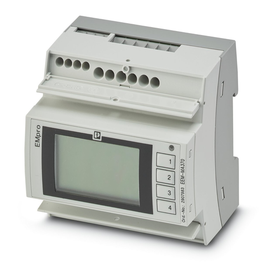
- Page 1 EMpro - multifunctional energy measuring devices for DIN rail mounting User manual...
-
Page 2: Eem-Mb-370-Pn
This user manual is valid for: Designation Order No. EEM-MA370 2907983 EEM-MA371 2908307 EEM-MA370-R 2907980 EEM-MA371-R 2907985 EEM-MB370 2907954 EEM-MB371 2907955 EEM-MB370-PN 2907984 EEM-MB371-PN 2908308 EEM-MB370-EIP 2907971 EEM-MB371-EIP 2907976 PHOENIX CONTACT GmbH & Co. KG • Flachsmarktstraße 8 • 32825 Blomberg • Germany phoenixcontact.com... -
Page 3: Table Of Contents
Step 4: Grid type ..................33 5.1.5 Step 5a: Current input (energy measuring device with current transformer) ..................34 5.1.6 Step 5b: Current input (energy measuring device with Rogows- ki coil) ....................35 5.1.7 Step 6: Voltage input ................35 3 / 196 109357_en_00 PHOENIX CONTACT... - Page 4 Access and passwords..................72 8.1.1 Editing access data via the display ............72 8.1.2 Editing access data via the web server ..........73 8.1.3 Deactivating the configuration via the display ........74 8.1.4 Deactivating the Modbus communication interface ......75 4 / 196 PHOENIX CONTACT 109357_en_00...
- Page 5 Firmware update....................131 10.6.1 Execution ...................131 10.6.2 Security ....................133 11 Communication ........................135 11.1 Ethernet ......................138 11.1.1 IP addressing ..................138 11.1.2 Configuration of the communication interface ........139 11.1.3 Status of the communication interface ..........140 11.1.4 Security ....................140 5 / 196 109357_en_00 PHOENIX CONTACT...
- Page 6 11.7 Register table ....................172 11.8 Contents of the register table................172 11.9 Description of the register table .................172 12 Technical data ........................177 Appendix for document lists....................181 List of figures .....................181 List of tables ......................187 Index........................189 6 / 196 PHOENIX CONTACT 109357_en_00...
-
Page 7: For Your Safety
– Qualified application programmers and software engineers. The users must be familiar with the relevant safety concepts of automation technology as well as applicable stan- dards and other regulations. 7 / 196 109357_en_00 PHOENIX CONTACT... -
Page 8: Field Of Application Of The Product
Modifications to hardware and firmware of the device are not permitted.Incorrect operation or modifications to the device can endanger your safety or damage the device. Do not repair the device yourself. If the device is defective, please contact Phoenix Contact. Safety notes WARNING: Risk of death due to electric shock Only use external current transformers with reinforced or double isolation. -
Page 9: Device Description
Numerous parameters that are important for operating an electrical system are determined by means of the voltages and currents measured by the EMpro energy measuring devices. Apparent power, active power and reactive power are measured in all four quadrants (consumption, supply). 9 / 196 109357_en_00 PHOENIX CONTACT... -
Page 10: Grid Type
– Network (TCP/IP) – Interfaces with higher-level control systems – Digital output (with logic functions) – Digital input – Pulse counter – Date/time (realtime clock, SNTP compatible) – Identifier (of metering point) – Display 10 / 196 PHOENIX CONTACT 109357_en_00... - Page 11 A variety of hardware and software interfaces can be used to communicate with higher-level control systems. At the time of writing this document, the following interfaces are available: – Modbus/RTU (RS-485) – Modbus/TCP (Ethernet) – PROFINET (Ethernet, Dual Port) – EtherNet/IP (Ethernet, Dual Port) 11 / 196 109357_en_00 PHOENIX CONTACT...
- Page 12 – Device control – Device status – Measuring system control – Process data – Measured values – Counter values – Pulse counter – Statistics – Total harmonic distortion THD – Harmonics – Voltage quality 12 / 196 PHOENIX CONTACT 109357_en_00...
-
Page 13: Product Overview
Modbus/TCP without display EEM-MB370 EEM-MB371 2907954 2907955 Modbus/TCP with display + EEM-MA370-R EEM-MA371-R Modbus/RTU 2907980 2907985 Modbus/TCP without display + EEM-MB370-PN EEM-MB371-PN PROFINET 2907984 2908308 Modbus/TCP without display + EEM-MB370-EIP EEM-MB371-EIP EtherNet/IP™ 2907971 2907976 13 / 196 109357_en_00 PHOENIX CONTACT... - Page 14 EMpro - multifunctional energy measuring devices for DIN rail mounting 14 / 196 PHOENIX CONTACT 109357_en_00...
-
Page 15: Mounting And Installation
You can snap the device onto a DIN rail in the control cabinet. The mounting position can be freely selected, but will be determined by the readability of the LCD. Figure 3-1 Mounting Figure 3-2 Removal 15 / 196 109357_en_00 PHOENIX CONTACT... -
Page 16: Installation
When the current transformer is operated with an open secondary circuit, hazardous voltages may occur at the secondary terminal blocks. When measuring by means of current transformers or Rogowski coils, the accuracy is greatly influenced by the quality of the current sensors used. 16 / 196 PHOENIX CONTACT 109357_en_00... -
Page 17: Pin Assignment
V1, V2, V3, VN Voltage measuring input FE Functional ground RJ45 Ethernet connection (Modbus) Status Optional (depending on the version): 1 x RS-485 RS-485 connection (Modbus/RTU) 2x ETH RJ45 Ethernet connection (PROFINET) Ethernet connection (EtherNet/IP™) 17 / 196 109357_en_00 PHOENIX CONTACT... - Page 18 V1, V2, V3, VN Voltage measuring input FE Functional ground RJ45 Ethernet connection (Modbus) Status Optional (depending on the version): 1 x RS-485 RS-485 connection (Modbus/RTU) 2x ETH RJ45 Ethernet connection (PROFINET) Ethernet connection (EtherNet/IP™) 18 / 196 PHOENIX CONTACT 109357_en_00...
-
Page 19: Supply
Connection L/N Connection L/L L1´ L2´ L3´ N´ PE´ Figure 3-6 Connection L/L Supply voltage range: 100 V AC ... 230 V AC ±20% 150 V DC ... 250 V DC ±20% 16 A Fuse: 19 / 196 109357_en_00 PHOENIX CONTACT... -
Page 20: Grid Types
V1 V2 V3 VN L1´ L2´ L3´ N´ PE´ Figure 3-7 One-phase network, two conductors, one current transformer 2PH-2W-1CT V1 V2 V3 VN L1´ L2´ L3´ N´ PE´ Figure 3-8 Two-phase network, two conductors, one current transformer 20 / 196 PHOENIX CONTACT 109357_en_00... -
Page 21: Three-Phase Network, Three Conductors, One Current Transform
V1 V2 V3 VN L1´ L2´ L3´ N´ PE´ Figure 3-11 Three-phase network, three conductors, three current transformers 3PH-4W-1CT V1 V2 V3 VN L1´ L2´ L3´ N´ PE´ Figure 3-12 Three-phase network, four conductors, one current transformer 21 / 196 109357_en_00 PHOENIX CONTACT... -
Page 22: Three-Phase Network, Four Conductors, Three Current Transform
V1 V2 V3 VN L1´ L2´ L3´ N´ PE´ Figure 3-13 Three-phase network, four conductors, three current transformers 2PH-3W-2CT V1 V2 V3 VN L1´ L2´ L3´ N´ PE´ Figure 3-14 Two-phase network, three conductors, two current transformers 22 / 196 PHOENIX CONTACT 109357_en_00... -
Page 23: One-Phase Network, Two Conductors, One Rogowski Coil
V1 V2 V3 VN L1´ L2´ L3´ N´ PE´ Figure 3-16 Two-phase network, two conductors, one Rogowski coil 3PH-3W-1RC V1 V2 V3 VN L1´ L2´ L3´ N´ PE´ Figure 3-17 Three-phase network, three conductors, one Rogowski coil 23 / 196 109357_en_00 PHOENIX CONTACT... -
Page 24: Three-Phase Network, Three Conductors, Three Rogowski Coils
V1 V2 V3 VN L1´ L2´ L3´ N´ PE´ Figure 3-20 Three-phase network, four conductors, three Rogowski coils 2PH-3W-2RC V1 V2 V3 VN L1´ L2´ L3´ N´ PE´ Figure 3-21 Two-phase network, three conductors, two Rogowski coils 24 / 196 PHOENIX CONTACT 109357_en_00... -
Page 25: Operating And Indication Elements
LCD display, two-color backlit Operating buttons 1...4 for displaying measured values and for changing the configuration Pulse LED Energy measuring device without display Impuls Status Reset Figure 4-1 EEM-MB-370 Reset button Status LED Pulse LED 25 / 196 109357_en_00 PHOENIX CONTACT... -
Page 26: Energy Measuring Device Without Display, With Additional Profinet Interface
Table 4-1 Name Color/status Description of PROFINET communication PROFINET communication Communication OK On (red) Fault in the communication controller or no physi- cal connection to the PROFINET network Flashing PROFINET timeout Green Flashing DCP flashing 26 / 196 PHOENIX CONTACT 109357_en_00... -
Page 27: Energy Measuring Device Without Display, With Additional Ethernet/Ip Interface
Device is not configured On (green) No error Flashing (red) Repairable error/peripheral error/message, e.g., overload, output driver, IFS device er- ror, configuration error On (red) Internal error Replace the device. Flashing (green/red) Self test 27 / 196 109357_en_00 PHOENIX CONTACT... -
Page 28: Technical Data Of The Display
Technical data of the display Technical data Display technology FSTN positive, transflective Resolution of devices for installation on 128 x 80 front panel Viewing angle Min. 30° (horizontal and vertical) Backlight White and red 28 / 196 PHOENIX CONTACT 109357_en_00... -
Page 29: Displaying The Events
Table 4-3 Displaying the events Icon Meaning Voltage transducer configured Measured values faulty (flashing) Tariff 1 set Tariff 2 set Tariff 3 set Tariff 4 set Network connected Warning User logged in User logged out 29 / 196 109357_en_00 PHOENIX CONTACT... -
Page 30: Operating Elements On The Display (Softkeys)
Scroll down Select menu page Exit menu page Edit setting Apply modified setting Increment (increase) Decrement (decrease) Next position Confirm query Reject query/first configuration: go back to start Reset: the displayed values are reset 30 / 196 PHOENIX CONTACT 109357_en_00... -
Page 31: Basic Device Configuration
To start the first configuration (basic device configuration) of your energy measuring device, press the button. Figure 5-1 Starting the basic device configuration 5.1.1 Step 1: Language selection Figure 5-2 Language selection Use the buttons to select the desired language. To proceed, press the button. 31 / 196 109357_en_00 PHOENIX CONTACT... -
Page 32: Step 2: Network Settings
To open edit mode, press the button. To scroll through the possible values, use the buttons Next, apply the settings by pressing the button. After you have entered all settings, press the button. 32 / 196 PHOENIX CONTACT 109357_en_00... -
Page 33: Step 4: Grid Type
Selection of grid type with Rogowski coils Use the buttons to select the desired grid type. To proceed, press the button. Explanations and information on the various grid types are available in Section “Grid types” on page 33 / 196 109357_en_00 PHOENIX CONTACT... -
Page 34: Step 5A: Current Input (Energy Measuring Device With Current Transformer)
To set the secondary current, proceed in the same way as for setting the primary current. To invert the current inputs, activate the checkbox below the appropriate current input with the button. To continue the basic device configuration, press the button. 34 / 196 PHOENIX CONTACT 109357_en_00... -
Page 35: Step 5B: Current Input (Energy Measuring Device With Rogowski Coil)
If no voltage transducer is used, enter the nominal voltage by means of the buttons. Select it with the button. Use the buttons to make changes. To save the changes, press the button. To proceed, press the button. 35 / 196 109357_en_00 PHOENIX CONTACT... -
Page 36: Step 7: Configuration Overview
PIN. To apply the changes, press the button. To finish the basic device configuration, press the button. To ensure safe operation, we recommend changing the access data for the display! 36 / 196 PHOENIX CONTACT 109357_en_00... -
Page 37: Basic Device Configuration Via The Web Server
To start the basic device configuration via the web server, open the Internet browser. Enter the following URL: IP address: 192.168.1.2 Subnet mask: 255.255.255.0 Default gateway: 0.0.0.0 DHCP: DNS server: 0.0.0.0 Make sure that your computer and the energy measuring device are in the same network. 37 / 196 109357_en_00 PHOENIX CONTACT... -
Page 38: Step 1: Network Settings
Navigation on the web “Network settings” server Figure 5-13 Network settings Status Here, an overview of the current network configuration is displayed. Settings Enter the desired network settings as appropriate for the respective application. 38 / 196 PHOENIX CONTACT 109357_en_00... -
Page 39: Step 2: Selecting The Grid Type
The second step is the selection of the grid type for the application. Figure 5-14 Grid type Taking the device installation into account, select the desired grid type from the options provided in the overview. 39 / 196 109357_en_00 PHOENIX CONTACT... -
Page 40: Step 3: Configuration Of The Current Input (Current Transformer)
Select the secondary current (1 A or 5 A) of the current transformer. Inversion With this function, the respective phase of the current transformer is inverted by the firmware. It is no longer necessary to rewire the two conductors. 40 / 196 PHOENIX CONTACT 109357_en_00... -
Page 41: Step 3: Configuration Of The Current Input (Rogowski Coil)
Configuring the current input is the third step of the basic device configuration. Figure 5-16 Current input (Rogowski coil) Primary Enter the primary current of the application here. Preselection Select a Rogowski coil of Phoenix Contact. You do not have to configure any other settings. 41 / 196 109357_en_00 PHOENIX CONTACT... - Page 42 With this function, the respective phase of the Rogowski coil is inverted by the firmware. It is no longer necessary to rewire the two conductors. If you use Rogowski coils of manufacturers other than Phoenix Contact, you have to configure additional settings.
-
Page 43: Step 4: Voltage Input
Basic device configuration 5.2.5 Step 4: Voltage input If you use a voltage transducer in your application, activate the checkbox here. Subsequently follow the next steps. Figure 5-17 Voltage input 43 / 196 109357_en_00 PHOENIX CONTACT... -
Page 44: Optional: Voltage Transducer
EMpro - multifunctional energy measuring devices for DIN rail mounting 5.2.6 Optional: Voltage transducer Figure 5-18 Voltage input with voltage transducer Primary Enter the primary voltage of the voltage transducer. Secondary Enter the secondary voltage of the voltage transducer. 44 / 196 PHOENIX CONTACT 109357_en_00... -
Page 45: Step 5: Configuration Overview
Basic device configuration 5.2.7 Step 5: Configuration overview Figure 5-19 Configuration overview 45 / 196 109357_en_00 PHOENIX CONTACT... - Page 46 EMpro - multifunctional energy measuring devices for DIN rail mounting Check all settings and close the basic device configuration. For your own safety, we recommend changing the access data for the web server! 46 / 196 PHOENIX CONTACT 109357_en_00...
-
Page 47: Navigation Structure And Display
Navigation structure and display Navigation structure and display Menu structure on the display Figure 6-1 Menu structure on the display 47 / 196 109357_en_00 PHOENIX CONTACT... -
Page 48: Menu Structure On The Web Server
EMpro - multifunctional energy measuring devices for DIN rail mounting Menu structure on the web server Figure 6-2 Menu structure on the web server 48 / 196 PHOENIX CONTACT 109357_en_00... - Page 49 A defined measuring point, which you can name as desired – Language selection The menu tree contains the following: Home: Reading measured data and measurement values Settings: Configuring the device and device parameters System: Managing rights and provision of information and data 49 / 196 109357_en_00 PHOENIX CONTACT...
- Page 50 EMpro - multifunctional energy measuring devices for DIN rail mounting 50 / 196 PHOENIX CONTACT 109357_en_00...
-
Page 51: Device Settings And Information
Navigation on the display “Language” Figure 7-1 “Language” menu Figure 7-2 Language selection You can select the display language via the display. The default setting for the language is English. 51 / 196 109357_en_00 PHOENIX CONTACT... -
Page 52: Date And Time
The date and time settings can only be changed via the integrated web server or the Mod- bus communication interface. The web server provides the following modes for setting the date and time: – Manual – SNTP server 52 / 196 PHOENIX CONTACT 109357_en_00... -
Page 53: Setting The Date And Time Manually
Here, you can select a time zone. You can find a list of all time zones in Section “Time zones” on page Summer time rule Here, you can select a summer time rule. A description of the summer time rules can be found in Section “Summer time rule” on page 53 / 196 109357_en_00 PHOENIX CONTACT... -
Page 54: Synchronizing The Date And Time With An Sntp Server
Here, you can select a time zone. You can find a list of all time zones in Section “Time zones” on page Summer time rule Here, you can select a summer time rule. A description of the summer time rules can be found in Section “Summer time rule” on page 54 / 196 PHOENIX CONTACT 109357_en_00... -
Page 55: Time Zones
Asia (Dushanbe, Tashkent) India (Maldives) GMT +05:30 Asia (Calcutta, Colombo) GMT +05:45 Asia (Kathmandu) GMT +06:00 Asia (Almaty, Bishkek, Dacca, Yekaterinburg, Thimbu) GMT +06:30 Asia (Rangoon), India (Cocos) GMT +07:00 Asia (Bangkok, Jakarta, Novosibirsk, Omsk) 55 / 196 109357_en_00 PHOENIX CONTACT... - Page 56 Australia (Brisbane, Melbourne, Queensland, Sydney, Tasmania) GMT +11:00 Asia (Vladivostok) Pacific (Guadalcanal) GMT +11:30 Pacific (Norfolk) GMT +12:00 Asia (Kamchatka) Pacific (Auckland, Fiji, Majuro) GMT +12:45 Pacific (Chatham) GMT +13:00 Pacific (Apia, Enderbury, Tongatapu) GMT +14:00 Pacific (Kiritimati) 56 / 196 PHOENIX CONTACT 109357_en_00...
-
Page 57: Summer Time Rule
You can select the summer time rule for Europe or the USA, or set a summer time rule man- ually. If you set the summer time rule manually, you can specify the start and end of the sum- mer time rule: – Month – Day of week – Hours – Minutes 57 / 196 109357_en_00 PHOENIX CONTACT... -
Page 58: Adjusting The Display (Contract, Brightness, Illumination Time Of Backlight)
Adjusting the contrast of the display Navigation on the display “Display, Contrast” Contrast Figure 7-8 Menu: “Display, Contrast” Figure 7-9 Settings: “Display, Contrast” You can set the contrast of the display. The default setting for the contrast is 50%. 58 / 196 PHOENIX CONTACT 109357_en_00... -
Page 59: Adjusting The Brightness Of The Display
Navigation on the display “Display, Brightness“ Figure 7-10 Menu: “Display, Brightness“ Figure 7-11 Settings: “Display, Brightness“ You can adjust the brightness of the display. The default setting for the brightness of the dis- play is 100%. 59 / 196 109357_en_00 PHOENIX CONTACT... -
Page 60: Adjusting The Illumination Time Of The Backlight
EMpro - multifunctional energy measuring devices for DIN rail mounting 7.3.3 Adjusting the illumination time of the backlight Navigation on the display “Display, Permanent light, Illumination time” Figure 7-12 Menu: “Display, Permanent light” Figure 7-13 Settings: “Display, Permanent light” 60 / 196 PHOENIX CONTACT 109357_en_00... -
Page 61: Figure 7-14: Settings: "Illumination Time
When the “Permanent light” checkbox is disabled, you can freely define the duration for which the backlight remains lit. The default setting for the illumination time is 20 seconds. You can also change the settings for the illumination time via the web server. 61 / 196 109357_en_00 PHOENIX CONTACT... -
Page 62: Selecting The Format Of The Standard Display (Iec Or Ieee)
The default setting is IEC. You can also change the format for the standard displays via the web server (see Section “Adjusting the display via the web server” on page 65). 62 / 196 PHOENIX CONTACT 109357_en_00... -
Page 63: Activating Color Change For Alarm
In the default setting, the color change is enabled. You can also change the settings for the alarm light via the web server (see “Red color change in case of error” on page 65). 63 / 196 109357_en_00 PHOENIX CONTACT... -
Page 64: Selecting The Refresh Time For Displaying Measured Values
Figure 7-20 Settings: “Display, Refresh time” Refresh rate You can choose between three refresh times for displaying the measured values: – 500 ms – – The default setting for the refresh time is 1 s. 64 / 196 PHOENIX CONTACT 109357_en_00... -
Page 65: Adjusting The Display Via The Web Server
If this checkbox is enabled, the color change in the event of an error is active. If this check- of error box is disabled, the color change in the event of an error is inactive. In the default setting, this checkbox is enabled. 65 / 196 109357_en_00 PHOENIX CONTACT... -
Page 66: Device Information
The following device information can be read on the display: – Hardware version – Firmware version – Device label – Article number – UUID – Date and time of production – Serial number – Bootloader revision 66 / 196 PHOENIX CONTACT 109357_en_00... -
Page 67: Resetting The Device To Default Settings
Figure 7-25 Menu: “System, Factory reset” With the device PIN, the device can be reset to the default settings. In the process, all configurations are lost and the device is returned to the delivery state. 67 / 196 109357_en_00 PHOENIX CONTACT... - Page 68 EMpro - multifunctional energy measuring devices for DIN rail mounting 68 / 196 PHOENIX CONTACT 109357_en_00...
-
Page 69: Figure 0-1: Settings: "Illumination Time
Device settings and information 69 / 196 109357_en_00 PHOENIX CONTACT... - Page 70 EMpro - multifunctional energy measuring devices for DIN rail mounting 70 / 196 PHOENIX CONTACT 109357_en_00...
-
Page 71: Configuration
Configuration via Modbus In addition to the web server, the Modbus communication interface can also be used for de- vice configuration. 71 / 196 109357_en_00 PHOENIX CONTACT... -
Page 72: Access And Passwords
Under “PIN”, change the preset PIN for access permission. Subsequently apply it by confirming the change. In addition to the option to change the PIN, the device also offers an option for deactivating the PIN. 72 / 196 PHOENIX CONTACT 109357_en_00... -
Page 73: Editing Access Data Via The Web Server
Figure 8-3 Menu: “System, User management, Change password” The default setting for the password is “adm1n”. Under “Change password”, change the preset password for access permission. Confirm the change by clicking the “Change password” button. 73 / 196 109357_en_00 PHOENIX CONTACT... -
Page 74: Deactivating The Configuration Via The Display
You can continue to use the control buttons of the device to read measurement values. If the “Activate configuration via display” checkbox is disabled, it is not possible to use the function for deactivating the web server. The display and web server cannot be deactivated simultaneously. 74 / 196 PHOENIX CONTACT 109357_en_00... -
Page 75: Deactivating The Modbus Communication Interface
Figure 8-7 Setting: “System, PIN active” If you disable the “WBM active” checkbox, the device no longer allows access via the communication interface. Through this deactivation, access to the web server is also prohibited. 75 / 196 109357_en_00 PHOENIX CONTACT... - Page 76 EMpro - multifunctional energy measuring devices for DIN rail mounting This precludes use of the function for deactivating the control buttons. The display and web server cannot be deactivated simultaneously. 76 / 196 PHOENIX CONTACT 109357_en_00...
-
Page 77: Transferring Configuration Data
Navigation on the web “System, Configuration data, Export configuration” server Figure 8-8 Menu: “System, Configuration data, Export configuration” If you want to export the entire device configuration, all checkboxes except the network configuration are enabled. 77 / 196 109357_en_00 PHOENIX CONTACT... -
Page 78: Importing Configuration Data
If you want to load an existing configuration file onto the device, you can use the “Choose file” button to select it. Use the “Import” button to load the selected file onto the device. 78 / 196 PHOENIX CONTACT 109357_en_00... -
Page 79: Direct Transfer Of Configuration Data
Direct transfer of configuration data Navigation on the web “System, Configuration data, Transfer configuration” server Figure 8-10 Menu: “System, Configuration data, Transfer configuration” By directly transferring the configuration data, you prevent caching on a local computer. 79 / 196 109357_en_00 PHOENIX CONTACT... - Page 80 Enter the device addresses and passwords into the respective fields. To check the connection to the entered device, click the “Check connection” button. Click the “Transfer” button to transfer the selected configuration data to the devices. 80 / 196 PHOENIX CONTACT 109357_en_00...
-
Page 81: Measuring Technology
Meter readings Navigation on the web “Home, Meter readings” server Figure 9-1 Menu: “Home, Meter readings” The device provides various meter readings for measuring the energy data. These are described in the following sections. 81 / 196 109357_en_00 PHOENIX CONTACT... -
Page 82: Energy Meters
This energy meter is always counting. This energy meter cannot be reset. The following energy data is recorded: – Active energy: supply (Ea+), consumption (Ea-) – Reactive energy: supply (Er+), consumption (Er-) – Apparent energy (Es) 82 / 196 PHOENIX CONTACT 109357_en_00... -
Page 83: Energy Resettable
The reset can be performed by means of the web server, the control buttons on the display, or the Modbus communication interface. The following energy data is recorded: – Active energy: supply (Ea+), consumption (Ea-) – Reactive energy: supply (Er+), consumption (Er-) – Apparent energy (Es) 83 / 196 109357_en_00 PHOENIX CONTACT... -
Page 84: Tariff Meter
The reset can be performed by means of the web server, the control buttons on the display, or the Modbus communication interface. The following energy data is recorded for each tariff meter: – Active energy: supply (Ea+), consumption (Ea-) – Reactive energy: supply (Er+), consumption (Er-) – Apparent energy (Es) 84 / 196 PHOENIX CONTACT 109357_en_00... -
Page 85: Operating Hours Counter
This counter is a load counter that starts running from a configurable power threshold (in W). The default setting for the power threshold is 100 W. The value can be configured via the Modbus communication interface. 85 / 196 109357_en_00 PHOENIX CONTACT... -
Page 86: Statistics
Power – Predictions For each average value, the minimum and maximum averages are always recorded and displayed. The data can be called up via the web server, the display and via the communication interface. 86 / 196 PHOENIX CONTACT 109357_en_00... -
Page 87: Figure 9-10: Menu: "Settings, Average Values
Navigation on the web “Settings, Average values” server Figure 9-10 Menu: “Settings, Average values” Status Here, the current status of the average value generation is shown. 87 / 196 109357_en_00 PHOENIX CONTACT... -
Page 88: Figure 9-11 Menu: "Average Values, Settings
EMpro - multifunctional energy measuring devices for DIN rail mounting Figure 9-11 Menu: “Average values, Settings” Settings Here, enter the configuration in hh:mm:ss for the average value generation. The average values can be synchronized via the digital input by enabling the checkbox. 88 / 196 PHOENIX CONTACT 109357_en_00... -
Page 89: Figure 9-12 Avg Over Fixed Interval (Fixed Block)
The intervals slide and have a set measuring interval length. The average value is measuring interval length generated and updated with the sliding speed. During each update, the average is generated for the last completed interval. Figure 9-13 Sliding average value (sliding block) 89 / 196 109357_en_00 PHOENIX CONTACT... -
Page 90: Figure 9-14 Rolling Average Value (Rolling Block)
Example: If the selected interval is 15 minutes, three 5-minute subintervals have to be selected to match it. The average value is generated and updated at the end of each completed subinterval. Figure 9-14 Rolling average value (rolling block) 90 / 196 PHOENIX CONTACT 109357_en_00... -
Page 91: Figure 9-15: Prediction Calculation (Equally Weighted Average)
As each new value is recorded, the weight of the individual values decreases (exponentially). Figure 9-16 Prediction generation (weighted average) 91 / 196 109357_en_00 PHOENIX CONTACT... - Page 92 EMpro - multifunctional energy measuring devices for DIN rail mounting 92 / 196 PHOENIX CONTACT 109357_en_00...
-
Page 93: 10 Functions
10 Functions 10.1 Digital input The digital input complies with IEC 61131-2 Type 3. It includes the following functions: – Impulse counter – Tariff selection – Synchronization of average values – Acknowledgment of alarms 93 / 196 109357_en_00 PHOENIX CONTACT... -
Page 94: Figure 10-1 Digital Input
By clicking the respective link, you can access the configuration page for the function. Settings An identifier can be assigned to the digital input. With the checkbox, it can be activated or deactivated. In the default settings, the digital input is activated. 94 / 196 PHOENIX CONTACT 109357_en_00... -
Page 95: Impulse Counter
The impulse corresponds to the set value and is thus an additional multiplier. The valid value range is 1 … 65535. Unit Select a unit from the drop-down menu, or assign an own unit by selecting “Custom”. 95 / 196 109357_en_00 PHOENIX CONTACT... - Page 96 Unit: You can select between the following units: – – kVAh – kvarh – – – m³ – – – – – – Custom You can use the “Custom” option to define an own unit. 96 / 196 PHOENIX CONTACT 109357_en_00...
-
Page 97: Tariff Selection
Via the web server, you can manually configure up to four tariffs (identifiers 1 to 4) and read them via the communication interface. Navigation on the web “Settings, Tariffs” server Figure 10-3 Menu: “Settings, Tariffs, Digital input” 97 / 196 109357_en_00 PHOENIX CONTACT... - Page 98 Define the two identifiers (names) for your tariffs. Mode Specify the digital input as method for using the tariff selection. Digital input Define the status of the digital input in relation to the identifier. 98 / 196 PHOENIX CONTACT 109357_en_00...
-
Page 99: Synchronization Of Average Values
“UL-L, UL-L ...” Figure 10-4 Menu: “UL-L” Figure 10-5 Menu: “UL-L, UL-L instantaneous“ (instantaneous values, instantaneous) Figure 10-6 Menu: “UL-L, UL-L Min“ (min. values, min) Figure 10-7 Menu: “UL-L, UL-L Max“ (max. values, max) 99 / 196 109357_en_00 PHOENIX CONTACT... -
Page 100: Figure 10-8 Menu: "Ul-L, Ul-L Avg Min" (Minimum Average Values, Avg Min)
EMpro - multifunctional energy measuring devices for DIN rail mounting Figure 10-8 Menu: “UL-L, UL-L AVG Min“ (minimum average values, AVG min) Figure 10-9 Menu: “UL-L, UL-L AVG“ (average values, AVG) Figure 10-10 Menu: “UL-L, UL-L AVG max“ (max. average values, AVG max) 100 / 196 PHOENIX CONTACT 109357_en_00... -
Page 101: Acknowledgment Of Alarms
After the error status has been restored to the normal status (operation) of the applications, the alarm message disappears again. You can save an error status in the application until it is manually reset via the digital input. 101 / 196 109357_en_00 PHOENIX CONTACT... -
Page 102: Digital Output
Figure 10-12 Menu: “Settings, Digital output” Status The “Status” area shows the current status of the digital output. Identifier The identifier can be used to assign a user-specific designation to the digital output. 102 / 196 PHOENIX CONTACT 109357_en_00... - Page 103 The default setting for the digital output is NC (normally closed). Only one function can be configured at a time. – Impulse – Device status – Manual – Alarm – Rotary field direction – Deactivated The digital output is deactivated by default. 103 / 196 109357_en_00 PHOENIX CONTACT...
-
Page 104: Impulse
EMpro - multifunctional energy measuring devices for DIN rail mounting 10.2.1 Impulse Navigation on the web “Settings, Digital output”, “Impulse” function server Figure 10-13 Menu: “Settings, Digital output”, “Impulse” function 104 / 196 PHOENIX CONTACT 109357_en_00... - Page 105 Other configuration parameters are: Valency The impulse corresponds to the set value. The valid value range is 0.01 … 655.35 in kWh. Impulse duration The valid value range is 30 … 900 in ms. 105 / 196 109357_en_00 PHOENIX CONTACT...
-
Page 106: Device State
Here, it is also possible to define whether the output is normally closed (NC) or normally open (NO) in idle state. Navigation on the web “Settings, Digital output”, “Device state” function server Figure 10-14 Menu: “Settings, Digital output”, “Device state” function 106 / 196 PHOENIX CONTACT 109357_en_00... - Page 107 The identifier can be used to assign a user-specific designation to the digital output. Idle level There are two possible statuses for the idle level. – NC: Normally closed – NO: Normally open The default setting for the digital output is NO. 107 / 196 109357_en_00 PHOENIX CONTACT...
-
Page 108: Manually
The “Status” area shows the current status of the digital output. Identifier The identifier can be used to assign a user-specific designation to the digital output. Idle level There are two possible statuses for the idle level. 108 / 196 PHOENIX CONTACT 109357_en_00... -
Page 109: Alarm
The “Alarm” function can be used to react to changes to the measurement values. You can define upper and lower thresholds for the domain. If the measured values are outside of these thresholds, the alarm function is activated and sent via the digital output. 109 / 196 109357_en_00 PHOENIX CONTACT... -
Page 110: Figure 10-16 Menu: "Settings, Digital Output", "Alarm" Function
EMpro - multifunctional energy measuring devices for DIN rail mounting Navigation on the web Menu: “Settings, Digital output”, “Alarm” function server Figure 10-16 Menu: “Settings, Digital output”, “Alarm” function 110 / 196 PHOENIX CONTACT 109357_en_00... -
Page 111: Figure 10-17: Menu: "Settings, Alarm, Status
NC: Normally closed – NO: Normally open Function Select the “Alarm” function. Navigation on the web “Settings, Alarm” server Figure 10-17 Menu: “Settings, Alarm, Status” Status The “Status” area shows the current status of the alarms. 111 / 196 109357_en_00 PHOENIX CONTACT... -
Page 112: Figure 10-18: Menu: "Settings, Alarm
Use the checkbox to select the monitoring function. Depending on which function you se- lected, enter the value to be monitored. Delay Enter the tripping delay for the alarm in seconds. Hysteresis For the switching threshold, a hysteresis in percent is required. Enter it here. 112 / 196 PHOENIX CONTACT 109357_en_00... - Page 113 With this checkbox, you can define that the alarm self-acknowledges after the normal status has been restored. This way, no manual acknowledgment via the digital input is required. The integrated logic gate enables multiple use of the digital output for the alarm function. 113 / 196 109357_en_00 PHOENIX CONTACT...
-
Page 114: Rotary Field Direction
The rotary field direction can be configured for both directions (left, right). Navigation on the web “Digital output, Settings, “Rotary field direction” function server Figure 10-19 Menu: “Digital output, Settings, “Rotary field direction” 114 / 196 PHOENIX CONTACT 109357_en_00... - Page 115 NC: Normally closed – NO: Normally open The default setting for the digital output is NO. Function Select the “Rotary field direction” function from the drop-down menu. Rotary field direction Select the appropriate rotary field direction. 115 / 196 109357_en_00 PHOENIX CONTACT...
-
Page 116: Deactivating The Digital Output
Settings Set the digital output according to your requirements. Identifier The identifier can be used to assign a user-specific designation to the function. Idle level There are two possible statuses for the idle level. 116 / 196 PHOENIX CONTACT 109357_en_00... - Page 117 Functions – NC: Normally closed – NO: Normally open The default setting for the digital output is NO. Function Select the “Deactivated” function from the drop-down menu. 117 / 196 109357_en_00 PHOENIX CONTACT...
-
Page 118: Tariff Selection
– Using the digital input: 2 tariffs can be used – Using manual switching via a communication interface: 4 tariffs can be used – Using a time schedule: 4 tariffs can be used 118 / 196 PHOENIX CONTACT 109357_en_00... -
Page 119: Tariff Selection Via The Communication Interface
The “Status” area shows the current status of the tariff function. Settings Configure the tariff selection according to your requirements. Identifier Define the designations for your tariffs. Mode Set the mode to “Manually”. Tariff meter Select the desired tariff from the drop-down menu. 119 / 196 109357_en_00 PHOENIX CONTACT... -
Page 120: Tariff Selection Using A Time Schedule
The individual tariffs can also be selected by using time control. A custom application can be configured using a configurable time. The switchover to the respective tariff meter thus purely depends on the time. 120 / 196 PHOENIX CONTACT 109357_en_00... -
Page 121: Figure 10-24: Menu: "Tariffs, Settings
Figure 10-24 Menu: “Tariffs, Settings” Status The “Status” area shows the current status of the tariff function. Settings Configure the tariff selection according to your requirements. Identifier Define the designations for your tariffs. 121 / 196 109357_en_00 PHOENIX CONTACT... - Page 122 Days Use the checkboxes to select the days of the week. From/Until Enter the times for using the tariffs as appropriate for your application. In the appendix, the configured weekdays and times are shown. 122 / 196 PHOENIX CONTACT 109357_en_00...
-
Page 123: Logic Gate
The integrated logic gate makes it possible to define several alarm messages for the alarm function of the digital output. The digital output can be used for this type of multiple assignment, depending on up to four alarms/thresholds. Navigation on the web “Digital output, Settings”, “Alarm” function server 123 / 196 109357_en_00 PHOENIX CONTACT... -
Page 124: Figure 10-25 Menu: "Settings, Digital Output", "Alarm" Function
EMpro - multifunctional energy measuring devices for DIN rail mounting Figure 10-25 Menu: “Settings, Digital output”, “Alarm” function 124 / 196 PHOENIX CONTACT 109357_en_00... -
Page 125: Figure 10-26: Logic Gate With And Operator
If one of the alarms is no longer active, the signal output is reset. NAND operator Figure 10-27 Logic gate with NAND operator When none of the alarms are active, this signal output is set. 125 / 196 109357_en_00 PHOENIX CONTACT... -
Page 126: Figure 10-28 Logic Gate With Or Operator
If one of the alarms is active, this signal output is reset. XOR operator Figure 10-30 Logic gate with XOR operator If an alarm is active, this signal output is set. If none or several of the alarms are active, this signal output is reset. 126 / 196 PHOENIX CONTACT 109357_en_00... -
Page 127: Figure 10-31 Logic Gate With Nxor Operator
Figure 10-31 Logic gate with NXOR operator If none or several of the alarms are active, this signal output is set. If only one of the alarms is active, this signal output is reset. 127 / 196 109357_en_00 PHOENIX CONTACT... -
Page 128: Data Logging
EMpro - multifunctional energy measuring devices for DIN rail mounting 10.5 Data logging Figure 10-32 Menu: “Logging“ Status The “Status” area shows an overview of the current logging data. 128 / 196 PHOENIX CONTACT 109357_en_00... -
Page 129: Figure 10-33: "Menu: Logging, Settings
If you want to use the FIFO principle (first-in/first-out) for the data logging, activate the circular buffer. If you want to define a fixed starting point, deactivate the circular buffer. The logging automatically stops once the memory is full. 129 / 196 109357_en_00 PHOENIX CONTACT... -
Page 130: Figure 10-34 Menu: "Logging, Saved Data
With your mouse, you can zoom in on the saved data. By means of the selection box to the right next to the chart, you can export the logging data as CSV, XLS or PDF file. 130 / 196 PHOENIX CONTACT 109357_en_00... -
Page 131: Firmware Update
The device provides a function for updating the firmware. New versions can contain bug fixes, optimize the performance and expand the functionality. Update files are provided by Phoenix Contact GmbH & Co. KG. The respective update containers can be downloaded from the product-specific pages at phoenixcontact.com. -
Page 132: Figure 10-36 Progress And State
During the update process, the device restarts and is thus unavailable for a certain period of time. – During certain steps of the update process, it is possible that the energy meters of the system are stopped. 132 / 196 PHOENIX CONTACT 109357_en_00... -
Page 133: Security
The update file is protected against manipulation. The system detects and rejects manipulated update files. The update process is safeguarded against unintentional interruption or failure. An executable firmware version is always retained on the system. 133 / 196 109357_en_00 PHOENIX CONTACT... - Page 134 EMpro - multifunctional energy measuring devices for DIN rail mounting 134 / 196 PHOENIX CONTACT 109357_en_00...
-
Page 135: 11 Communication
Write and read access All devices are equipped with an integrated Ethernet interface (X1) with an RJ45 socket. The device configuration is performed via this Ethernet interface. Other communication interfaces can also be available optionally. 135 / 196 109357_en_00 PHOENIX CONTACT... - Page 136 Write and read access The device configuration can be implemented via the Modbus/RTU interface (RS-485) or via the integrated Ethernet interface. PROFINET Figure 11-3 Table 11-3 Modbus/TCP Write and read access PROFINET Read access PROFINET Read access 136 / 196 PHOENIX CONTACT 109357_en_00...
- Page 137 You can use both communication protocols with only one Ethernet cable. To do so, bridge Ethernet interfaces X1 and X3. Via Ethernet interface X2, both protocols (Modbus/TCP and EtherNet/IP™) can now be used in parallel. 137 / 196 109357_en_00 PHOENIX CONTACT...
-
Page 138: Ethernet
The entry IP 0.0.0.0, e.g., for the default gateway, indicates that no default gateway has been configured. When the dynamic IP assignment is used, the device receives its IP configuration via the DHCP protocol from another DHCP server in the same network. 138 / 196 PHOENIX CONTACT 109357_en_00... -
Page 139: Configuration Of The Communication Interface
You can change the third name. The following names have been defined: First manufacturer-specific NetBios name: <DE- VICE_NAME> (e.g., EEM-MA770) Second manufacturer-specific NetBios name: eem<SERIAL_NUMBER> (e.g., eem1234567890) User-specific NetBios name: <YOUR_DE- VICE_NAME> (default: <DEVICE_NAME>) 139 / 196 109357_en_00 PHOENIX CONTACT... -
Page 140: Status Of The Communication Interface
06 (0x06) Write single register – 16 (0x10) Write multiple registers Here, it has to be noted that the device does not differentiate between holding and input registers. Both function codes return the same registers. 140 / 196 PHOENIX CONTACT 109357_en_00... -
Page 141: Modbus/Rtu
– 1 x master 31 x slaves The largest network via RS-485 (Modbus) that makes sense consists of 248 devices, because of the addressing: – 1 x master 247 x slaves Figure 11-5 Topology 141 / 196 109357_en_00 PHOENIX CONTACT... -
Page 142: Figure 11-6 Connections And Designations
Twisted pair conductors (A and B) (stranding) – Shielded conductors (GND) – Termination resistors (and a bias network) NOTE: If you want to activate the integrated 120 Ω resistor, bridge the terminals Ω and A+. 142 / 196 PHOENIX CONTACT 109357_en_00... -
Page 143: Figure 11-7 Modbus Status
Communication 11.2.2.3 Parameters for using Modbus via RS-485 Figure 11-7 Modbus status Status The “Status” area gives an overview of the current Modbus configuration. 143 / 196 109357_en_00 PHOENIX CONTACT... -
Page 144: Figure 11-8 Modbus Settings
You can configure the following parameters that are supported by the RS-485 interface: – Baud rates: 2400, 4800, 9600, 19200, 38400, 57600 and 115200 bps – Stop bits: 1, 2 – Parity: even, odd, none The parameters can also be set via Modbus/TCP. 144 / 196 PHOENIX CONTACT 109357_en_00... -
Page 145: Modbus/Tcp
Modbus RTU receiver. In turn, the response is converted from Modbus/RTU format back to Modbus/TCP format and is sent to the querying client as Modbus/TCP response. 145 / 196 109357_en_00 PHOENIX CONTACT... - Page 146 If very slow Baud rates are used on the RS-485, the time-out setting of the gateway should be increased. – The time-out duration of the querying Modbus/TCP client should always be longer than that of the gateway. 146 / 196 PHOENIX CONTACT 109357_en_00...
-
Page 147: Profinet
Check whether the firmware of your energy measuring device is up to date with the firmware available on the Phoenix Contact homepage. If the firmware is not up to date, download the current firmware from the specific product site at phoenixcontact.com... -
Page 148: Figure 11-1
EMpro - multifunctional energy measuring devices for DIN rail mounting Select the file that you want to install. Checkmark the file that you want to install. Click on “Install”. Figure 11-10 Installing the station description file 148 / 196 PHOENIX CONTACT 109357_en_00... -
Page 149: Figure 11-11: Dialog: "Manage General Station Description Files
Communication The dialog shows that installation has been successful. Close the window by clicking “Close”. Figure 11-11 Dialog: “Manage general station description files” 149 / 196 109357_en_00 PHOENIX CONTACT... -
Page 150: Integrating Hardware
EMpro - multifunctional energy measuring devices for DIN rail mounting 11.3.4 Integrating hardware Create a project with any PROFINET-capable controller. Figure 11-12 “Devices & networks” in the network view 150 / 196 PHOENIX CONTACT 109357_en_00... -
Page 151: Figure 11-13: Selecting The Empro From The Hardware Catalog
Communication Select “Devices & networks, Network view, Hardware catalog, Other field devices, PROFINET IO , Sensors, Phoenix Contact, EMpro“ and select your installed EMpro (e.g., EMM-MB371-PN). Figure 11-13 Selecting the EMpro from the hardware catalog 151 / 196 109357_en_00 PHOENIX CONTACT... -
Page 152: Figure 11-14: Adding Empro To Network View
EMpro - multifunctional energy measuring devices for DIN rail mounting Drag and drop the EMpro from the hardware catalog to the network view. Figure 11-14 Adding EMpro to network view 152 / 196 PHOENIX CONTACT 109357_en_00... -
Page 153: Figure 11-15: Empro In The Network View
Communication The EMpro appears in the network view. Figure 11-15 EMpro in the network view 153 / 196 109357_en_00 PHOENIX CONTACT... -
Page 154: Figure 11-16: Assigning An I/O Controller To The Empro
Select “Assign to new IO controller“. Figure 11-16 Assigning an I/O controller to the EMpro Select the desired network interface. Confirm with “OK”. Figure 11-17 Selecting the I/O controller The assignment has now been set up. 154 / 196 PHOENIX CONTACT 109357_en_00... -
Page 155: Figure 11-18: Networking Controller And Energy Measurement Device
Communication Figure 11-18 Networking controller and energy measurement device 155 / 196 109357_en_00 PHOENIX CONTACT... -
Page 156: Integrating Modules And Submodules
In the structure tree, switch to the “Device configuration” view. In the hardware catalog, mark the desired module. Drag and drop it to the device overview. Figure 11-19 Adding a module to the device overview 156 / 196 PHOENIX CONTACT 109357_en_00... -
Page 157: Figure 11-2
Communication Subsequently, the associated submodules appear in the catalog. Figure 11-20 Submodules in the hardware catalog 157 / 196 109357_en_00 PHOENIX CONTACT... -
Page 158: Figure 11-21: Inserting Submodules
EMpro - multifunctional energy measuring devices for DIN rail mounting Select the desired submodules. Add the submodules under the respective main module using drag-and-drop. Figure 11-21 Inserting submodules 158 / 196 PHOENIX CONTACT 109357_en_00... -
Page 159: Figure 11-22: Available Modules And Submodules
Communication The device overview shows the available modules and submodules. Figure 11-22 Available modules and submodules 159 / 196 109357_en_00 PHOENIX CONTACT... -
Page 160: Figure 11-23: Selecting A Submodule In The Device Overview
If you are a Siemens user, refer to the register table for the respective energy measuring device for descriptions of the individual process data, which can be downloaded at phoenixcontact.net/products Figure 11-23 Selecting a submodule in the device overview 160 / 196 PHOENIX CONTACT 109357_en_00... -
Page 161: Linking Process Data
Communication 11.3.6 Linking process data Create PLC variables with unique designations. Connect these with the I/O variables. Figure 11-24 Creating PLC variables and connecting them with I/O variables 161 / 196 109357_en_00 PHOENIX CONTACT... -
Page 162: Assigning A Device Name
EMpro - multifunctional energy measuring devices for DIN rail mounting 11.3.7 Assigning a device name Right-click on the device to which you want to assign a name. Select “Assign device name”. Figure 11-25 “Assign device name” 162 / 196 PHOENIX CONTACT 109357_en_00... - Page 163 Communication Click “Update list”. Figure 11-26 “Update list” 163 / 196 109357_en_00 PHOENIX CONTACT...
- Page 164 EMpro - multifunctional energy measuring devices for DIN rail mounting Select the device from the table. Click “Assign name”. Figure 11-27 “Assign name” 164 / 196 PHOENIX CONTACT 109357_en_00...
- Page 165 Communication The device name has been assigned successfully. Figure 11-28 Assigning a PROFINET device name 165 / 196 109357_en_00 PHOENIX CONTACT...
- Page 166 EMpro - multifunctional energy measuring devices for DIN rail mounting Figure 11-29 Assigning a PROFINET device name 166 / 196 PHOENIX CONTACT 109357_en_00...
-
Page 167: Function Check
Compile the project. Load it onto your controller. Connect to the controller. To perform a function check, switch to online mode and activate the monitoring by clicking on the glasses icon. Figure 11-30 Monitoring table 167 / 196 109357_en_00 PHOENIX CONTACT... -
Page 168: Configuration
Modbus gateway Table 11-9 Modbus gateway Function Information Display Register server Activation of By default, the gateway mode the gateway is deactivated. mode Modbus gate- The default setting is address way time-out 250 ms. 168 / 196 PHOENIX CONTACT 109357_en_00... -
Page 169: Safety
The PIN can be changed by the user. To prevent unauthorized write access to the device, change the default PIN during initial commissioning of the device. Table 11-10 Function Information Display Register server PIN change The default PIN is 0100. 169 / 196 109357_en_00 PHOENIX CONTACT... -
Page 170: Data Types And Registers
Register address Register contents (hex) 0x5678 n +1 0x1234 32-bit IEE 754 floating point: Example: Value = 123.456 (0x42F6E979) Table 11-14 32-bit IEE 754 floating point Register address Register contents (hex) 0xE979 n +1 0x42F6 170 / 196 PHOENIX CONTACT 109357_en_00... - Page 171 Example: Value = EEM-MA (0x45, 0x45, 0x4D, 0x2D, 0x4D, 0x41, 0x33, 0x37, 0x30 -> ASCII coded) Table 11-15 ASCII strings Register address Register contents (hex) 0x4545 n +1 0x2D4D n +2 0x414D n +3 0x3733 n +4 0x0030 171 / 196 109357_en_00 PHOENIX CONTACT...
-
Page 172: Register Table
EMpro - multifunctional energy measuring devices for DIN rail mounting 11.7 Register table The register table is available for download from the Phoenix Contact website. Open phoenixcontact.net/products. Enter the order number of your energy measuring device into the search field. - Page 173 10. R/W: Read/write access This column specifies which access is permitted for the respective register. R: Read only This register can only be read. Attempting write access to this register causes an error. 173 / 196 109357_en_00 PHOENIX CONTACT...
- Page 174 This data type makes a logical statement. 0: false 1: true Fl32 IEEE-754-single number 1.8.23 (32 bits, two 16-bit registers): 1 sign bit: positive and negative 8 exponent bits:≈ value range of 38 decimal places 174 / 196 PHOENIX CONTACT 109357_en_00...
- Page 175 Value range: 0 … 2 0 … 65,535 UInt32 Unsigned integer: 4 byte, 32 bit Value range: 0 … 2 0 … 4294967295 SInt32 Signed integer: 4 byte, 32 bit Value range: -2 … 2 -2147483648 … 2147483647 175 / 196 109357_en_00 PHOENIX CONTACT...
- Page 176 Here, the name of the respective register is entered. It may be longer than the short designation, so that it is readable and expresses the function of the register. Description In this column, the function of the register is described in detail. 176 / 196 PHOENIX CONTACT 109357_en_00...
-
Page 177: 12 Technical Data
1 A AC or 5 A AC Overload capacity 6 A AC Short-term overload 50 A for 1 s Power consumption <0.5 VA Discrimination threshold 0.05% In Accuracy 0.2% 10% ... 120% In) Current measurement, Rogowski coil direct connec- tion 177 / 196 109357_en_00 PHOENIX CONTACT... - Page 178 Power consumption <4 W Digital input in accordance with 61131-2 (type 3) Nominal voltage 24 V DC Nominal current Input voltage range 0 V DC ... 30 V DC Signal ON time ≥30 ms 178 / 196 PHOENIX CONTACT 109357_en_00...
- Page 179 Conductor cross section, supply (rigid/flexible) 0.14 mm² ... 2.5 mm² Conductor cross section, digital I/O (rigid/flexible) 0.14 mm² ... 1.5 mm² / 0.14 mm² ... 2.5 mm² Conductor cross section, communication (rigid/flexible) 0.14 mm² ... 2.5 mm² 179 / 196 109357_en_00 PHOENIX CONTACT...
- Page 180 Duration of power reserve <24 h Time constant T <1 h Fuses DI/DO ≤50 mA Supply ≤16 A Conformance/approvals CE-compliant RoHS, EMC, LVD RoHS EN 50581 EN 61000-6-2, EN 61000-6-3 EN 61010-1 UL, cULus-listed UL 61010-1 180 / 196 PHOENIX CONTACT 109357_en_00...
-
Page 181: A Appendix For Document Lists
Figure 3-20: Three-phase network, four conductors, three Rogowski coils .....24 Figure 3-21: Two-phase network, three conductors, two Rogowski coils ....24 Section 4 Figure 4-1: EEM-MB-370 ..................25 Figure 4-2: EEM-MB-370-PN ................26 Figure 4-3: EEM-MB370-EIP ................27 181 / 196 109357_en_00 PHOENIX CONTACT... - Page 182 Menu: “Settings, Date / Time, Settings, “SNTP Server”” mode ...54 Figure 7-7: Menu: “Settings, Date / Time, Settings, Summer time rule” ....57 Figure 7-8: Menu: “Display, Contrast” ..............58 Figure 7-9: Settings: “Display, Contrast” ...............58 Figure 7-10: Menu: “Display, Brightness“ ..............59 182 / 196 PHOENIX CONTACT 109357_en_00...
- Page 183 Menu: “E, Energy total” ...............82 Figure 9-4: Menu: “E, Energy resettable” ..............83 Figure 9-5: Menu: “E, Energy resettable” ..............83 Figure 9-6: Menu: “Tar, Tariff meter 1...4” .............84 Figure 9-7: Menu: “Tar, Tariff meter 1” ..............84 183 / 196 109357_en_00 PHOENIX CONTACT...
- Page 184 Menu: “Digital output, Settings“, “Deactivated” function ....116 Figure 10-21: Menu: “Tar, Tariff meter” ..............118 Figure 10-22: Menu: “Tar, Tariff meter 1” ..............118 Figure 10-23: Menu: “Tariffs, Settings” ..............119 Figure 10-24: Menu: “Tariffs, Settings” ..............121 184 / 196 PHOENIX CONTACT 109357_en_00...
- Page 185 Adding a module to the device overview ...........156 Figure 11-20: Submodules in the hardware catalog ..........157 Figure 11-21: Inserting submodules ................158 Figure 11-22: Available modules and submodules ..........159 Figure 11-23: Selecting a submodule in the device overview ........160 185 / 196 109357_en_00 PHOENIX CONTACT...
- Page 186 “Update list” ..................163 Figure 11-27: “Assign name” ...................164 Figure 11-28: Assigning a PROFINET device name ..........165 Figure 11-29: Assigning a PROFINET device name ..........166 Figure 11-30: Monitoring table ................167 Figure 11-31: Register table ..................172 186 / 196 PHOENIX CONTACT 109357_en_00...
-
Page 187: A 2 List Of Tables
Table 11-10: PIN.....................169 Table 11-11: 8-bit integer types ................170 Table 11-12: 16-bit integer types ................170 Table 11-13: 32-bit integer types ................170 Table 11-14: 32-bit IEE 754 floating point ...............170 Table 11-15: ASCII strings ..................171 187 / 196 109357_en_00 PHOENIX CONTACT... - Page 188 EMpro - multifunctional energy measuring devices for DIN rail mounting 188 / 196 PHOENIX CONTACT 109357_en_00...
-
Page 189: Index
Display ..............72 Active power ..............9 Color change activation for alarm Alarm Display ..............63 Digital output ............103 Communication ............135 Web server ............110 Alarm acknowledgment via digital input ....112 189 / 196 109357_en_00 PHOENIX CONTACT... - Page 190 Deactivating display and web server......74 Deactivating Modbus communication interface... 75 Deactivation Display and web server ......... 74 Modbus communication interface......75 Deactivation of digital output Modbus communication interface......108 Web server ............108 190 / 196 PHOENIX CONTACT 109357_en_00...
- Page 191 Dynamic IP configuration .......... 138 Hardware integration..........150 Editing access data ............. 72 Holding register............140 EEM-MA770 ............... 13 EEM-MA770-EIP............13 EEM-MA770-PN ............13 I/O variable..............161 EEM-MA770-R............13 Idle level ..............103 EEM-MA771 ............... 13 191 / 196 109357_en_00 PHOENIX CONTACT...
- Page 192 Measuring technology..........81 Menu structure on the display ........47 Menu structure on the web server ....... 48 Password Meter readings Default setting ............73 Web server ............81 Permanent light Display ............61, 69 192 / 196 PHOENIX CONTACT 109357_en_00...
- Page 193 Web server ............97 Rolling block..............90 Tariff selection using time schedule ......120 Rotary field direction Tariff selection via communication interface....119 Digital output ............103 Rotary field direction detection........114 RS-485..............135 193 / 196 109357_en_00 PHOENIX CONTACT...
- Page 194 Modbus gateway ..........168 Topology ..............141 Transferring configuration data ........77 True r.m.s. value measurement........10 Two-phase network, three conductors, two current transformers ..........22 Two-phase network, three conductors, two Rogowski coils............24 194 / 196 PHOENIX CONTACT 109357_en_00...
- Page 195 The receipt of technical documentation (in particular user documentation) does not constitute any further duty on the part of Phoenix Contact to furnish information on modifications to products and/or technical documentation. You are responsible to verify the suitability and intended use of the products in your specific application, in particular with regard to observing the applicable standards and regulations.
- Page 196 How to contact us Internet Up-to-date information on Phoenix Contact products and our Terms and Conditions can be found on the Internet at: phoenixcontact.com Make sure you always use the latest documentation. It can be downloaded at: phoenixcontact.net/products Subsidiaries If there are any problems that cannot be solved using the documentation, please contact your Phoenix Contact subsidiary.
- Page 198 PHOENIX CONTACT GmbH & Co. KG Flachsmarktstraße 8 32825 Blomberg, Germany Phone: +49 5235 3-00 Fax: +49 5235 3-41200 E-mail: info@phoenixcontact.com phoenixcontact.com...
Need help?
Do you have a question about the EMpro EEM-MA370 and is the answer not in the manual?
Questions and answers