
Related Manuals for Phoenix Contact LM-S


Summary of Contents for Phoenix Contact LM-S
- Page 1 Startup and operation of the LM-S lightning monitoring system User manual (Firmware version 1.7.5)
- Page 2 Firmware Version 1.7.5 UM EN LM-S, Revision 02 2018-06-06 This user manual is valid for: Designation Revision Order No LM-S-LS-H 2800616 LM-S-A/C-3S-ETH 2800618 LM-S-C-3LS 2800617 PHOENIX CONTACT GmbH & Co. KG • Flachsmarktstraße 8 • 32825 Blomberg • Germany phoenixcontact.com...
-
Page 3: Table Of Contents
Table of contents For your safety ...........................6 Identification of warning notes ................6 Qualification of users .....................6 1.2.1 Product changes ..................6 Description of the LM-S lightning monitoring system ..............7 Technical data .......................8 2.1.1 LM-S-A/C-3S-ETH evaluation unit (2800618) ........8 2.1.2 LM-S-LS-H sensor (2800616) ..............9 2.1.3... - Page 4 LM-S Configuration procedure ..................32 Access via web interface ..................33 Querying the status....................34 Evaluating lightning current characteristics............36 System settings ....................38 Sensor settings....................40 Network settings ....................41 Clock settings ......................42 4.10 Firmware update....................43 4.11 Assigning IP addresses (DCP) ................45 Service and maintenance ......................46 Important information for maintenance work............46...
- Page 5 Table of contents 7.4.6 Interface service settings ..............67 7.4.7 Event log settings (lightning data) ............69 7.4.8 “LightningLogDataType” variable structure (lightning data) ....70 7.4.9 “LightningSensorDataType” variable structure (lightning data) ....70 5 / 72 105005_en_02 PHOENIX CONTACT...
-
Page 6: For Your Safety
LM-S For your safety Read this user manual carefully and keep it for future reference. Identification of warning notes This symbol indicates hazards that could lead to personal injury. There are three signal words indicating the severity of a potential injury. -
Page 7: Description Of The Lm-S Lightning Monitoring System
Measuring method The internal measuring principle of the LM-S is based on the Faraday effect. Polarized light in a specific medium is rotated through a magnetic field over a defined length and mea- sured. -
Page 8: Technical Data
LM-S Technical data 2.1.1 LM-S-A/C-3S-ETH evaluation unit (2800618) Common characteristics Measurable current strength ±5 kA ... 400 kA Supply voltage 24 V DC ±4 V Operating current max. 500 mA Inrush current 30 A Ethernet interface Connection method RJ45 Quantity... -
Page 9: Lm-S-Ls-H Sensor (2800616)
Description of the LM-S lightning monitoring system 2.1.2 LM-S-LS-H sensor (2800616) Common characteristics Connection method SC-RJ socket with push-pull connector, IP67 Interface FO interface Current strength, maximum ±5 kA ... 400 kA General data Housing material Plastic Degree of protection... -
Page 10: Dimensions
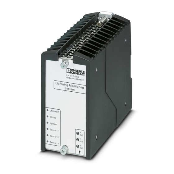
LM-S Dimensions 77,6 181,5 Lightning Monitoring System LNK/ACT 10/100 System Sensor 1 Sensor 2 Sensor 3 Figure 2-1 LM-S-A/C-3S-ETH evaluation unit Figure 2-2 LM-S-LS-H sensor 10 / 72 PHOENIX CONTACT 105005_en_02... -
Page 11: Structure Of The Evaluation Unit
Description of the LM-S lightning monitoring system Structure of the evaluation unit 2.3.1 Connections Ethernet Power Remote Figure 2-3 Connections on the bottom Sensor inputs/outputs Ethernet connection (RJ45 socket, 10/100 Mbps) Connection for the supply voltage (24 V DC, M12 circular connector) -
Page 12: Indicators
LM-S 2.3.2 Indicators Color/state Meaning LNK/ACT Green Connection established Flashing green Communication active LNK/ACT 10/100 Orange 100 Mbps 10/100 10 Mbps System System Green System is ready, measurement active Flashing green System is starting, measurement not active Sensor 1 During a firmware update: the operating system is... -
Page 13: Firmware Versions
New functions available as of firmware Version 1.7.3 – Modbus/TCP server implemented – DCP server implemented; the LM-S can be found in a network via DCP and you can modify the network address – Each entry in a lightning log csv file has an index –... -
Page 14: Licensing Information
(CD or DVD-ROM) from Phoenix Contact by contacting the After Sales Service no later than three years after delivery of the product at the addresses below. A processing charge of 50 euros will be required for this purpose. -
Page 15: Installing Sensors And The Evaluation Unit
Mount and lock the plugs according to the instructions. NOTE: Contamination of the FO connection Always protect open plugs and couplings with dust protection caps. Store the dust protec- tion caps in a sealable plastic bag. 15 / 72 105005_en_02 PHOENIX CONTACT... -
Page 16: Calibration Factor
10 mm. If the sensor is used with a different down conductor the calibration factor must be adjusted accordingly. The LM-S sensors are calibrated for direct mounting on circular down conductors with di- ameter d = 10 mm. If the sensors are used with a different down conductor, you must include an additional fac- tor in the software (see “Sensor settings”... -
Page 17: Installing Sensors
NOTE: Risk of inaccurate measurements Install the sensors outside of the area affected by external magnetic fields. Use the mount- ing inserts supplied. Fixing clips on the sensor Figure 3-2 Alignment of the sensor on the conductor 17 / 72 105005_en_02 PHOENIX CONTACT... - Page 18 LM-S Mounting on open down conductors Mounting on a flat down conductor Mounting on a circular down conductor, according to the diameter of the down conductor Figure 3-3 Mounting the sensor on an exposed down conductor • Push the two mounting inserts (2) provided into the corresponding receptacles.
- Page 19 MONTAGE ADAPTER LM-S-LS 02, Order No. 2906891 To easily mount the lightning sensor in the rotor blade of a wind turbine generator, use the mounting adapter that is available for this (MONTAGE ADAPTER LM-S-LS 02, Order No. 2906891). The assembly instructions can be found at phoenixcontact.net/qr/2906891.
-
Page 20: Connecting The Connecting Cable To The Sensor
LM-S 3.3.2 Connecting the connecting cable to the sensor To connect sensors to the evaluation unit, use connecting cable FOC-SJ:14-ST/HB02/..., Order No. 1417723. This cable can be ordered in the necessary length. However, the cable may not be shorter than 10 m or longer than 200 m. - Page 21 Install the connecting cable so that it is not squeezed or bent. Make sure that it is secured correctly and that the cable binders are sufficiently tight. The cable binder must not squeeze the cable. 21 / 72 105005_en_02 PHOENIX CONTACT...
-
Page 22: Installing The Evaluation Unit
LM-S Installing the evaluation unit 3.4.1 Safety notes WARNING: Risk of electric shock Only mount and remove the evaluation unit when the power supply is disconnected. WARNING: Risk of burns The housing surface can reach temperatures in excess of 65°C depending on the ambient temperature and the device load. -
Page 23: Mounting On A Din Rail
Use a suitable screwdriver to release the locking mechanism on the snap-on foot of the device (see Figure 3-9 E). • Hold on to the device by the housing cover and carefully tilt it upwards. • Carefully lift the device off the DIN rail. 23 / 72 105005_en_02 PHOENIX CONTACT... -
Page 24: Direct Wall Mounting
As an alternative to mounting on the DIN rail, you can mount the device on the wall of the control cabinet, for example. To do this, only the LM-S-UWA wall adapter, Order No. 2907466, may be used. This wall adapter allows the evaluation unit to be fixed directly onto a surface. -
Page 25: Connecting Sensors To The Evaluation Unit
Remove the dust protection caps on the FO ports and the connecting cable. The BFOC connectors are a sensitive part of the FO measuring path. Take care when in- stalling and mounting the BFOC connectors. Slight pre-existing damage can ultimately re- sult in irreparable damage. 25 / 72 105005_en_02 PHOENIX CONTACT... - Page 26 LM-S Figure 3-11 Connecting the connecting cable to the evaluation unit NOTE: Damage to the connecting cable Observe the minimum bending radius when installing the connecting cable, otherwise ir- reparable damage may be caused to the cable. NOTE: Risk of inaccurate measurements Install the cables in such a way that pressure or tension is at no time exerted on the cables.
-
Page 27: Connecting The Network
(SAC-4P-M12MSD/ 2,0-933, Order No. 1524307). As soon as the LM-S is ready for operation, the signal contact is closed. In the event of a system failure, the signal contact is open. It is possible to indicate measurement results and warnings via the signal contact. -
Page 28: Connecting The Voltage Supply
LM-S 3.4.7 Connecting the voltage supply NOTE: Risk of inaccurate measurements Connect the sensors to the evaluation unit first and then the 24 V DC power supply. NOTE: Increased EMC requirements (surge voltage test intensity > 0.5 kV) Take appropriate measures if increased requirements must be met regarding electromag- netic compatibility. -
Page 29: Measuring Mode
10 minutes, the operating current is switched off to protect the optical measur- ing circuit and the error is indicated. In this case, the corresponding “Sensor” LEDs and “System” LEDs light up red. Please refer to “Error messages and solutions” on page 47 for more information. 29 / 72 105005_en_02 PHOENIX CONTACT... -
Page 30: Configuring The Lm-S
The description of the web interface is based on Version 1.7.5. You can configure the LM-S lightning monitoring system via a web interface. The web inter- face can be accessed via a computer with a web browser. We recommend using Mozilla Firefox as the web browser. -
Page 31: Setting Up Or Assigning The Ip Address
If the IP address is lost, you can have the LM-S search for it via DCP. Network configuration via DHCP If you operate the LM-S in a network with a DNS server, e.g., on a router, configuration can be performed automatically. -
Page 32: Configuration Procedure
LM-S Configuration procedure Table 4-1 Overview Menu Step by step • Enter the IP address of the evaluation unit in the address bar of the web browser. The default address is 10.0.0.100. Updating the firmware Firmware Page 43 • Make sure you always use the latest firmware. -
Page 33: Access Via Web Interface
Configuring the LM-S Access via web interface • Enter the IP address of the evaluation unit in the address bar of the web browser. The default address is 10.0.0.100. After entering the IP address in the browser, the “Status” page is displayed. You can now start setting up the system. -
Page 34: Querying The Status
LM-S Querying the status Status Displays the status of the LEDs on the front of the housing. You can determine the state of the evaluation unit based on the current LED driving cur- rents. Front LED Displays the status of the LEDs located on the evaluation unit (see “Indicators”... - Page 35 NOTE: Only disable interfaces that are not re- quired when you have established stable com- OPC-UA munication with the LM-S. Otherwise there is a risk that you will be locked out accidentally. You may then no longer be able to establish commu- Telnet nication.
-
Page 36: Evaluating Lightning Current Characteristics
LM-S Evaluating lightning current characteristics Lightning log An entry is stored in a log file together with a timestamp and all measured values for every lightning strike. Up to 500 lightning events are stored in the log file. On each subsequent lightning event the oldest data record is deleted. - Page 37 Configuring the LM-S Characteristics of a lightning event I [kA] Peak current Largest di/dt di/dt Trigger level: 5 kA Complete data record: 1 s T [μs] Trigger point Figure 4-1 Example for a lightning event 37 / 72 105005_en_02 PHOENIX CONTACT...
-
Page 38: System Settings
LM-S System settings Measurement settings Specify at what lightning current strength a measured value should be acquired. Specify how much time before and after the lightning strike should be included. Trigger level Default: 15 kA, setting range: 5 kA ... 400 kA... - Page 39 Configuring the LM-S Signal contact U [V] 0.5 s ...10 s 0.5 s ... 10 s 24 V >500 ms >500 ms >500 ms (closed) >10 s (open) Start Light- System fail- Warning: T [s] phase ning ure/disabled maintenance Figure 4-2 Function of the floating signal contact “System ready”...
-
Page 40: Sensor Settings
This factor is dependent on the distance between the measuring path in the sensor and the down conductor, and on the geometry of the down conductor. To deter- mine this factor, contact Phoenix Contact. • Confirm your entry with “Save”. The change is applied im- mediately. -
Page 41: Network Settings
Configuring the LM-S Network settings Network settings You can change the IP address of the evaluation unit here. Please note that the network settings on the computer may also need to be changed. The computer and evaluation unit must be in the same IP subnetwork. -
Page 42: Clock Settings
LM-S Clock settings Set clock Enter the current time and date. This is important in order to accurately record when light- ning strikes occur. We recommend setting the UTC time zone. Coordinated universal time avoids jumps in the time stamps and misunderstandings. -
Page 43: Firmware Update
Configuring the LM-S 4.10 Firmware update Update firmware The latest firmware updates are available at phoenixcontact.net/qr/2800618. Updating the firmware version We recommend using Mozilla Firefox to update the firmware. Click on the “Browse...” button and select the desired file (e.g., LMS_up- date_175.sh). - Page 44 LM-S Collect – Information on device status is provided here. Mea- Debug surement data are not included in this. Reset to default values You can reset the device to default settings via the Update function. To do so, perform steps 1-3 with file “LMS_factor-reset_175.sh”. By performing this update, all settings will be lost.
-
Page 45: Assigning Ip Addresses (Dcp)
You can assign the IP address of the LM-S using NetNames+. NetNames+ is part of PC Worx. It is a software package from Phoenix Contact for PC-based automation solutions. A free demo version is available: PC WORX DEMO, Order No. -
Page 46: Service And Maintenance
Maintenance work may have to be carried out on the LM-S where the device must remain switched on, e.g., for electrical testing. In this case, we recommend backing up the event log (log file) in the system beforehand and restarting the LM-S once the work has been com- pleted. -
Page 47: Error Messages And Solutions
10 minutes, the operating current is switched off to protect the optical measuring circuit and the error is indicated. The corre- sponding “Sensor” LED and the “System” LED light up red. Refer to Table 5-1 for possible solutions. 47 / 72 105005_en_02 PHOENIX CONTACT... -
Page 48: Replacing Components
LM-S Replacing components WARNING: Before any intervention in the installation, disconnect the power to the LM-S evaluation unit. NOTE: Avoid contaminating the plug-in connections. 5.3.1 Replacing sensors • Before any intervention in the installation, disconnect the power to the LM-S evaluation unit. -
Page 49: Cleaning Connectors
Carefully clean the contacts on both sides of the connection every time you remove the plug-in connection. We recommend cleaning with the FOC-TOOL-FERRULECLEANER-2.50 ferrule cleaner, Order No. 1407029. 49 / 72 105005_en_02 PHOENIX CONTACT... -
Page 50: Modbus Protocol
The LM-S supports Modbus/TCP with the following features. Modbus interface The Modbus interface on the LM-S supports Modbus communication (TCP port 502). The LM-S supports up to five simultaneous Modbus/TCP connections. The connections can access different addresses at the same time. A separate instance is configured for each connection with the contents of the device registers. -
Page 51: Modbus Register Tables
B1: Saves registers 7 – 10 (device time and date) B3: Saves all other registers (except registers 7 – 10) B15: LM-S restart (reboot) Example: writing 0x1 reloads all system values in the registers SNTP Enable/Disable Read/Write... -
Page 52: Monitoring System Settings
LM-S 6.2.2 Monitoring system settings Table 6-3 Monitoring system settings Register Function Access Format Description Trigger Level Read/Write Integer [5 – 400] Trigger level in [kA] (values from 5 kA ... 400 kA supported) Pre Trigger Read/Write Integer with 1 deci- Pre trigger setting in [s] (values from mal [0.1 –... -
Page 53: Network Settings
0x112233445566 = MAC address 11:22:33:44:55:66 Changes to the network settings are applied automatically by the device when saved. This can take a few moments. Afterwards, the device can only be reached via the new settings. 53 / 72 105005_en_02 PHOENIX CONTACT... -
Page 54: Status Settings
3 = “green” status 4 = “flashing green” status During the LM-S start phase, the status messages are not yet up to date. The value for all registers is 65535, and only during operating system start. The “System” LED lights up or- ange. -
Page 55: Sensor Settings
A restart is automatically triggered when the sensor settings are changed. The software on the system is restarted. The sensors are not calibrated again. The restart can take a few mo- ments. The restart is triggered when saving (request via register 11, bit 3, see Page 51). 55 / 72 105005_en_02 PHOENIX CONTACT... -
Page 56: Interface Service Settings
NOTE: Only disable interfaces that are not required when you have established stable communication with the LM-S. Otherwise there is a risk that you will be locked out acci- dentally. You may then no longer be able to establish communication. -
Page 57: Event Log Settings
The request is executed when saving (request via register 11). The result of the request is displayed in registers 1100 to 1135. A new client connection has the default value of the newest entry (register 1000). 57 / 72 105005_en_02 PHOENIX CONTACT... -
Page 58: Data In The Event Log (Lightning Data)
LM-S 6.2.8 Data in the event log (lightning data) Table 6-9 Data in the event log (lightning data) Register Function Access Format Description 1100 Lightning Dataset Index Read only Integer Index of the data in the event log (light- ning data) in registers 1101 to 1135. - Page 59 Charge of the evaluated lightning cur- rent [As] 1135 Charge Sensor 3 LSB Read only Float LSB “Float” format corresponds to IEEE 754 “big endian format - float binary 32”. Two registers (MSB/LSB) have a 32-bit value. 59 / 72 105005_en_02 PHOENIX CONTACT...
-
Page 60: Opc Ua Server
In the case of data exchange, the data is authenticated, authorized, and encrypted by a sig- nature with X.509v3 certificates. The LM-S starts the OPC UA server with the setting that every client is accepted. For the purposes of identification, a self-signed certificate is present on the device (SHA1 RSA al- gorithm with 2048 bits). -
Page 61: Establishing A Secure Connection
Trusted means that the client is entered in the “Trust List”. Use your own certificate for a secure connection. All devices which you want to authorize to access the LM-S should be declared as trusted. To do this, enter the trusted devices in the “True List”. -
Page 62: Variables For The Opc Ua Server
LM-S Variables for the OPC UA server 7.4.1 General settings Table 7-1 General settings Name Node Access Data type Description type Type definition Firmware_version Variable Read only String Version of the installed firmware BaseDataVariable Example: 1.7.5 Current_time Variable Read only UtcTime... -
Page 63: Monitoring System Settings
The software on the system is restarted. The sensors are not calibrated again. The restart can take a few moments. The restart is triggered when saving (request via “Set_measurement_settings” method). For additional information on the monitoring system settings, refer to “System settings” on page 38. 63 / 72 105005_en_02 PHOENIX CONTACT... -
Page 64: Network Settings
LM-S 7.4.3 Network settings Table 7-3 Network settings Name Node type Access Data type Description Type definition Device name Variable Read String Example: SNR 1234567890 only BaseDataVariable IP_address Variable Read String Example: 10.0.0.100 only BaseDataVariable Netmask Variable Read String Example: 255.255.255.0... -
Page 65: Information On The Status
4 = “flashing green” status BaseDataVariable During the LM-S start and warm-up phase, the status messages are not yet up to date. The value for all variables is 65535 in this state. The same also applies during a system restart (reboot) or measurement routine (restart). -
Page 66: Sensor Settings
LM-S 7.4.5 Sensor settings Table 7-5 Sensor settings Name Node Access Data type Description type Type definition Calibration_factor_sensor_1 Variable Read Double Calibration factor for only the sensor BaseDataVariable Calibration_factor_sensor_2 Variable Read Double only BaseDataVariable Calibration_factor_sensor_3 Variable Read Double only BaseDataVariable... -
Page 67: Interface Service Settings
Read ServiceStatusType 4 = Service has an error only BaseDataVariable FTP_status Variable Read ServiceStatusType only BaseDataVariable Telnet_status Variable Read ServiceStatusType only BaseDataVariable SSH_status Variable Read ServiceStatusType only BaseDataVariable DCP_status Variable Read ServiceStatusType only BaseDataVariable 67 / 72 105005_en_02 PHOENIX CONTACT... - Page 68 NOTE: Only disable interfaces that are not required when you have established stable communication with the LM-S. Otherwise there is a risk that you will be locked out acci- dentally. You may then no longer be able to establish communication.
-
Page 69: Event Log Settings (Lightning Data)
Time and date of the last lightning event only entered BaseDataVariable Example: 2000-01-01T00:00:00.000Z Lightning_count Variable Read UInt32 Number of lightning events measured so only BaseDataVariable Log_data Variable Read LightningLogDataType Measured values of measured lightning only BaseDataVariable events in a variable structure 69 / 72 105005_en_02 PHOENIX CONTACT... -
Page 70: Lightninglogdatatype" Variable Structure (Lightning Data)
LM-S 7.4.8 “LightningLogDataType” variable structure (lightning data) Table 7-8 “LightningLogDataType” variable structure (lightning data) Name Node Access Data type Description type Type definition Timestamp Variable Read UtcTime Time and date of the lightning event only BaseDataVariable Example: 2000-01-01T00:00:00.000Z Trigger_mask Variable... - Page 71 The receipt of technical documentation (in particular user documentation) does not constitute any further duty on the part of Phoenix Contact to furnish information on modifications to products and/or technical documentation. You are responsible to verify the suitability and intended use of the products in your specific application, in particular with regard to observing the applicable standards and regulations.
- Page 72 Should you have any suggestions or recommendations for improvement of the contents and layout of our manuals, please send your comments to: tecdoc@phoenixcontact.com 72 / 72 PHOENIX CONTACT GmbH & Co. KG • Flachsmarktstraße 8 • 32825 Blomberg • Germany phoenixcontact.com...
- Page 74 PHOENIX CONTACT GmbH & Co. KG Flachsmarktstraße 8 32825 Blomberg, Germany Phone: +49 5235 3-00 Fax: +49 5235 3-41200 E-mail: info@phoenixcontact.com phoenixcontact.com...
Need help?
Do you have a question about the LM-S and is the answer not in the manual?
Questions and answers