Table of Contents
Advertisement
Quick Links
Advertisement
Table of Contents

Related Manuals for Phoenix Contact EEM-MA200


Summary of Contents for Phoenix Contact EEM-MA200
- Page 1 INTERFACE User manual UM EN EEM-MA200/250 Order No.: —...
- Page 3 INTERFACE User manual Energy meter for single, two, and three-phase networks 2011-06-08 Designation: UM EN EEM-MA200/250 Revision: — Order No.: This user manual is valid for: Designation Revision Order No. EEM-MA200 2901362 EEM-MA250 2901363 104415_en_00 PHOENIX CONTACT...
- Page 4 User group of this manual The use of products described in this manual is oriented exclusively to Phoenix Contact accepts no liability for erroneous handling or damage to products from Phoenix Contact or third-party products resulting from disregard of information contained in this user manual.
- Page 5 The receipt of technical documentation (in particular data sheets, installation instructions, user manuals, etc.) does not constitute any further duty on the part of Phoenix Contact to furnish information on alterations to products and/or technical documentation. Any other agreement shall only apply if expressly confirmed in writing by Phoenix Contact.
- Page 6 Phoenix Contact. Violators are liable for damages. Phoenix Contact reserves all rights in the case of patent award or listing of a registered design. Third-party products are always named without reference to patent rights. The existence of such rights shall not be excluded.
-
Page 7: Table Of Contents
Communication speed (EEM-MA250) .............. 5-13 5.10 Parity (EEM-MA250)..................5-14 5.11 Stop bits (EEM-MA250)..................5-15 5.12 Configuring the LCD ..................5-16 5.13 Operating hours counter................... 5-17 5.14 Digital input....................... 5-18 5.15 Changing the configuration mode access code..........5-19 104415_en_00 PHOENIX CONTACT... - Page 8 EEM-MA200/EEM-MA250 5.16 Displaying the software version and serial number..........5-20 5.17 Exiting configuration mode ................5-20 Operation – Displaying measured values ................6-1 Displaying currents and the total harmonic distortion (THD) .................. 6-2 Displaying voltages, frequency, and the total harmonic distortion (THD)................6-4 Displaying the power and power factors .............
-
Page 9: Safety Notes
16 A) in the installation. ≤ – Observe the maximum permissible values for the device supply (277 V AC), mains frequency (50/60 Hz), maximum voltage at connection terminal blocks (519 V AC phase/phase or 300 V AC phase/neutral conductor). 104415_en_00 PHOENIX CONTACT... -
Page 10: Device Description
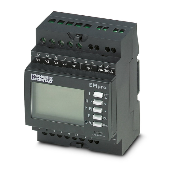
EEM-MA200/EEM-MA250 Device description The EEM-MA200/EEM-MA250 is a highly accurate multifunction measuring device for measuring electrical parameters in low-voltage systems up to 500 V AC. It supports the measurement, counting, and display of all electrical parameters and is mounted on a 35 mm DIN rail according to EN 60715. -
Page 11: Displaying Measured Values
Maximum value, average value of real power (ΣP), reactive power (ΣQ), apparent power (ΣS) – Total power factor (ΣPF) – Power factor per phase (PF1, PF2, PF3) E button – Positive real energy (EA+) – Positive reactive energy (ER+) h/°C button – Operating hours – Ambient temperature 104415_en_00 PHOENIX CONTACT... -
Page 12: Characteristics
EEM-MA200/EEM-MA250 Characteristics Current measurement Primary current transformer 9999 A (TRMS) Secondary current transformer Minimum measured current 5 mA Display 0 ... 9999 A Intrinsic consumption < 0.3 VA Measured value update Accuracy 0.2% (10 ... 110% I Continuous overload Short-term overload... -
Page 13: Operating And Indication Elements
Pushbuttons with dual functionality: Normal mode: Display measured values Programming mode: Change configuration Backlit LCD Display measured values in relevant conductor Measured value Unit Status indicator: Energy recording RS-485 communication interface (EEM-MA250) Status indicator: Communication active (EEM-MA250) 104415_en_00 PHOENIX CONTACT... -
Page 14: Mounting And Installation
EEM-MA200/EEM-MA250 Mounting and installation Avoid being in close proximity to systems that can generate electromagnetic interference. In addition, avoid mechanical vibrations with acceleration rates greater than 1g (9.81 m/s2) at frequencies below 60 Hz. Mounting The device is snapped onto a DIN rail in the control cabinet. The mounting position can be freely selected, but will be determined by the readability of the LCD. -
Page 15: Pin Assignment
Maximum tightening torque for the relevant screws: 0.4 Nm. DANGER: Risk of electric shock If the device is disconnected, the secondary sides of the relevant current transformers must be short circuited. A URTK6 transformer disconnect terminal block (Order No. 3026272) can be used for this. 104415_en_00 PHOENIX CONTACT... -
Page 16: Termination Resistor
When selecting the current transformer, the secondary nominal current must be 5 A. The primary nominal current is determined by the current consumption of the load. Appropriate PACT current transformers can be found in the Phoenix Contact INTERFACE catalog. DANGER: Risk of electric shock Only install current transformers and corresponding measuring devices when the power supply is disconnected. -
Page 17: Three-Phase Network With Asymmetrical Load (4Nbl)
V1 V2 V3 VN S1 S2 S1 S2 S1 S2 Figure 4-4 Three-phase network with asymmetrical load (4NBL) 1 Supply voltage range: 200 … 277 V AC 2 Fuse: 0.5 A gG/BS 88 2A gG/0.5 A class CC 104415_en_00 PHOENIX CONTACT... -
Page 18: Three-Phase Network With Asymmetrical Load (3Nbl)
EEM-MA200/EEM-MA250 4.5.3 Three-phase network with asymmetrical load (3NBL) 1 = Fuse 0.5 gG / 0.5 A Class CC 1 1 1 V1 V2 V3 VN S1 S2 S1 S2 S1 S2 Figure 4-5 Measurement via 3 current transformers 1 = Fuse 0.5 gG / 0.5 A Class CC... -
Page 19: Three-Phase Network With Symmetrical Load (3Bl/4Bl)
200 … 277 V AC 2 Fuse: 0.5 A gG/BS 88 2A gG/0.5 A class CC The solution with one current transformer reduces the accuracy of phases by 0.5%, whereby their current is calculated vectorially (without current transformer). 104415_en_00 PHOENIX CONTACT... -
Page 20: Two-Phase Network (2Bl)
EEM-MA200/EEM-MA250 4.5.5 Two-phase network (2BL) 1 = Fuse 0.5 gG / 0.5 A Class CC V1 V2 V3 VN S1 S2 S1 S2 S1 S2 Figure 4-9 Two-phase network (2BL) 1 Supply voltage range: 200 … 277 V AC 2 Fuse: 0.5 A gG/BS 88 2A gG/0.5 A class CC... -
Page 21: Configuration
Configuration Configuration The device can be configured via pushbuttons. The configuration is shown in the following subsections. To configure the EEM-MA200/EEM-MA250, press the gray buttons consecutively, as described in the relevant example. Button Description PROG Open configuration mode (press and hold for 3 seconds) ▲... - Page 22 EEM-MA200/EEM-MA250 Configuration mode: Mains types: 4NBL; 3NBL; 4BL; 3BL; 2BL; 1BL Set primary current strenght Current transformer: Measuring time for currents to 20' min; 30' min; 60' min; 2'‘ sec; 5' min; 8' min; 10' min; 15' min calculate MAX values: Measuring time for real power to 20' min;...
-
Page 23: Configuration Mode (Prog) - Code 100
Follow the instructions and enter "Code 100". • Confirm with "OK". TEST P PF °C 3 seconds PROG TEST P PF °C PROG TEST P PF °C PROG TEST P PF Confirm °C PROG Figure 5-2 Switching to configuration mode 104415_en_00 PHOENIX CONTACT... -
Page 24: Example: Configuring The Device For A Three-Phase Network With Asymmetrical Load
EEM-MA200/EEM-MA250 Example: Configuring the device for a three-phase network with asymmetrical load NET = 3NBL TEST P PF °C PROG TEST 3NBL P PF 4NBL °C PROG TEST P PF Confirm °C PROG Figure 5-3 Setting a three-phase network with asymmetrical load (3NBL) -
Page 25: Current Transformers
PROG TEST P PF °C PROG TEST P PF Confirm °C PROG Figure 5-4 Setting the transformer ratio CT = 1200/5A The current transformer output for the secondary side is always 5 A and cannot be changed. 104415_en_00 PHOENIX CONTACT... -
Page 26: Current Measuring Time
EEM-MA200/EEM-MA250 Current measuring time This value specifies over which period the currents are to be measured for determining the maximum values. Example: Measuring time of 20 minutes tIME I = 20 min. TEST P PF °C PROG 20 min. TEST 30 min. -
Page 27: Power Measuring Time
P PF °C PROG 20 min. TEST 30 min. 60 min. 2 sec. P PF 5 min. 8 min. 10 min. °C PROG 15 min. TEST P PF Confirm °C PROG Figure 5-6 Setting the power measuring time 104415_en_00 PHOENIX CONTACT... -
Page 28: Reset
EEM-MA200/EEM-MA250 Reset You can reset the last measured values as shown in the following example. Example: rSET = EA (real energy) TEST P PF °C PROG P, maximum power value TEST EA, real energy (kWh) ER, reactive energy (kVArh) I, maximum current value P PF °C... -
Page 29: Output Type
P PF °C PROG ER, reactive energy (kVArh) TEST ALAr, alarm output Cd, control relay state via MODBUS EA, real energy (kWH) P PF °C PROG TEST P PF °C PROG Confirm Figure 5-8 Setting the output type 104415_en_00 PHOENIX CONTACT... -
Page 30: Output Pulse Value
EEM-MA200/EEM-MA250 5.7.1 Output pulse value Enter the output pulse value as shown in the following example (for reactive energy (ER) and real energy (EA) only; pulse per unit). TEST P PF °C PROG 1 x à 10: 10 kwh (EA)/10 kvarh (ER) TEST 2 x à... -
Page 31: Pulse Output Length
Enter the pulse output length as shown in the following example (for reactive energy (ER) and real energy (EA) only; in ms). TEST P PF °C PROG TEST P PF °C PROG TEST P PF °C PROG Confirm 5-11 104415_en_00 PHOENIX CONTACT... -
Page 32: Communication Address (Eem-Ma250)
EEM-MA200/EEM-MA250 Communication address (EEM-MA250) Enter the communication address as shown in the following example (1 ... 255). TEST P PF °C PROG 0 ... 2 TEST P PF °C PROG TEST P PF °C PROG 0 ... 9 TEST P PF °C... -
Page 33: Communication Speed (Eem-Ma250)
Communication speed (EEM-MA250) Enter the communication speed as shown in the following example. TEST P PF °C PROG TEST 19.2 P PF 38.4 °C PROG TEST P PF Confirm °C PROG Figure 5-10 Setting the communication speed 5-13 104415_en_00 PHOENIX CONTACT... -
Page 34: Parity (Eem-Ma250)
EEM-MA200/EEM-MA250 5.10 Parity (EEM-MA250) Enter the parity as shown in the following example. TEST P PF °C PROG TEST Even P PF °C PROG TEST P PF Confirm °C PROG Figure 5-11 Setting the parity 5-14 PHOENIX CONTACT 104415_en_00... -
Page 35: Stop Bits (Eem-Ma250)
5.11 Stop bits (EEM-MA250) Enter the stop bits as shown in the following example. TEST P PF °C PROG TEST P PF °C PROG TEST P PF Confirm °C PROG Figure 5-12 Setting the stop bits 5-15 104415_en_00 PHOENIX CONTACT... -
Page 36: Configuring The Lcd
EEM-MA200/EEM-MA250 5.12 Configuring the LCD The LCD lighting can be configured in various ways. Configuration options The display is illuminated when: – Supply voltage is present (AUX) – Current is being measured (I) – Voltage is being measured (U) In the case of the AUX setting (supply voltage is present), the display automatically goes out after 2 minutes. -
Page 37: Operating Hours Counter
TEST P PF °C PROG I, input current TEST U, input voltage INPt, digital input AUX, supply voltage P PF °C PROG TEST P PF Confirm °C PROG Figure 5-14 Setting a voltage-dependent operating hours counter 5-17 104415_en_00 PHOENIX CONTACT... -
Page 38: Digital Input
EEM-MA200/EEM-MA250 5.14 Digital input Configure the digital input as shown in the following example. TEST P PF °C PROG LInE, save the real and reactive TEST energy of two different loads tArF, save the real and reactive energy of two different tariffs (e.g., day and... -
Page 39: Changing The Configuration Mode Access Code
In order to change the configuration mode access code, proceed as follows: Example: COdE = 300 TEST P PF °C PROG TEST P PF 10 x °C PROG TEST P PF Confirm °C PROG Figure 5-16 Changing the configuration mode access code 5-19 104415_en_00 PHOENIX CONTACT... -
Page 40: Displaying The Software Version And Serial Number
EEM-MA200/EEM-MA250 5.16 Displaying the software version and serial number Switch to programming mode. TEST P PF °C SOFt PROG Example: SOFt = 101 Example: E = 09250003 Figure 5-17 Displaying the software version and serial number 5.17 Exiting configuration mode To exit configuration mode, press and hold down the "PROG"... -
Page 41: Operation - Displaying Measured Values
By pressing the appropriate pushbutton several times, further measured values can be displayed within the selected menu (see also "Displaying measured values" on page 2-2). The figures in the following subsections explain the various measured value displays obtained by pressing the pushbuttons several times. 104415_en_00 PHOENIX CONTACT... -
Page 42: Displaying Currents And The Total Harmonic Distortion (Thd)
EEM-MA200/EEM-MA250 Displaying currents and the total harmonic distortion (THD) Press button: – Currents in conductors (I1, I2, I3) – Current in neutral conductor (IN) – Maximum current value (I1, I2, I3) PHOENIX CONTACT 104415_en_00... - Page 43 Operation – Displaying measured values – Maximum neutral conductor cur- rent value (IN) – Total harmonic distortion of cur- rents THD I1, THD I2, THD I3 (%) 104415_en_00 PHOENIX CONTACT...
-
Page 44: Displaying Voltages, Frequency, And The Total Harmonic Distortion (Thd)
EEM-MA200/EEM-MA250 Displaying voltages, frequency, and the total harmonic distortion (THD) Press button: – Phase/phase conductor voltages (U12, U23, U31) – Phase/N conductor voltages (V1, V2, V3) – Frequency (F) – Total harmonic distortion of phase/phase conductor voltage THD U12, THD U23, THD U31 (%) - Page 45 Operation – Displaying measured values – Total harmonic distortion of phase/N conductor voltage THD V1, THD V2, THD V3 (%) 104415_en_00 PHOENIX CONTACT...
-
Page 46: Displaying The Power And Power Factors
EEM-MA200/EEM-MA250 Displaying the power and power factors Press button: P PF – Total real power (ΣP) – Total reactive power (ΣQ) – Total apparent power (ΣS) – Real power per phase (P1, P2, P3) – Reactive power per phase (Q1, Q2, Q3) –... - Page 47 Operation – Displaying measured values – Total power factor (ΣPF) = Inductive – Power factor per phase (PF1, PF3) = Inductive – Power factor per phase (PF2) = Capacitive 104415_en_00 PHOENIX CONTACT...
-
Page 48: Displaying The Energy
EEM-MA200/EEM-MA250 Displaying the energy Press button: – Absorbed (positive) real energy (EA+) – Absorbed (positive) reactive energy (ER+) – Real energy tariff 1 – Real energy tariff 2 – Reactive energy tariff 1 PHOENIX CONTACT 104415_en_00... - Page 49 Operation – Displaying measured values – Reactive energy tariff 2 104415_en_00 PHOENIX CONTACT...
-
Page 50: Displaying The Operating Hours And Temperature
EEM-MA200/EEM-MA250 Displaying the operating hours and temperature Press button: °C – Operating hours – Temperature 6-10 PHOENIX CONTACT 104415_en_00... -
Page 51: Function Test
The connections (without neutral conductors) are checked using the 4BL/3BL/2BL/1BL setting. – All connections (with neutral conductors) are checked using the 4NBL and 3NBL setting. The following errors are displayed by the EEM-MA200/EEM-MA250: Error Description Err 0 No error Err 1/2/3... -
Page 52: Calling The Function Test
EEM-MA200/EEM-MA250 Calling the function test Press button: The test menu is opened when the "test button" is pressed and held down for at least three seconds. TEST The function test is started automatically if a test has not yet been performed. -
Page 53: Automatic Correction Of Current Connections
PROG TEST • Activate correction P PF °C PROG TEST • Confirm entry P PF °C PROG TEST • Exit function test, display mode P PF °C PROG 3 seconds Figure 7-4 Automatic correction of current connections 104415_en_00 PHOENIX CONTACT... -
Page 54: Repeat Function Test (Started Manually)
EEM-MA200/EEM-MA250 Repeat function test (started manually) This menu is only displayed if the device has already been tested. It is possible to perform an entirely new test, as shown below. TEST • Call function test 3 seconds P PF °C... -
Page 55: Troubleshooting
Check the current input – Check the configuration of the current transformer ratios Incorrect display of power, power factor, and energy – Start the function test No display of phases – Check the configuration of the device (see Page 5-4) 104415_en_00 PHOENIX CONTACT... - Page 56 EEM-MA200/EEM-MA250 PHOENIX CONTACT 104415_en_00...
-
Page 57: Modbus Basics
Example: Response from a slave (initiated by slave) Slave Function Number of bytes High CRC 16 address register value register value 0011 IDDD 2FAF Table 9-3 Example: Write device parameters Slave Function High address High register CRC 16 address address value register value 7F8D 104415_en_00 PHOENIX CONTACT... - Page 58 EEM-MA200/EEM-MA250 Each bus device must have a unique address. Slave address 0 is reserved for a broadcast. Function codes in MODBUS Several function codes are defined in MODBUS. They are as follows: Function code Name Abbrevia- Description tion 03 hex...
-
Page 59: 10 Modbus Register Tables
Decimal Hexa- Number of Designation Unit Register address decimal data access address words 50512 C550 Hour: Operating hours counter h/100 50514 C552 U12: Conductor voltage (1-2) V/100 50516 C554 U23: Conductor voltage (2-3) V/100 10-1 104415_en_00 PHOENIX CONTACT... - Page 60 EEM-MA200/EEM-MA250 Table 10-2 C550 hex: Display current main measured values based on current transformer (taking into consideration transformation ratios)[...] Decimal Hexa- Number of Designation Unit Register address decimal data access address words 50518 C556 U31: Conductor voltage (3-1) V/100 50520...
- Page 61 3915 Response from the EEM-MA250: The register contents correspond to a positive real energy of 177,645 kWh Slave address Function Number of bytes High CRC 16 register value register value 0011 IDDD 2FAF 7645 10-3 104415_en_00 PHOENIX CONTACT...
- Page 62 EEM-MA200/EEM-MA250 Table 10-4 C750 hex: Display average values based on current transformer over the set measurement duration (taking into consideration transformation ratios) Decimal Hexadecimal Number Designation Unit Register address address of data access words 51024 ... 51068 C750 ... C77C 46...
- Page 63 EA+: Total positive real energy since startup (cannot be reset) 51312 C870 Not available 51313 C871 EA-: Total negative real energy since startup (cannot be reset) 51314 C872 Not available Range: 35 words (decimal) or 23 words (hexadecimal) 10-5 104415_en_00 PHOENIX CONTACT...
- Page 64 EEM-MA200/EEM-MA250 Example: In order to display all the values in Table C850 with a length of 35 words with a single request, the following data sequence must be sent: Slave Function High No. of high No. of CRC 16 address...
- Page 65 Not available – 57350 E006 Not available – 57351 E007 Not available – 57352 E008 Not available – 57354 E00A Not available – 57355 E00B Not available – Range: 12 words (decimal) or C words (hexadecimal) 10-7 104415_en_00 PHOENIX CONTACT...
- Page 66 After changing the configuration parameters, the following command can be used to save them Slave Function High High register Low register CRC 16 address address address value value 7F8E The response from the EEM-MA200/EEM-MA250 is identical to the message sent. 10-8 PHOENIX CONTACT 104415_en_00...
- Page 67 The following data sequence can be used to reset all saved values: Slave Function High No. of No. of CRC 16 address address address high words low words 84BE The response from the EEM-MA250 is identical to the message sent. 10-9 104415_en_00 PHOENIX CONTACT...
- Page 68 EEM-MA200/EEM-MA250 Table 10-14 8D50 hex: Display last alarm at digital output DO OUT Decimal Hexa- Number Designation Unit Register address decimal of data access address words 36176 8D50 OUT 1 Current alarm, lower threshold (output types): 0: No alarm 0: /...
- Page 69 9: 900 ms 36361 8E09 Operating hours counter: 1: AUX: Activated when supply voltage is present 2: I: Activated when threshold value is set (input current) 3: U: Activated when threshold value is set (input voltage) 10-11 104415_en_00 PHOENIX CONTACT...
- Page 70 EEM-MA200/EEM-MA250 Table 10-15 8E00 hex: Configuration of measuring device [...] Decimal Hexa- Number Designation Unit Register address decimal of data access address words 36362 8E0A Operating hours counter threshold value (current/voltage) 36363 8E0B DO OUT Alarm output (only for output type ALAr):...
-
Page 71: 11 Technical Data
30 V DC Current carrying capacity 27 mA EEM-MA250 communication interface RS-485 MODBUS 2.4 ... 38.4 kbps RTU/JBUS Supply Supply voltage range 200 … 277 V AC Nominal power consumption 5 VA Display Type Backlit LCD Refresh 11-1 104415_en_00 PHOENIX CONTACT... - Page 72 Dimensions H/W/D 90 x 72 x 64 mm Degree of protection Front IP52 Back IP30 Weight 215 g (EEM-MA200) 211 g (EEM-MA250) Electrical isolation EEM-MA200 EEM-MA250 Rated insulation voltage 300 V AC (EN 61010-1) Voltage input/supply (U-IN/POW) Safe isolation (EN 61010-1)
- Page 73 Immunity to voltage dips, short interruptions, and voltage IEC 61000-4-11 variations Conducted and radiated noise emission according to EN 55011 Class B Conformance with Low Voltage Directive 2006/95/EC Electrical safety for electrical equipment for measurement, EN 61010-1 control, regulation, and laboratory use 11-3 104415_en_00 PHOENIX CONTACT...
-
Page 74: A Abbreviations
Save real and reactive energy of two different tariffs (e.g., day and nighttime tariff) Total harmonic distortion tIME I Measuring time to determine the maximum current values tIME P Measuring time to determine the maximum power values TRMS True r.m.s. value measurement (True Root Mean Square) _en_00 104415 PHOENIX CONTACT... - Page 75 Abbreviations Operating hours counter _en_00 104415 PHOENIX CONTACT...
Need help?
Do you have a question about the EEM-MA200 and is the answer not in the manual?
Questions and answers