Table of Contents
Advertisement
Advertisement
Table of Contents

Related Manuals for Phoenix Contact TC MOBILE I/O Series


Summary of Contents for Phoenix Contact TC MOBILE I/O Series
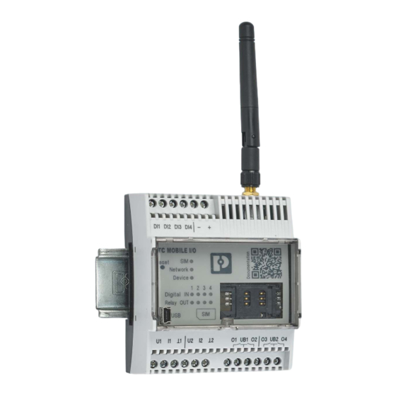
- Page 1 Remote monitoring via mobile network User manual UM EN TC MOBILE I/O...
- Page 2 2903807 TC MOBILE I/O X200 AC X200 AC 2903806 TC MOBILE I/O X200-4G AC X200-4G AC 1038568 TC MOBILE I/O X300 AC X300 AC 2903808 PHOENIX CONTACT GmbH & Co. KG • Flachsmarktstraße 8 • 32825 Blomberg • Germany phoenixcontact.com...
-
Page 3: Table Of Contents
Access via the web browser is not possible............40 The content is not displayed correctly in the web browser ........44 After use ..........................47 Maintenance and servicing ..................47 Device replacement.....................47 Device failure and repair ..................47 Disposal.......................48 3 / 70 107812_en_02 PHOENIX CONTACT... - Page 4 Technical data .........................49 Ordering data.......................49 Accessories ......................49 Comparison of product features ................50 Technical data .....................53 Conformity ......................57 Load curves of the relay outputs ................60 FCC approval (2G devices) ......................61 Appendixes..........................63 List of figures .......................63 Index........................65 4 / 70 PHOENIX CONTACT 107812_en_02...
-
Page 5: For Your Safety
The use of products described in this manual is oriented exclusively to electrically skilled persons or persons instructed by them. The users must be familiar with the relevant safety concepts of automation technology as well as applicable standards and other regulations. 5 / 70 107812_en_02 PHOENIX CONTACT... -
Page 6: Field Of Application Of The Product
“Use outside of Europe” on page Operation of the wireless system is only permitted if accessories available from Phoenix Contact are used. The use of other accessory components could invalidate the operating license. You can find the approved accessories for this wireless system listed with the product at phoenixcontact.net/products. -
Page 7: Safety Notes
It must be possible to disconnect the device from the power supply. Install an appro- priate disconnecting device (fuse, miniature circuit breaker, etc.) for this purpose. – During electrical installation, current standards and regulations must be complied with, and installation must be carried out by an expert. 7 / 70 107812_en_02 PHOENIX CONTACT... -
Page 8: Installation Notes For The 2G Devices
The switches of the device that can be accessed may only be actuated when the power supply to the device is disconnected. • Observe the derating information in the technical documentation (see “Derating, maximum ambient temperature”). 8 / 70 PHOENIX CONTACT 107812_en_02... -
Page 9: Installation Notes For The 4G Devices
The IP20 protection (IEC 60529/EN 60529) of the device is intended for use in a clean and dry environment. The device must not be subject to mechanical strain and/or thermal loads, which exceed the limits described. 9 / 70 107812_en_02 PHOENIX CONTACT... -
Page 10: Transport And Unpacking
Protected from unauthorized access – Protected from harmful environmental influences such as UV light – Temperature range: -40°C ... +85°C – Up to 2,000 m above sea level – Permissible humidity: 0% ... 95% 10 / 70 PHOENIX CONTACT 107812_en_02... -
Page 11: Checking The Delivery
Damaged packaging is an indicator of potential damage to the device that may have occurred during transport. This could result in a malfunction. • Submit claims for any transport damage immediately, and inform Phoenix Contact or your supplier as well as the shipping company without delay. •... - Page 12 TC MOBILE I/O... 12 / 70 PHOENIX CONTACT 107812_en_02...
-
Page 13: Installation
– Lighting control systems, remote switching devices – Elevators, gates – Alarm technology and building services – HVAC technology – Battery monitoring (up to 60 V) – Railway applications in accordance with EN 50121-4 13 / 70 107812_en_02 PHOENIX CONTACT... - Page 14 Standard mini SIM card, LTE-capable – Compact design: 4HP in accordance with DIN 43880 – Housing cover can be sealed – Mounting on a DIN rail or the wall – SMS alarms in the event of voltage failure 14 / 70 PHOENIX CONTACT 107812_en_02...
-
Page 15: Use Outside Of Europe
– LTE, CAT1, B20 • Check with your provider whether there is network coverage at the installation location. • Check with your provider whether the device is approved for operation at the installation location. 15 / 70 107812_en_02 PHOENIX CONTACT... - Page 16 12 Relay 1 + 2 (N/O contact) 13 Relay 3 + 4 (N/O contact) 14 Lug for closing the housing cover 15 Mini SIM card 16 SMA antenna connection (female) 17 Extendable base latch for wall mounting 16 / 70 PHOENIX CONTACT 107812_en_02...
- Page 17 12 Relay 1 + 2 (N/O contact) 13 Relay 3 + 4 (N/O contact) 14 Lug for closing the housing cover 15 Mini SIM card 16 SMA antenna connection (female) 17 Extendable base latch for wall mounting 17 / 70 107812_en_02 PHOENIX CONTACT...
-
Page 18: Mounting
Insert a washer between the extended base latch and the even surface. • Secure the device to the wall using the screws. – Maximum thread diameter 4 mm – Maximum head diameter 8.5 mm Figure 3-2 Wall mounting 18 / 70 PHOENIX CONTACT 107812_en_02... -
Page 19: Removal
• Pull the device away from the DIN rail. Figure 3-3 Removal from the DIN rail 3.4.2 Wall • Remove the screws. • Push the base latch inwards. Figure 3-4 Removal from the wall 19 / 70 107812_en_02 PHOENIX CONTACT... -
Page 20: Connecting The Antenna
S I M S I M v i c v i c g i t g i t l a y l a y S I M S I M Figure 3-5 Inserting the SIM card 20 / 70 PHOENIX CONTACT 107812_en_02... -
Page 21: Wiring
Installation Wiring Railway applications in accordance with EN 50121-4 beyond the 3 meter range: – Use Phoenix Contact QUINT POWER power supplies directly at the device. Supply voltage to the device via the terminals. 3.7.1 DC devices WARNING: Risk of death due to electric shock... - Page 22 U1 I1 U2 I2 10 11 Figure 3-8 Analog inputs (DC devices) = Ground The analog inputs, can be switched between Current: I1, and 1 – Voltage: U1, and 1 or supply ground – 22 / 70 PHOENIX CONTACT 107812_en_02...
- Page 23 • Connect the device. Figure 3-9 Supply voltage: 93 V AC ... 250 V AC ND ND DI1 DI2 DI3 DI4 Figure 3-10 Digital inputs (AC devices) 23 / 70 107812_en_02 PHOENIX CONTACT...
- Page 24 NOTE: Device damage Always connect the voltage source to the center contact of the relay (UB1, UB2) and the load to the N/O contact (O1, O2, O3, O4). Figure 3-11 Relay outputs (AC devices) 24 / 70 PHOENIX CONTACT 107812_en_02...
-
Page 25: Configuration
“GPRS communication between two mobile network devices” on page 28 If you wish to use the e-mail receipt or alarm call functions despite the increased security risk, please contact Phoenix Contact. These functions have not been planned for so far. 25 / 70... -
Page 26: Tc Mobile I/O X200
Furthermore, exchanging individual contacts is also possible via SMS (name and telephone number). The signaling systems are preset such that only SMS commands from contacts that are en- tered in the contact list can be processed (whitelist). You can disable this function. 26 / 70 PHOENIX CONTACT 107812_en_02... - Page 27 28). The data is therefore stored temporarily on a server that is hosted by Phoenix Contact in Germany. The app calls up the data from this server. Naturally, alarms via SMS and e-mail are still possible. You thus have the best accessibility in the field.
-
Page 28: Communication With An Odp Server With Tc Mobile I/O X300
The platform is based on a top-down design, i.e., all central and key functions are managed by the control center. The ODP server from Phoenix Contact enables open communication between the signaling system and the control center. -
Page 29: Configuration
: the device will be recognized as a virtual CD drive. If the autostart function is deactivated, start Setup.exe from the virtual CD drive. The driver for the device will be installed. ® • Linux and Mac OS : the driver is already integrated into the operating system. 29 / 70 107812_en_02 PHOENIX CONTACT... - Page 30 The installation wizard will support you during initial commissioning of the device. No addi- tional software is required. In order for the device to function, you must configure at least points 1 ... 4 in “Configuration”. Figure 4-4 Installation wizard 30 / 70 PHOENIX CONTACT 107812_en_02...
- Page 31 Remote access via USB/Ethernet converter is not possible, because a virtual network card is automatically installed at the connected peer. USB/Ethernet converters do not usually support this function. 31 / 70 107812_en_02 PHOENIX CONTACT...
- Page 32 999 hours. You are free to choose the text of the confirmation SMS. 32 / 70 PHOENIX CONTACT 107812_en_02...
- Page 33 The alarm can be triggered immediately or after a waiting period between 0 seconds and 999 hours. This avoids switch bouncing. You can save a different message text for each edge. Figure 4-7 Digital inputs 33 / 70 107812_en_02 PHOENIX CONTACT...
- Page 34 999 hours. The device can send a confirmation SMS to the recip- ient after a relay is opened or closed. If the current fails or if the device restarts, the relay opens. 34 / 70 PHOENIX CONTACT 107812_en_02...
- Page 35 It is not possible to send an e-mail because the power consump- tion is too high. Status requests via SMS You can request the current status of the inputs and outputs via SMS. 35 / 70 107812_en_02 PHOENIX CONTACT...
- Page 36 You can carry out the following actions via the web interface to make sure that the device has been installed properly: – Switch outputs – Send test messages via e-mail – Send test messages via SMS 36 / 70 PHOENIX CONTACT 107812_en_02...
- Page 37 Firefox for the firmware update. 4.4.8 Downgrade You cannot downgrade the firmware 2.x to an earlier version via the web-based manage- ment. The versions are not compatible. If a downgrade is absolutely necessary, contact Phoenix Contact directly. 37 / 70 107812_en_02 PHOENIX CONTACT...
- Page 38 TC MOBILE I/O... 38 / 70 PHOENIX CONTACT 107812_en_02...
-
Page 39: Detecting And Removing Errors
Select this virtual drive via “Start, Computer”. • Start Setup.exe from the virtual CD drive. The driver for the device will be installed. • Follow the instructions of the installation wizard. Figure 5-1 Virtual CD drive 39 / 70 107812_en_02 PHOENIX CONTACT... -
Page 40: Access Via The Web Browser Is Not Possible
“Internet Explorer 8” “Firefox 24.1 or later”). Advantage: you can quickly access the device. Disadvantage: during configuration, you cannot access the Internet. After configuration, reset the proxy settings. Then you can use the Internet again. 40 / 70 PHOENIX CONTACT 107812_en_02... - Page 41 Deactivate the proxy settings under “Tools, Internet Options, Connections, LAN Settings”. Figure 5-3 Proxy settings deactivated, Internet Explorer Firefox 24.1 or later Deactivate the proxy settings under “Tools, Options, Network, Settings”. Figure 5-4 Proxy settings deactivated, Firefox 41 / 70 107812_en_02 PHOENIX CONTACT...
- Page 42 If the standard IP address 169.254.10.1 is already assigned on your computer, the device is automatically assigned a different IP address. The installation wizard displays the new IP address during driver installation. Figure 5-7 IP address displayed during driver installation 42 / 70 PHOENIX CONTACT 107812_en_02...
- Page 43 Sevenstax.dhcpsrv. Example: if the IP address 169.254.10.2 is displayed here, then the address of the TC MOBILE device is 169.254.10.1. Figure 5-10 IP address 43 / 70 107812_en_02 PHOENIX CONTACT...
-
Page 44: The Content Is Not Displayed Correctly In The Web Browser
Internet Explorer 8.0 or later; this web browser cannot be used to update the firm- ware 5.3.2 Possible case 2 (Internet Explorer only) The compatibility setting in Internet Explorer is incorrect. A script error message is dis- played. Figure 5-11 Script error message 44 / 70 PHOENIX CONTACT 107812_en_02... - Page 45 Figure 5-12 Deactivating Compatibility View, step 1 • Disable the “Compatibility View” checkbox under the “Tools” menu. Figure 5-13 Deactivating Compatibility View, step 2 • Reload the page. If necessary, restart the web browser. 45 / 70 107812_en_02 PHOENIX CONTACT...
- Page 46 TC MOBILE I/O... 46 / 70 PHOENIX CONTACT 107812_en_02...
-
Page 47: After Use
Device failure and repair Repairs may only be carried out by Phoenix Contact. • Send faulty devices back to Phoenix Contact for repairs or to receive a replacement de- vice. • We strongly recommend using the original packaging to return the product. -
Page 48: Disposal
Dispose of the device separately from other waste, i.e., via an appropriate collection site. • Dispose of packaging materials that are no longer needed (cardboard packaging, pa- per, bubble wrap sheets, etc.) with household waste in accordance with the currently applicable national regulations. 48 / 70 PHOENIX CONTACT 107812_en_02... -
Page 49: Technical Data
Accessories – Operation of the wireless system is only permitted if accessories available from Phoenix Contact are used. The use of any other accessory components may invali- date the operating license. – For initial startup, you need a USB cable and an antenna. These accessories are not included in the scope of delivery. -
Page 50: Comparison Of Product Features
Interval-controlled data transmission via SMS, e-mail, app ● ● ● ● Event-controlled data transmission via SMS, e-mail, app ● ● ● ● Interval-controlled data transmission via ODP (GPRS) ● ● Event-controlled data transmission via ODP (GPRS) ● ● 50 / 70 PHOENIX CONTACT 107812_en_02... - Page 51 < 4 mA and per message chain Send to individuals and groups of people (SMS and e-mail) ● ● ● ● Alarm to an ODP control system ● ● In the event of an ODP error, per SMS ● ● 51 / 70 107812_en_02 PHOENIX CONTACT...
- Page 52 ● ● ● ● Manual or automatic system time update via SMS ● ● ● ● Time stamp from the ODP control system ● ● Switching calendar as backup for connection loss ● ● 52 / 70 PHOENIX CONTACT 107812_en_02...
-
Page 53: Technical Data
70% ... 100% of the applied supply voltage Switching level “0” signal 0 V AC ... 50 V AC Switching level “1” signal 90 V AC ... 250 V AC Input current at 250 V AC 3.5 mA, typical 53 / 70 107812_en_02 PHOENIX CONTACT... - Page 54 (3 A / 120 V AC) 30,000 switching cycles (5 A / 250 V AC) Insulation path between coil and contact 4000 V 3000 V For the load curves of the relay outputs, refer to page 54 / 70 PHOENIX CONTACT 107812_en_02...
- Page 55 0-9 a-z A-Z !#%&'()*+,-./:;<=>?$_@[]{|}~^"ÄÖÜäöü£¥èéùìòÇØøÅåÆæßÉ via SMS ¤¡Ñ§¿ñà\ Input fields for access data 0-9 a-z A-Z !#%&'()*+,-./:;<=>?$_@[]{|}~^" User password (User, Admin) 0-9 a-z A-Z !#%&'()*+,-./:;<=>?$_@[]{|}~ NetBIOS name 0-9 a-z A-Z _- Service command for credit check 0-9 *#+ 55 / 70 107812_en_02 PHOENIX CONTACT...
- Page 56 For installations within the 3-meter area and safety-related devices, there are additional requirements speci- fied by EN 50121-4, Table 1, Note 1. This area is excluded from the manufacturer’s declaration. Section 1, Paragraph 3 of EN 50121-4 applies. Use power supplies from the Phoenix Contact QUINT product range directly on the device.
-
Page 57: Conformity
DIN EN 301511 spectrum and avoidance of radio interfer- ence Noise emissions in accordance with EN 61000-6-4 Conducted noise emissions, radio noise emissions in Class B, industrial and residential applications accordance with EN 55011 57 / 70 107812_en_02 PHOENIX CONTACT... - Page 58 0.15 MHz ... 80 MHz Voltage 10 V Comment Criterion A Criterion A Normal operating behavior within the specified limits Criterion B Temporary impairment of operating behavior that is corrected by the device itself. 58 / 70 PHOENIX CONTACT 107812_en_02...
- Page 59 30%, number of periods 0.5 Test level 60%, number of periods 5 Comment Criterion B Criterion A Normal operating behavior within the specified limits Criterion B Temporary impairment of operating behavior that is corrected by the device itself. 59 / 70 107812_en_02 PHOENIX CONTACT...
-
Page 60: Load Curves Of The Relay Outputs
Load curve of the DC devices: DC switching voltage I [A] Figure 7-2 Load curve of the DC devices: AC switching voltage 7.6.2 AC devices 70 100 Figure 7-3 Load curve of the AC devices 60 / 70 PHOENIX CONTACT 107812_en_02... -
Page 61: Afcc Approval (2G Devices)
A FCC approval (2G devices) 61 / 70 107812_en_02 PHOENIX CONTACT... - Page 62 TC MOBILE I/O... 62 / 70 PHOENIX CONTACT 107812_en_02...
-
Page 63: Appendixes
IP address displayed during driver installation ........42 Figure 5-8: cmd.exe ....................43 Figure 5-9: DOS window ..................43 Figure 5-10: IP address ...................43 Figure 5-11: Script error message ................44 Figure 5-12: Deactivating Compatibility View, step 1 ..........45 63 / 70 107812_en_02 PHOENIX CONTACT... - Page 64 Deactivating Compatibility View, step 2 ..........45 Figure 7-1: Load curve of the DC devices: DC switching voltage ......60 Figure 7-2: Load curve of the DC devices: AC switching voltage ......60 Figure 7-3: Load curve of the AC devices .............60 64 / 70 PHOENIX CONTACT 107812_en_02...
-
Page 65: B 2 Index
Message chain............32 DIN rail mounting ..........18, 19 Mini SIM card Displays and operating elements See SIM card AC device.............. 17 Mounting DC device.............. 16 DIN rail ..............18 Disposal ..............48 wall ................ 18 65 / 70 107812_en_02 PHOENIX CONTACT... - Page 66 Railway application ............. 56 AC device .............. 23 Receiving e-mails............28 DC device.............. 21 Receiving SMS messages .......... 26 RED directive 2014/53/EU .......... 57 Relay................34 Zone 2................8 Relay output AC device.............. 24 DC device.............. 21 66 / 70 PHOENIX CONTACT 107812_en_02...
- Page 67 Index 67 / 70 107812_en_02 PHOENIX CONTACT...
- Page 68 TC MOBILE I/O... 68 / 70 PHOENIX CONTACT 107812_en_02...
- Page 69 The receipt of technical documentation (in particular user documentation) does not constitute any further duty on the part of Phoenix Contact to furnish information on modifications to products and/or technical documentation. You are responsible to verify the suitability and intended use of the products in your specific application, in particular with regard to observing the applicable standards and regulations.
- Page 70 Should you have any suggestions or recommendations for improvement of the contents and layout of our manuals, please send your comments to: tecdoc@phoenixcontact.com 70 / 70 PHOENIX CONTACT GmbH & Co. KG • Flachsmarktstraße 8 • 32825 Blomberg • Germany phoenixcontact.com...
Need help?
Do you have a question about the TC MOBILE I/O Series and is the answer not in the manual?
Questions and answers