
Related Manuals for Steris Hausted VIC329


Summary of Contents for Steris Hausted VIC329
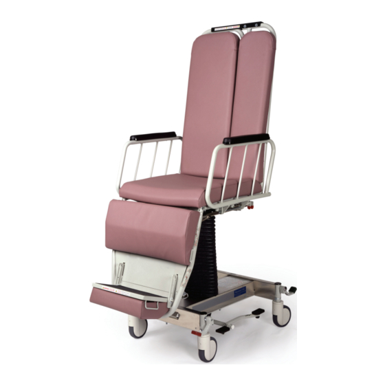
- Page 1 OPERATOR AND SERVICE MANUAL ® Hausted Video Imaging Chairs Model VIC329 & VIC429 (10/25/06) 066832...
- Page 2 If missing, contact STERIS for replacement copies, giving the serial number and model numbers of the unit. STERIS carries a complete line of accessories for use with this washer. A STERIS representative will gladly review these with you.
- Page 3 EC Authorized Representative STERIS Limited STERIS House Jays Close Viables Basingstoke Hampshire RG22 4AX UNITED KINGDOM Manufactured by: STERIS Corporation 2720 Gunter Park East Montgomery, AL 36109 • USA TEL: 334 277 6660 FAX: 334 271 5450 Equipment not suitable for use...
-
Page 4: Table Of Contents
TABLE OF CONTENTS Section Title Page 1 LISTING OF WARNINGS AND CAUTIONS ........1-1 2 UNPACKING INSTRUCTIONS ............2-1 3 OPERATING INSTRUCTIONS ............3-1 3.1 Braking and Steering ....................3-1 3.1.1 Applying the Brakes ..................... 3-1 3.1.2 Releasing the Brakes ................... 3-1 3.1.3 Applying the Steering Lock .................. -
Page 5: Listing Of Warnings And Cautions
LISTING OF WARNINGS AND CAUTIONS The following is a listing of the safety precautions which must be observed when operating and servicing this equipment. WARNINGS indicate the potential for danger to personnel, and CAUTIONS indicate the potential for damage to equipment. -
Page 6: Unpacking Instructions
5. If any of the features of the chair do not frequently incurred when work properly, call STERIS for service. bands are cut and tension Step 5 – Clean the chair using a mild detergent to remove any dirt accumu- released. -
Page 7: Operating Instructions
OPERATING INSTRUCTIONS 3.1 Braking and Steering W A R N I N G – P E R S O N A L INJURY HAZARD: Patient entry, egress and transfer from the VIC chair should always be from the center side rail location with the side rail in the down position and brakes locked. - Page 8 WARNINGS – PERSONAL INJURY HAZARD: A– T h e V I C c h a i r h a s a I– T h e p a t i e n t s h o u l d b e warning label on the back p l a c e d i n a f u l l y u p r i g h t o f t h e b a c k s e c t i o n s t a t -...
- Page 9 See WARNING – C & H See WARNING – A See WARNING – F See WARNING – I 22" 22" 50" 70.5" See WARNING – B, F, H & I See Section 3.2.3 See WARNING – F See Section 3.5 See WARNING –...
-
Page 10: Releasing The Steering Lock
3.1.4 Releasing the Depress the red pedal at either of the right side corners of the unit, until the pedal Steering Lock is in a horizontal position (Figure 3-2). All four wheels should rotate and swivel freely. 3.2 Top Adjustment W A R N I N G –... -
Page 11: Reclining The Chair Back
3.2.3 Reclining the Chair Squeeze the green recline lever on the right side of the back section (Figure Back 3-7). Push back on the back section until it is at desired position, (Figure 3-8) position can vary from upright to 10° trendelendurg positions. Note that chair has a degree indicator located on the lower back section on the right side of the chair. -
Page 12: Independent Leg Section
3.3 Independent Leg Section W A R N I N G – P E R S O N A L INJURY HAZARD: The VIC chair has a warning label on the top of the base cover that states: When chair is in the non-transport mode: Patient must remain fully upright;... -
Page 13: Adjustable Footrest
3.4 Adjustable Footrest W A R N I N G – P E R S O N A L INJURY HAZARD: The VIC chair has a warning label on the foot rest stating: Do not stand on foot rest. 3.4.1 Repositioning the The footrest has three positions;... -
Page 14: Hinging Rails
3.5 Hinging Rails W A R N I N G – P E R S O N A L INJURY HAZARD: Patient entry, egress and transfer from the VIC chair should always be from the center side rail location with the side rail in the down position and brakes locked. -
Page 15: Non-Transport Mode (Anterior/Posterior Position)
The transport mode is when the green arrows on the Transport Mode seat and back section are aligned, the back section is (Lateral Position) in the full upright position and the chair is in low height. Rear View Side View Non-Transport Mode NEVER –... -
Page 16: Transport Mode (Lateral Position)
3.6.2 Non-Transport Mode Lock the caster brakes (Figure 3-1). Secure patient in sitting position with (Anterior/Posterior restraints. Elevate chair to maximum height (Figure 3-4). Pull out on the seat Position) lock knob (Figure 3-22) to release lock. Rotate chair counterclockwise (Figure 3-23), until it locks into the non-transport mode (see Figure 3-21). -
Page 17: Patient Transfer Instructions
Definition of terms used in instructions below (see Figure 3-26). 3.7 Patient Transfer Transfer side: Instructions Secondary Patient Device – the transfer side will always be located on the attendants right hand side, when standing at the patient’s foot end of the W A R N I N G –... - Page 18 Figure 3-26 3-12 066832 Operator Manual Operating Instructions...
-
Page 19: Recommended Preventive Maintenance
RECOMMENDED PREVENTIVE MAINTENANCE Material Procedure Schedule Lubricating oil, light-duty Lubricate all moving and sliding parts 6 Months grease, wax stick lubricant. and hinge points. 1 2 3 4 5 6 7 8 9 0 1 2 3 4 5 6 7 8 9 0 1 2 3 4 5 6 7 8 9 0 1 2 1 2 3 4 5 6 7 8 9 0 1 2 3 4 5 6 7 8 9 0 1 2 3 4 5 6 7 8 9 0 1 2 1 2 3 4 5 6 7 8 9 0 1 2 3 4 5 6 7 8 9 0 1 2 3 4 5 6 7 8 9 0 1 2 1 2 3 4 5 6 7 8 9 0 1 2 3 4 5 6 7 8 9 0 1 2 3 4 5 6 7 8 9 0 1 2 1 2 3 4 5 6 7 8 1 2 3 4 5 6 7 8 9 0 1 2 3 4 5 6 7 8 9 0 1 2 3 4 5 6 7 8 9 0 1 2 1 2 3 4 5 6 7 8 9 0 1 2 3 4 5 6 7 8 9 0 1 2 3 4 5 6 7 8 9 0 1 2 1 2 3 4 5 6 7 8 9 0 1 2 3 4 5 6 7 8 9 0 1 2 3 4 5 6 7 8 9 0 1 2 1 2 3 4 5 6 7 8 9 0 1 2 3 4 5 6 7 8 9 0 1 2 3 4 5 6 7 8 9 0 1 2 1 2 3 4 5 6 7 8 1 2 3 4 5 6 7 8 9 0 1 2 3 4 5 6 7 8 9 0 1 2 3 4 5 6 7 8 9 0 1 2 1 2 3 4 5 6 7 8 9 0 1 2 3 4 5 6 7 8 9 0 1 2 3 4 5 6 7 8 9 0 1 2 1 2 3 4 5 6 7 8 9 0 1 2 3 4 5 6 7 8 9 0 1 2 3 4 5 6 7 8 9 0 1 2 1 2 3 4 5 6 7 8 9 0 1 2 3 4 5 6 7 8 9 0 1 2 3 4 5 6 7 8 9 0 1 2 1 2 3 4 5 6 7 8 1 2 3 4 5 6 7 8 9 0 1 2 3 4 5 6 7 8 9 0 1 2 3 4 5 6 7 8 9 0 1 2 1 2 3 4 5 6 7 8 9 0 1 2 3 4 5 6 7 8 9 0 1 2 3 4 5 6 7 8 9 0 1 2 1 2 3 4 5 6 7 8 9 0 1 2 3 4 5 6 7 8 9 0 1 2 3 4 5 6 7 8 9 0 1 2 1 2 3 4 5 6 7 8 9 0 1 2 3 4 5 6 7 8 9 0 1 2 3 4 5 6 7 8 9 0 1 2 1 2 3 4 5 6 7 8... -
Page 20: Optional Accessories
SA4002 VIC back extension field upgrade VIC429 only (mfg after 4/98) It is recommended that only STERIS approved accessories be used with this device. To order accessories or for more detailed information on accessories please contact STERIS Corporation at: 1-800-333-8828... -
Page 21: Recommended Replacement Parts
RECOMMENDED REPLACEMENT PARTS Recommended Replacement Parts Operator Manual 066832... - Page 22 63 64 18 62 63 64 Figure 6-1. VIC Base Assembly 066832 Operator Manual Recommended Replacement Parts...
- Page 23 FIG. & UNITS PER PART ITEM DESCRIPTION ASSEMBLY NUMBER 6-1- 066905 VIC BASE ASSEMBLY ............... 066898 ASSEMBLY, Base Frame VIC ............ P61117 ASSEMBLY, Outside Column ............. 031334 SCREW, Hex Head Cap, 5/16-18 x 2" Long ....... 031076 WASHER, 1/4 SAE Flat ............... 031057 NUT, Lock 5/16-18 ..............
- Page 24 FIG. & UNITS PER PART ITEM DESCRIPTION ASSEMBLY NUMBER 6-1- 066905 VIC BASE ASSEMBLY (CONTINUED) ........066867 ASSEMBLY, Inside Column ............066869 LABEL, Operation ................ 066868 LABEL, Seat Lock ................ 031080 WASHER, Flat, 5/16" ..............069192 HEAD, Steer Pedal ..............055119 WASHER, Nylon, 1/2"...
- Page 25 3 27 Figure 6-2. Seat Assembly 066832 Operator Manual Recommended Replacement Parts...
- Page 26 FIG. & UNITS PER PART ITEM DESCRIPTION ASSEMBLY NUMBER 6-2- SEAT ASSEMBLY ..............066864 ASSEMBLY, Seat Section ............031010 SCREW , Hex Head Cap, 5/16-18 x 3/4" Long ......066865 ASSEMBLY, Seat Plunger ............031057 NUT, Lock, 5/16-18 ..............066852 BLOCK, Pivot Support ..............
- Page 27 42 38 Figure 6-3. Foot Section 066832 Operator Manual Recommended Replacement Parts...
- Page 28 FIG. & UNITS PER PART ITEM DESCRIPTION ASSEMBLY NUMBER 6-3- FOOT SECTION ................068035 ASSEMBLY, Foot Section ............031036 SCREW, Phillips Oval Head, 5/16-24 x 15/16 Long ....061358 LABEL, Operating ................ 011318 PIN, Clevis, 3/8 x 1-7/16: Long ............ 030287 NUT, PAL, 3/8"...
- Page 29 FIG. & UNITS PER PART ITEM DESCRIPTION ASSEMBLY NUMBER 6-3- FOOT SECTION (CONTINUED) ..........031102 SCREW, Set, Knurled,1/4-20 x 1/4" Long ........066821 ASSEMBLY, Plunger Tube, Left ..........061328 ASSEMBLY, Plunger Rod ............061324 RING, Internal Retaining 3/8" ............066820 ASSEMBLY, Plunger Tube ............
- Page 30 Removable push handles – place in wells on back of back section. Kit Part Number SA0721 NOTE: For Model 429 VIC Chair, mount gas spring in this location. Figure 6-4. Back sections 6-12 066832 Operator Manual Recommended Replacement Parts...
- Page 31 FIG. & UNITS PER PART ITEM DESCRIPTION ASSEMBLY NUMBER 6-4- BACK SECTIONS, MODEL 329 ..........BACK SECTIONS, MODEL 429 ..........066884 ASSEMBLY, Back Section ............– 031036 SCREW, Phillips Oval Head, 5/16-24 x 15/16" Long ....061157 BOLT, Shoulder, 3/8 DIA. x 1.00" Long ........035115 WASHER, Nylon, 3/4 O.D.
- Page 32 FIG. & UNITS PER PART ITEM DESCRIPTION ASSEMBLY NUMBER 6-4- BACK SECTIONS, MODEL 329 (CONTINUED) ......BACK SECTIONS, MODEL 429 (CONTINUED) ......13104L PILE, Velcro, 2.00 x 5.00 (Not Shown) ........– 000794 Rivet, Pop, 3/16 (Not Shown) ............– 075298 Label, VIC Back Instruction ............
Need help?
Do you have a question about the Hausted VIC329 and is the answer not in the manual?
Questions and answers