
Subscribe to Our Youtube Channel
Related Manuals for Steris Hausted MBC


Summary of Contents for Steris Hausted MBC
- Page 1 OPERATOR AND SERVICE MANUAL ® ® Hausted Mammography/Biopsy Chair (11/20/06) 066984...
- Page 2 If missing, contact STERIS for replacement copies, giving the serial number and model numbers of the unit. STERIS carries a complete line of accessories for use with this stretcher. A STERIS representative will gladly review these with you.
- Page 3 Montgomery, Alabama is an ISO 13485 certified facility. The base language of this document is ENGLISH. Any translations must be made from the base language document. STERIS Offices Worldwide Canada 800 661 3937 Germany 49 22 33 69990 Hong Kong...
-
Page 4: Table Of Contents
TABLE OF CONTENTS Section Title Page 1 LISTING OF WARNINGS AND CAUTIONS ........1-1 2 UNPACKING INSTRUCTIONS ............2-1 3 OPERATING INSTRUCTIONS ............3-1 3.1 Braking And Steering Operation .................. 3-3 3.1.1 Applying The Brakes .................... 3-3 3.1.2 Releasing The Brake ..................... 3-3 3.1.3 Applying The Steer Lock .................. -
Page 5: Listing Of Warnings And Cautions
LISTING OF WARNINGS AND CAUTIONS The following is a listing of the safety precautions which must be observed when operating and servicing this equipment. WARNINGS indicate the potential for danger to personnel, and CAUTIONS indicate the potential for damage to equipment. -
Page 6: Unpacking Instructions
5. If any of the features of the Horizon frequently incurred when Stretcher do not work properly, call STERIS for service. bands are cut and tension Step 5 – Clean the MBC Chair using a mild detergent to remove any dirt released. -
Page 7: Operating Instructions
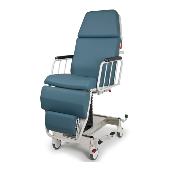
STERIS offers a complete product line for your specialty needs. STERIS’s MBC has a Warning Label located at the head and foot ends of the WARNING – PERSONAL chair’s frame, stating: Do not sit on end: Tipping may occur . - Page 8 The chair specifications are: hydraulic height adjustment, pneumatic backrest adjustment, including 10° trendelenburg, and a four wheel lock caster braking system with steering lock. WARNIN G – PERSONAL INJURY HAZARD: When the unit is in the stretcher posi- tion, DO NOT sit on the head or foot end of the patient surface.
-
Page 9: Braking And Steering Operation
3.1 Braking And Steering Operation 3.1.1 Applying The Brakes The four wheel central braking system is activated by depressing the RED pedal, (to approximately 45° at any corner of the unit. This locks all four of the caster wheels from rotating and swivelling. (See Figure 3-3.) Depress the GREEN pedal at any corner of the unit to a horizontal position. -
Page 10: Height & Top Adjustment
3.2 Height & Top Adjustment 3.2.1 Height Adjustment To elevate the unit, pump the UP pedal, using smooth full strokes to insure patient comfort. (See Figure 3-5.) NOTE: Pedals are located on both sides of the unit. When the unit reaches the desired height, stop the pumping action. NOTE: Do not stand on the pedal. -
Page 11: Top Adjustment
Figure 3-6 3.2.3 Top Adjustment To adjust the unit anywhere from the chair position to the stretcher position grasp the RECLINE handle, (A), and adjust the unit to the desired position and release the handle. (See Figure 3-7.) To adjust the unit into the trendelenburg position the unit must be in the CHAIR 3.2.4 Trendelenburg position. -
Page 12: P.r./Surgical Leg Installation & Operation
C.P.R./SURGICAL LEG INSTALLATION & OPERATION Tools needed: regular screwdriver, 5/32" Allen wrench, 7/16" socket wrench. 4.1 C.P.R./Surgical Step 1: Remove the 4 screws used to mount the A.P.C. Push Bar. Support Leg Step 2: Mount Item 1 (C.P.R. Leg Assembly) to the A.P.C. on the left and the (Accessory Number right side of the chair, on the inside of the Push Bar Ears as shown, using APC025) -
Page 13: Operating Instructions
4.1.2 Operating C.P.R. Use - Instructions (Figure 4-3) Step 1: Pull the Velcro away from the tubes. Step 2: Adjust the MBC to the desired horizontal position. The legs will automatically hinge into position and lock. Step 3: Pull the knob out and allow the rack to slide until it makes contact with the floor. -
Page 14: Recommended Preventive Maintenance
NOTE: If units are pressure washed or steam cleaned, lubrication of all hinging, moving, and sliding points should be done afterwards. (Pressure washing and steam cleaning are not recommended procedures and can void warranty.) For more details information, please contact: STERIS Corporation at: 1-800-333-8828 Recommended Preventive Maintenance... -
Page 15: Optional Accessories
OPTIONAL ACCESSORIES Part Number Description APC012-00 Restraint Straps APC14D-00 Oxygen Tank Holder 000018-00 Telescoping I.V.Rod APC020-00 Patient Tray APC025-00 Surgical Support Legs (Recommended Accessory) APC026-00 Stirrups 061239-00 Armboard with 1" Pad (Reclined Position) 065990-00 Armboard with 1" Pad (Seated Position) SA0671-00 Dorsocervical Pillow (Qty. -
Page 16: Recommended Replacement Parts
RECOMMENDED REPLACEMENT PARTS Recommended Replacement Parts Operator Manual 066984... - Page 17 Figure 7-1. MBC Final Assembly 066984 Operator Manual Recommended Replacement Parts...
- Page 18 FIG. & UNITS PER PART ITEM DESCRIPTION ASSEMBLY NUMBER 7-1- MBC FINAL ASSEMBLY ............066840 ASSEMBLY, MBC Base .............. 031012 SCREW, Hex Head Cap, 0.313-18 x 1.00" Long ......068058 PAD, Rail ..................062128 SCREW, Button Socket Head Cap, 0.250-20 x 1.250" Long ..031057 NUT, Lock, 0.313-18 ..............
- Page 19 Figure 7-2. MBC Top Assembly 066984 Operator Manual Recommended Replacement Parts...
- Page 20 FIG. & UNITS PER PART ITEM DESCRIPTION ASSEMBLY NUMBER 7-2- MBC TOP ASSEMBLY ..............068039 WELDMENT, Seat Section ............061011 WELDMENT, MBC Back Section ..........068030 WELDMENT, Leg Frame ............. 031036 SCREW, Phillips Oval Head, 0.313-24 x 0.938" Long ....067288 WELDMENT, Connecting Link ............
- Page 21 Figure 7-3. MBC Back Section Assembly 066984 Operator Manual Recommended Replacement Parts...
- Page 22 FIG. & UNITS PER PART ITEM DESCRIPTION ASSEMBLY NUMBER 7-3- MBC BACK SECTION ASSEMBLY ........... 061073 WELDMENT, Trendelenburg Handle, Right ....... 061089 NYLINER, Thompson, Flange ............. 061042 ANGLE, Handle Support ............. 061084 CONNECTOR, Handle ..............031111 PIN, Spring, 0.125" x 0.625" Long ..........061076 WELDMENT, Trendelenburg Handle, Left ........
- Page 23 Figure 7-4. MBC Base Assembly 066984 Operator Manual Recommended Replacement Parts...
- Page 24 FIG. & UNITS PER PART ITEM DESCRIPTION ASSEMBLY NUMBER 7-4- MBC BASE ASSEMBLY ............. 066898 WELDMENT, MBC Base Frame ..........068028 ASSEMBLY, Column ..............031334 SCREW, Hex Head Cap, 0.313-18 x 2.000" Long ...... 031076 WASHER, Flat, 0.313" ..............031057 NUT, Lock, 0.313-18 ..............
- Page 25 Figure 7-5. MBC Base Assembly 7-10 066984 Operator Manual Recommended Replacement Parts...
- Page 26 FIG. & UNITS PER PART ITEM DESCRIPTION ASSEMBLY NUMBER 7-5- MBC BASE ASSEMBLY ............. Not Used 066900 ASSEMBLY, End Cover .............. 061261 BELLOWS, MBC ................066844 CLIP, Bellows ................000849 TIE, Cable ..................075855 LABEL, MBC Chair ..............075843 LABEL, Product ................Not Used P61379 ASSEMBLY, Bellows Mounting Angle ........
- Page 27 After assembly, Item 6 is to be centered within Item 3, tighten Item 5 down until Item 6 is held firmly in place. Install Item 7, but do not tighten down. NOTE: Apply No.2 Moly Grease to Item 4 before assembly. Item Numbers are listed in order of assembly.
- Page 28 FIG. & UNITS PER PART ITEM DESCRIPTION ASSEMBLY NUMBER 7-6- COLUMN AND PUMP ASSEMBLY ..........P61121 HANGER, Hydraulic Jack Support ..........061122 MEDIJACK ................... P61117 WELDMENT, Square Outside Column ........066178 SUPPORT, Short Glide ..............061116 SCREW, Column Guide w/Point ..........068048 WELDMENT, Inside Column ............
Need help?
Do you have a question about the Hausted MBC and is the answer not in the manual?
Questions and answers