
Related Manuals for Pilz PSS u2 ES 4AO U/I


Summary of Contents for Pilz PSS u2 ES 4AO U/I
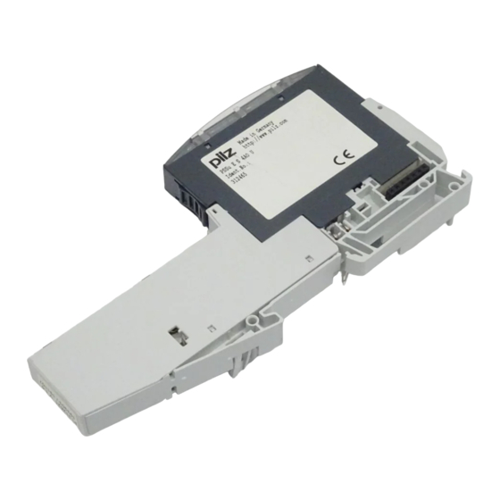
- Page 1 PSS u2 ES 4AO U/I Control system PSS u2 Remote I/O system PSS u2 Operating Manual-1005178-EN-03...
- Page 2 We do assure you that all persons are regarded without discrim- ination and on an equal basis. All rights to this documentation are reserved by Pilz GmbH & Co. KG. Copies may be made for the user's internal purposes. Suggestions and comments for improving this documenta- tion will be gratefully received.
-
Page 3: Table Of Contents
Changing an electronic module during operation ..............Wiring ............................General wiring guidelines ......................Terminal configuration ......................Operation ..........................Display elements and messages ....................Technical details ........................Order reference ........................10.1 Product ............................. 10.2 Accessories ..........................Operating Manual PSS u2 ES 4AO U/I 1005178-EN-03... -
Page 4: Introduction
This operating manual explains the function and operation, describes the installation and provides guidelines on how to connect the product. This documentation is valid for the product PSS u2 ES 4AO U/I hardware version 01 or higher. It is valid until new documentation is published. - Page 5 Introduction INFORMATION This gives advice on applications and provides information on special fea- tures. Operating Manual PSS u2 ES 4AO U/I 1005178-EN-03...
-
Page 6: Overview
Details of the terminal blocks that can be used are available under "Intended Use". Module features Application of the product PSS u2 ES 4AO U/I: Electronic module with analogue outputs for standard applications 4 analogue voltage and current outputs... -
Page 7: Safety
Use of the module outside the areas described in this manual, Any use of the module that is not in accordance with the technical details. The module PSS u2 ES 4AO U/I may be used in conjunction with the following terminal block:... -
Page 8: Safety Regulations
Any type of modification has been made (e.g. exchanging components on the PCB boards, soldering work etc.). 3.3.3 Disposal When decommissioning, please comply with local regulations regarding the disposal of electronic devices (e.g. Electrical and Electronic Equipment Act). Operating Manual PSS u2 ES 4AO U/I 1005178-EN-03... -
Page 9: Function Description
Supply +24 V DC Output Output n.c. Fig.: Block diagram PSS u2 ES 4AO U/I Supply The module is supplied with voltage via the head module. The periphery supply is used to supply the outputs. Current and voltage range The output signals for each output are transmitted to the output module via the ST module bus. -
Page 10: Representation Of The Analogue Value
-12 mA 16384 0100 0000 0000 0000 4000 -18 mA 8192 0010 0000 0000 0000 2000 -21.5998 mA 3277 0000 1100 1100 1101 0CCD -23.7597 mA 0000 0001 0100 1000 0148 Operating Manual PSS u2 ES 4AO U/I | 10 1005178-EN-03... - Page 11 0000 0000 0000 1000 0008 610.36 µV 0000 0000 0000 0100 0004 305.18 µV 0000 0000 0000 0010 0002 152.59 µV 0000 0000 0000 0001 0001 0000 0000 0000 0000 0000 Operating Manual PSS u2 ES 4AO U/I | 11 1005178-EN-03...
- Page 12 = 24V * O-PI / 65535 - 12V O-PI: Digital value in the process image of outputs in decimal representation Note: The digital value in decimal representation can assume values between 0 … 65 535. Operating Manual PSS u2 ES 4AO U/I | 12 1005178-EN-03...
-
Page 13: Reaction Times
Switching off the LEDs The LEDs have two energy-saving levels: – Switching off the LEDs that display the terminal status – Switching off the LEDs that display the module and terminal status Operating Manual PSS u2 ES 4AO U/I | 13 1005178-EN-03... -
Page 14: Structure Of The Process Image
Valid bit of output O1 to the output signal Bit 2 Valid bit of output O2 Bit 3 Valid bit of output O3 Bit 4 … 7 None Constant "0" Operating Manual PSS u2 ES 4AO U/I | 14 1005178-EN-03... -
Page 15: Installation
6.1.1 Dimensions The dimensions include the backplane, electronic module and terminal block. 12,5 51,1 111,1 Fig.: Dimensions in mm, including backplane, electronic module and terminal block Operating Manual PSS u2 ES 4AO U/I | 15 1005178-EN-03... -
Page 16: Inserting And Removing An Electronic Module
Inserting an electronic module 1. Insert the electronic module into the suspen- sion lug on the back- plane. 2. Swivel the electronic module downwards until you hear it click into place. Operating Manual PSS u2 ES 4AO U/I | 16 1005178-EN-03... - Page 17 Installation 3. Insert the terminal block into the suspen- sion lug on the module. 4. Swivel the terminal block upwards until you hear it click into place. Operating Manual PSS u2 ES 4AO U/I | 17 1005178-EN-03...
-
Page 18: Removing An Electronic Module
2. Press the unlocking mechanism that is shown by the arrow and pull off the electronic module upwards. Operating Manual PSS u2 ES 4AO U/I | 18 1005178-EN-03... -
Page 19: Changing An Electronic Module During Operation
– Restart of the head module. After a restart, the system behaves as after a warm reset using a reset pushbutton (see operating manual of the head module, chapter “Reset pusbutton", section "Carrying out a warm reset (restart)"). Operating Manual PSS u2 ES 4AO U/I | 19 1005178-EN-03... -
Page 20: Wiring
9: O2 current/voltage output 10: 0V ground analogue output 11: P0 shield connection 12: Not assigned 13: O3 current/voltage output 14: 0V ground analogue output 15: P0 shield connection 16: Not assigned Operating Manual PSS u2 ES 4AO U/I | 20 1005178-EN-03... -
Page 21: Operation
Display elements and messages Only the terminals 1, 5, 9 and 13 are active. Legend [1] Module status display [2] Terminal status display Legend LED on LED flashes LED flashes briefly LED off Operating Manual PSS u2 ES 4AO U/I | 21 1005178-EN-03... - Page 22 Temperature warning: Too warm (1) See module's diagnostic log The module status display and all See module's terminal status displays flash syn- diagnostic log chronously Periphery supply is missing/temper- ature error: Too hot (1)/EMC error Operating Manual PSS u2 ES 4AO U/I | 22 1005178-EN-03...
-
Page 23: Technical Details
Ambient temperature In accordance with the standard EN 60068-2-14 Temperature range 0 - 60 °C Storage temperature In accordance with the standard EN 60068-2-1/-2 Temperature range -40 - 70 °C Operating Manual PSS u2 ES 4AO U/I | 23 1005178-EN-03... - Page 24 Mechanical data Material Housing Mounting type plug-in Dimensions Height 110,8 mm Width 12,5 mm Depth 72,5 mm Weight 40 g Where standards are undated, the 2015-08 latest editions shall apply. Operating Manual PSS u2 ES 4AO U/I | 24 1005178-EN-03...
-
Page 25: Order Reference
61 x 11.5 mm, scope of supply: 10 pieces Coding elements Product type Features Order no. PSS u2 A CE E Coding elements for electronic modules, 328860 (10 pcs.) scope of supply: 10 pieces Operating Manual PSS u2 ES 4AO U/I | 25 1005178-EN-03... - Page 26 PSS u2 B 4 Backplane, 4 slots 328810 Product type Features Order No. PSS u2 A SH 4 Shield connection element for backplane 328820 (10 pcs.) with 4 slots, scope of delivery: 10 pieces Operating Manual PSS u2 ES 4AO U/I | 26 1005178-EN-03...
- Page 27 We are represented internationally. Please refer to our homepage www.pilz.com for further details or contact our headquarters. Headquarters: Pilz GmbH & Co. KG, Felix-Wankel-Straße 2, 73760 Ostfildern, Germany Telephone: +49 711 3409-0, Telefax: +49 711 3409-133, E-Mail: info@pilz.com, Internet: www.pilz.com...
Need help?
Do you have a question about the PSS u2 ES 4AO U/I and is the answer not in the manual?
Questions and answers