Table of Contents
Advertisement
Quick Links
Advertisement
Table of Contents

Related Manuals for Pilz PDP67 F 4 code


Summary of Contents for Pilz PDP67 F 4 code
- Page 1 PDP67 F 4 code Decentralised periphery Operating Manual 1001531-EN-06...
- Page 2 Preface This document is a translation of the original document. All rights to this documentation are reserved by Pilz GmbH & Co. KG. Copies may be made for internal purposes. Suggestions and comments for improving this documentation will be gratefully received.
-
Page 3: Table Of Contents
Examples of independent circuit 7.1.2 Series connection of modules 7.1.2.1 Examples of series connection 7.1.2.2 Voltage drop Section 8 Operation Messages 8.1.1 Display elements for device diagnostics Section 9 Technical details Section 10 Order reference Operating Manual PDP67 F 4 code 1001531-EN-06... - Page 4 Contents 10.1 Order reference for module 10.2 Order reference for accessories Section 11 EC declaration of conformity Operating Manual PDP67 F 4 code 1001531-EN-06...
-
Page 5: Introduction
Introduction Introduction Validity of documentation This documentation is valid for the products PDP67 F 4 code, PDP67 F 4 code VA. It is valid until new documentation is published. This operating manual explains the function and operation, describes the installation and provides guidelines on how to connect the product. - Page 6 It also highlights areas within the text that are of particular import- ance. INFORMATION This gives advice on applications and provides information on special fea- tures. Operating Manual PDP67 F 4 code 1001531-EN-06...
-
Page 7: Overview
Application of the products PDP67 F 4 code, PDP67 F 4 code VA: Decentralised passive distributor for use in rugged industrial environments up to protection type IP67 for connecting PSENcode, PSENslock and PSENini sensors to a Pilz control sys- tem. The product has the following features:... -
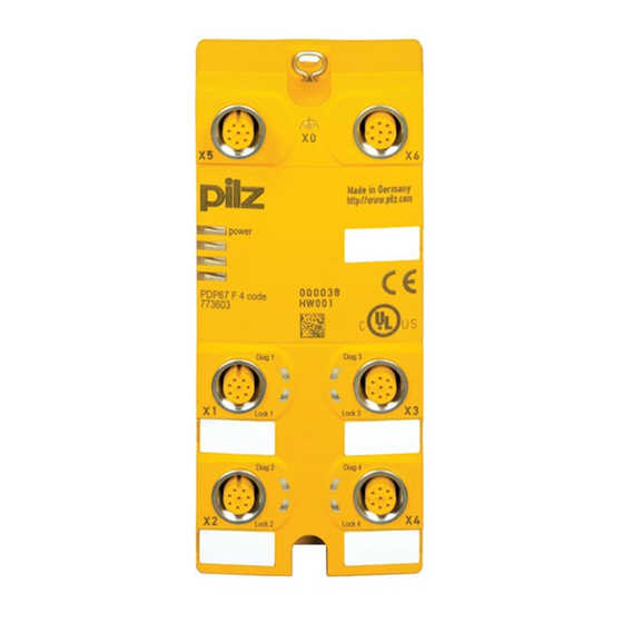
Page 8: Front View
Female connectors for connecting to the evaluation device (for connecting the sensors to X1 ... X4) Female connectors for connecting signal outputs (Diag) and inputs for control com- mands for magnetic guard locking (Lock) LEDs: – Power – Diag – Lock Operating Manual PDP67 F 4 code 1001531-EN-06... -
Page 9: Safety
Safety Intended use Decentralised passive distributor for use in rugged industrial environments up to protection type IP67 for connecting PSENcode, PSENslock and PSENini sensors to a Pilz control sys- tem. The following is deemed improper use in particular: Any component, technical or electrical modification to the product Use of the product outside the areas described in this manual Use of the product outside the technical details (see Technical details). -
Page 10: Disposal
Any type of modification has been made (e.g. exchanging components on the PCB boards, soldering work etc.). 3.2.3 Disposal When decommissioning, please comply with local regulations regarding the disposal of electronic devices (e.g. Electrical and Electronic Equipment Act). Operating Manual PDP67 F 4 code 1001531-EN-06... -
Page 11: Function Description Operation
Function description Function description Operation Using the module PDP67 F 4 code/PDP67 F 4 code VA, up to four PSENcode, PSENslock and/or PSENini sensors can be connected in series and connected to an evaluation device. 4.1.1 Internal wiring diagram 6 I1... -
Page 12: Installation
Unused connectors should be sealed using blind plugs. To install the system, proceed as follows: Fit 2 x M4 internal threads on the mounting surface. Use two fixing screws to attach the product to the mounting plate. 5.1.1 Dimensions Operating Manual PDP67 F 4 code 1001531-EN-06... -
Page 13: Wiring
You can use prefabricated sensor cables from Pilz for connecting the sensors. CAUTION! In order to guarantee protection type IP67, unused plug-in connectors should be sealed using the blind plugs supplied. - Page 14 6: Input lock 2 (for control command for magnetic guard locking) 7: Input lock 3 (for control command for magnetic guard locking) 8: Input lock 4 (for control command for magnetic guard locking) Operating Manual PDP67 F 4 code 1001531-EN-06...
-
Page 15: Preparing For Operation
Always connect the evaluation device to the last free female connector. NOTICE When commissioning, activate the safety function of each sensor in the safety chain and check the correct response of the evaluation device's safety outputs. Operating Manual PDP67 F 4 code 1001531-EN-06... -
Page 16: Examples Of Independent Circuit
Preparing for operation 7.1.1.1 Examples of independent circuit Connection example 1: Connection of four sensors (X1 ... X4) Auswertegerät/ Evaluation device ST: Standard FS: Fail-Safe PSEN PSEN PSEN PSEN *Adapter: PDP67 Connector cs/PDP67 Connector cs VA Operating Manual PDP67 F 4 code 1001531-EN-06... -
Page 17: Series Connection Of Modules
If the evaluation device is connected to a female connector before or between the sensors, all sensors connected thereafter will not be evaluated. Serious injury or death may result, depending on the application. Always connect the evaluation device to the last free female connector. Operating Manual PDP67 F 4 code 1001531-EN-06... -
Page 18: Examples Of Series Connection
Examples of series connection Connection example 1: Series connection when connecting four sensors (X1 ... X4) on the first module ST: Standard Evaluation device FS: Fail-Safe PSEN PSEN PSEN PSEN PSEN PSEN PSEN PSEN PSEN PSEN *Adapter: PDP67 Connector cs/PDP67 Connector cs VA Operating Manual PDP67 F 4 code 1001531-EN-06... -
Page 19: Voltage Drop
To increase the max. cable length, the input voltage can be permanently increased by the voltage tolerance (see Technical Details). Calculation example: The 0.25 mm² sensor cable is used. Voltage drop per 10 m and per 100 mA: 0.15 V Operating Manual PDP67 F 4 code 1001531-EN-06... - Page 20 Voltage drop per 10 m and per 100 mA PSS SB BUSCABLE LC 0.1 V Sensor cable 0.25 mm 0.15 V Sensor cable 0.34 mm 0.11 V Sensor cable 0.5 mm 0.07 V Operating Manual PDP67 F 4 code 1001531-EN-06...
-
Page 21: Operation
The actuator is within the response range The actuator is not within the response range Lock gree Control command for magnetic guard locking available Control command for magnetic guard locking not available Operating Manual PDP67 F 4 code 1001531-EN-06... -
Page 22: Technical Details
In accordance with the standard EN 60664-1 EN 60664-1 Overvoltage category Pollution degree Protection type Housing IP67 IP67 Terminals IP67 IP67 Mechanical data 773603 773613 Material Stainless steel 1.4305 Connection type Mounting type screw interlocked screw interlocked Operating Manual PDP67 F 4 code 1001531-EN-06... - Page 23 Technical details Mechanical data 773603 773613 Dimensions Height 120 mm 120 mm Width 60 mm 60 mm Depth 20 mm 20 mm Weight 240 g 240 g Operating Manual PDP67 F 4 code 1001531-EN-06...
-
Page 24: Order Reference
540 340 M12-8sm PSEN cable M12-8sf 540 341 M12-8sm PSEN cable M12-8sf 10 m 540 342 M12-8sm PSEN cable M12-8sf 20 m 540 343 M12-8sm PSEN cable M12-8sf 30 m 540 344 M12-8sm Operating Manual PDP67 F 4 code 1001531-EN-06... - Page 25 EC declaration of conformity This/(These) product(s) fulfil the requirements of the low voltage directive 2006/95/EG. The complete EC Declaration of Conformity is available on the Internet at www.pilz.com/down- loads. Representative: Norbert Fröhlich, Pilz GmbH & Co. KG, Felix-Wankel-Str. 2, 73760 Ost-...
- Page 26 Front cover Support Technical support is available from Pilz round the clock. Americas Australia Scandinavia Brazil +61 3 95446300 +45 74436332 +55 11 97569-2804 Spain Canada Europe +34 938497433 +1 888-315-PILZ (315-7459) Austria Switzerland +41 62 88979-30 Mexico +43 1 7986263-0...
Need help?
Do you have a question about the PDP67 F 4 code and is the answer not in the manual?
Questions and answers