
Subscribe to Our Youtube Channel
Related Manuals for Pilz PSSu E PD1-T


Summary of Contents for Pilz PSSu E PD1-T
- Page 1 PSSu E PD1(-T) Decentralised system PSSuniversal I/O Operating Manual 21453-EN-04...
- Page 2 Preface This document is a translation of the original document. All rights to this documentation are reserved by Pilz GmbH & Co. KG. Copies may be made for internal purposes. Suggestions and comments for improving this documentation will be gratefully received.
-
Page 3: Table Of Contents
Contents Section 1 Introduction Validity of documentation 1.1.1 Retaining the documentation Definition of symbols Section 2 Overview Module structure Module features Front view Section 3 Safety Intended Use Safety regulations 3.2.1 Use of qualified personnel 3.2.2 Warranty and liability 3.2.3 Disposal Section 4 Function description... -
Page 4: Operating Manual Pssu E Pd1(-T)
Introduction Introduction Validity of documentation This documentation is valid for the products PSSu E PD1 and PSSu E PD1-T. It is valid un- til new documentation is published. This operating manual explains the function and operation, describes the installation and provides guidelines on how to connect the product. - Page 5 Introduction INFORMATION This gives advice on applications and provides information on special fea- tures. Operating Manual PSSu E PD1(-T) 21453-EN-04...
-
Page 6: Overview
Module features The product has the following features: The module provides connections for external supplies. The external supplies are galvanically isolated from the module bus supplies. T-type: PSSu E PD1-T: for increased environmental requirements Operating Manual PSSu E PD1(-T) 21453-EN-04... -
Page 7: Front View
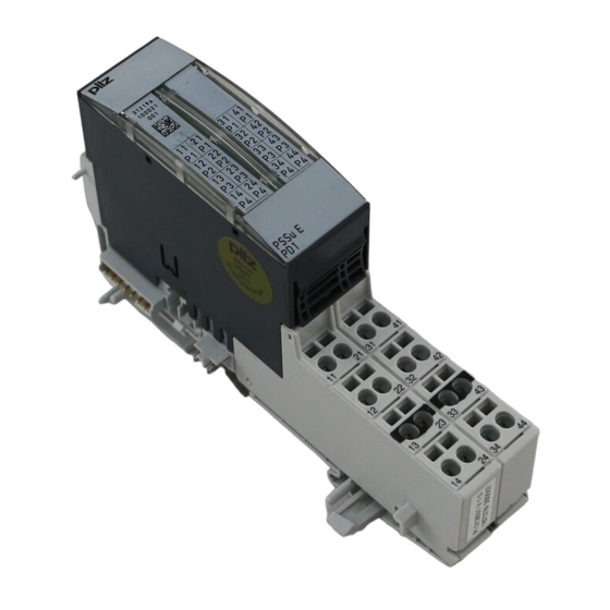
Overview Front view PSSu E 312196 000000 PSSu E Legend: A: Electronic module B: Base module 1: Labelling strip with: – Name of electronic module – Order number – Serial number – Hardware version number – 2D code 2: Labelling strip for the terminal configuration on the base module 3: Name of electronic module 4: Connection level 1 5: Connection level 2... - Page 8 Overview 8: Square mounting holes (connection levels 1, 2, 3 and 4) – With screw to loosen/tighten the screw terminal on base modules with screw termin- – With mechanism to operate the cage clamp on base modules with cage clamp ter- minals 9: Round connection holes (connection levels 1, 2, 3 and 4) for connecting the signal lines...
-
Page 9: Safety
The module may be used to feed and extract external supplies to and from the connection terminals. The module PSSu E PD1-T is suitable for use where there are increased environmental re- quirements (see Technical Details). Intended use includes making the electrical installation EMC-compliant. Please refer to the guidelines stated in the "PSSuniversal Installation Manual". -
Page 10: Warranty And Liability
Safety A competent person is someone who, because of their training, experience and current pro- fessional activity, has the specialist knowledge required to test, assess and operate the work equipment, devices, systems, plant and machinery in accordance with the general standards and guidelines for safety technology. -
Page 11: Function Description
Function description Function description Block diagram 11 21 31 41 12 22 32 42 14 24 34 44 (C-Rail) 13 23 33 43 Module features 4.2.1 Functions Module supply The module needs no supply from the module supply. Periphery supply The module distributes the periphery supply on the module bus. -
Page 12: Installation
Installation Installation General installation guidelines Please refer also to the PSSuniversal Installation Manual. NOTICE Damage due to electrostatic discharge! Electrostatic discharge can damage components. Ensure against discharge before touching the product, e.g. by touching an earthed, conductive sur- face or by wearing an earthed armband. 5.1.1 Dimensions 25,2 mm... -
Page 13: Installing The Base Module
Installation Installing the base module Prerequisite: The head module must be installed. If the head module does not have an integrated power supply, a supply voltage module must be installed to the right of the head module. Please note: For mechanical reasons it is not possible to mix base modules with screw terminals and base modules with cage clamp terminals. -
Page 14: Inserting And Removing An Electronic Module
Installation Inserting and removing an electronic module Please note: Only insert on to base modules that are already installed. Preferably these base modules should be ready wired. Electronic modules with outputs may only be inserted and removed when the load is switched off. -
Page 15: Inserting An Electronic Module
Installation 5.3.1 Inserting an electronic module Procedure: The electronic module must audibly lock into position [1]. Mark the electronic module using the labelling strips [2]. Schematic representation: Operating Manual PSSu E PD1(-T) 21453-EN-04... -
Page 16: Removing An Electronic Module
Installation 5.3.2 Removing an electronic module Procedure: Press the locking mechanisms [1] together simultaneously. Pull out the electronic module [2]. Schematic representation: 5.3.3 Changing an electronic module during operation It is possible to change an electronic module during operation. The configuration data is re- tained when a module is changed. -
Page 17: Wiring
Wiring Wiring General wiring guidelines Please note: Safe electrical isolation must be ensured for the external supplies. Failure to do so could result in electric shock. The external power supplies must comply with the current applicable standard EN 60950-1, EN 61140, EN 50178 or EN 61558-1. The maximum current load on the connection terminals is 4 A per supply. - Page 18 Wiring Base module with cage clamp terminals: – Insert the screwdriver [4] into the square hole [1]. – Insert the stripped cable into the round fixing hole [2], as far as it will go [5]. – Pull out the screwdriver [6]. –...
-
Page 19: Terminal Configuration
Wiring On base modules with screw terminals: – If you use a multi-strand cable to connect the I/Os, it is recommended that you use ferrules conforming to Parts 1 and 2 of DIN 46228, 0.14 ... 1.5 mm , Form A or C, although this is not essential. -
Page 20: Operation
Operation Operation Messages and display elements The module provides no diagnostic data and has no display elements. Operating Manual PSSu E PD1(-T) 21453-EN-04... -
Page 21: Technical Details
Technical details Technical details General 312196 314196 Approvals CE, cULus Listed BG, CE, TÜV, cULus Listed Application range Standard Standard Application in system environment From FS firmware version, other head modules From ST firmware version, other head modules From FS firmware version PSSu H F PN From ST firmware version PSSu H S PN... - Page 22 Technical details Environmental data 312196 314196 Shock stress In accordance with the standard EN 60068-2-27 EN 60068-2-27 Number of shocks Acceleration 11 ms 11 ms Duration In accordance with the standard EN 60068-2-27 EN 60068-2-27 1000 1000 Number of shocks Acceleration Duration 16 ms...
-
Page 23: Order Reference
Order reference Order reference Product Product type Features Order No. PSSu E PD1 Electronic module, base type 312 196 PSSu E PD1-T Electronic module, T-type 314 196 Accessories Base modules Product type Features Order no. PSSu BP 2/16 S Base module without C-rail with screw terminals... - Page 24 Front cover Support Technical support is available from Pilz round the clock. Americas Australia Scandinavia Brazil +61 3 95446300 +45 74436332 +55 11 97569-2804 Spain Canada Europe +34 938497433 +1 888-315-PILZ (315-7459) Austria Switzerland +41 62 88979-30 Mexico +43 1 7986263-0...
Need help?
Do you have a question about the PSSu E PD1-T and is the answer not in the manual?
Questions and answers