
Related Manuals for Pilz PSSu H PLC2 FS SN SD-T


Summary of Contents for Pilz PSSu H PLC2 FS SN SD-T
- Page 1 PSSu H PLC2 FS SN SD(-T) Operating Manual-1005195-EN-08 - Control system PSSuniversal PLC...
- Page 2 We do assure you that all persons are regarded without discrim- ination and on an equal basis. All rights to this documentation are reserved by Pilz GmbH & Co. KG. Copies may be made for the user's internal purposes. Suggestions and comments for improving this documenta- tion will be gratefully received.
-
Page 3: Table Of Contents
Contents Introduction ..........................5 Validity of documentation ......................5 1.1.1 Retaining the documentation ....................5 Definition of symbols .........................5 Third-party manufacturer licence information................6 Overview ..........................7 Module features ........................7 Front view..........................8 Safety ............................9 Intended use ..........................9 Safety regulations ........................10 3.2.1 Safety assessment........................10 3.2.2 Use of qualified personnel......................10 3.2.3 Warranty and liability.........................10 3.2.4... - Page 4 Contents 8.2.3 ST RUN.............................27 8.2.4 FS RUN.............................28 8.2.5 DIAG ............................29 8.2.6 ST FORCE ..........................30 8.2.7 FS FORCE ..........................31 8.2.8 MS.............................32 8.2.9 NS/BF............................33 8.2.10 ST SNp............................34 8.2.11 FS SNp............................35 8.2.12 5V, 24V .............................36 8.2.13 X3: LNK, X3: TRF, X4: LNK, X4: TRF..................37 Technical Details ........................38 Safety characteristic data......................42 Supplementary data .......................43...
-
Page 5: Introduction
Introduction Introduction Validity of documentation This operating manual explains the function and operation, describes the installation and provides guidelines on how to connect the product. The documentation is valid for the product types: PSSu H PLC2 FS SN SD from Version HW 2.0, FW 1.26.0 PSSu H PLC2 FS SN SD–T from Version HW 2.0, FW 1.26.0 It is valid until new documentation is published. -
Page 6: Third-Party Manufacturer Licence Information
Third-party manufacturer licence information This product includes Open Source software with various licenses. Further information is available in the document „Third-party manufacturer licence informa- tion PSS 4000-exclusive devices“ (document number 1003883) at www.pilz.com. Operating Manual PSSu H PLC2 FS SN SD(-T) 1005195-EN-08... -
Page 7: Overview
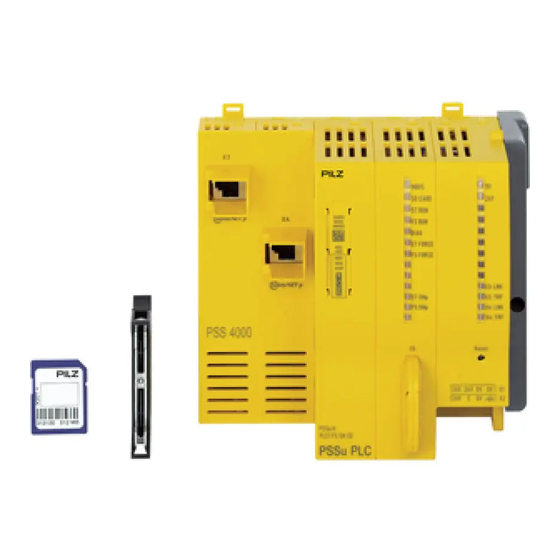
Overview Overview Module features The head module belongs to the performance class "Control system PSSu PLC". It can be used to connect a PSSu system to SafetyNET p or for non-safety-related applications it can be incorporated into a PROFINET project as an IO device. The head module has the following features: 2 free switch ports for connection to SafetyNET p External connections:... -
Page 8: Front View
Overview Front view NS/BF The labelling strip contains the following information: Order number Serial number Hardware version 2D code: Product information MAC address 2D code: MAC address Operating Manual PSSu H PLC2 FS SN SD(-T) 1005195-EN-08... -
Page 9: Safety
Please note that only head modules with a "BF"-LED are used with PROFINET IO. Particular application areas Increased environmental requirements The module PSSu H PLC2 FS SN SD-T is suitable for use where there are increased en- vironmental requirements (see Technical details [ 38]). -
Page 10: Safety Regulations
Safety Safety regulations 3.2.1 Safety assessment Before using a device, a safety assessment in accordance with the Machinery Directive is required. The product as an individual component fulfils the functional safety requirements in accord- ance with EN ISO 13849 and EN IEC 62061. However, this does not guarantee the func- tional safety of the overall plant/machine. -
Page 11: Function Description
Function description Function description Block diagram Control system The head module is a programmable logic controller (PLC), which can be used in safety-re- lated and non-safety-related applications. The control system has memory areas for the op- erating system, the data and the device project with the user program. The head module has a non-volatile memory for the non-volatile variables. -
Page 12: Supply Voltage
Function description Supply voltage 4.3.1 Function description The product provides the module supply and periphery supply for the modules on the mod- ule bus: Module supply Supply voltage for subsequent module (right-hand side) Periphery supply Supply voltage for sensors, actuators and test pulses The periphery supply is monitored for undervoltage and overvoltage. - Page 13 Function description Periphery supply The current load is the total current consumption of the sensors, actuators and test pulses supplied via the input/output modules. The periphery supply does not automatically switch off if values exceed or drop below their limits. However, the "24 V" LED will light and a message will be entered in the dia- gnostic list.
-
Page 14: Integrated Protection Mechanisms
Function description PSSu H PLC2 FS SN SD(-T): Derating diagram for infeed for module supply: Permitted am- bient temperature T dependent on load current I T [°C] I [A] Integrated protection mechanisms The module has the following protection mechanisms: multi-channel diverse processor section cyclical self tests Potentially isolated SafetyNET p interface Module supply... -
Page 15: Sd Card
The security functions include in particular the protection of a PSS 4000 pro- ject against unauthorised access or use. In PAS4000, the device project can be linked with the security SD card for this purpose. Security SD cards are available from Pilz, for ex- ample, under the designation "PASkey SD card". -
Page 16: Reset Button
Function description Reset button The "Reset" pushbutton on the head module has various functions: Perform a warm reset for the PSSu system. The reset pushbutton can be used to perform a warm reset for the PSSu system. Transfer the naming data and/or device project from the SD card (deliberate operator ac- tion to transfer the naming data and/or device project from the SD card to the device memory). -
Page 17: External Communication
Function description External communication For non-safety-related applications the following IP connections are supported: Modbus/TCP Raw UDP Raw TCP For non-safety-related applications the following fieldbuses are supported: PROFINET EtherNet/IP Detailed information is available in the "System description PSS 4000". Operating Manual PSSu H PLC2 FS SN SD(-T) | 17 1005195-EN-08... -
Page 18: Installation
Installation Installation General installation guidelines Please also refer to the PSSuniversal Installation Manual. The description below assumes that the mounting rail is already installed. NOTICE Damage due to electrostatic discharge! Electrostatic discharge can damage components. Ensure against discharge before touching the product, e.g. by touching an earthed, conductive sur- face or by wearing an earthed armband. -
Page 19: Installing The Head Module
Installation Installing the head module Prerequisite: The mounting rail must be installed. Please note: All contacts should be protected from contamination. Procedure: Install an end bracket to the left of the head module or leave enough space for one. Slot the groove on the head module on to the mounting rail from below [1]. Push the head module back as far as it will go [2]. -
Page 20: Interface Assignment
Interface assignment Interface assignment Further information on the Ethernet interface can be found in the system description PSS 4000. Assignment of the interfaces on head modules with an RJ45 female connector SafetyNET p Assignment Shield RJ45 female connector 1: TD+ 2: TD- 3: RD+ 4: n.c. -
Page 21: Wiring
Wiring Wiring General wiring guidelines Please note: The requirements for the supply voltages can be found in the chapter entitled Technical details [ 38]. Protective separation must be ensured for the external power supplies that generate the supply voltages. Failure to do so could result in electric shock. The external power supplies for generating the supply voltages (periphery supply and module supply) must meet the regulations for extra low voltages with protective electrical separation (SELV, PELV). -
Page 22: Terminal Configuration
Wiring Terminal configuration Module supply Terminal configuration 4-pin female con- +24 V infeed for module 24V 24V 0V 0V nector supply 0 V infeed for module supply Periphery supply Terminal configuration 4-pin female con- 24V: +24 V infeed for peri- nector phery supply 24V 24V 0V 0V... - Page 23 Wiring Common power supply for module supply and periphery supply: Infeed for Module Supply 10 A Infeed for Periphery Supply Connect to the 0 V supply and earth at exactly this point Operating Manual PSSu H PLC2 FS SN SD(-T) | 23 1005195-EN-08...
-
Page 24: Operation
(green chase light). This indicates that a released firmware version from Pilz is installed. If a red chase light is displayed, then a test version of the firmware is installed on the head mod- ule. -
Page 25: Mbus
Operation Legend LED on LED flashes LED flashes LED off 8.2.1 MBUS The "MBUS" LED indicates the status of the FS and ST module bus. Colour Status Meaning - - - No modules are configured and no modules are available. Green FS and ST module bus are operating without error Operating state "Safe state of all FS outputs on the PSSu... -
Page 26: Sd Card
Operation 8.2.2 SD CARD The LED indicates the status of the SD card and is used for device identification. Colour Status Meaning - - - Supply voltage for module supply is missing SD card is missing SD card not recognised SD card defective Recovery mode: For some reason, the file system of the SD card could not reconstruct a consistent state. -
Page 27: St Run
Operation 8.2.3 ST RUN The "ST RUN" LED indicates the status of the ST resource. Colour Status Meaning - - - None of the tasks on the ST resource are started or no tasks are configured. Green Operating state "ST resource in RUN state without error": The ST resource tasks are running without error. -
Page 28: Fs Run
Operation 8.2.4 FS RUN The "FS RUN" LED indicates the status of the FS resource. Colour Status Meaning - - - None of the tasks on the FS resource are started or no tasks are configured. Green Operating state "FS resource in RUN state without error": The FS resource tasks are running without error. -
Page 29: Diag
Operation 8.2.5 DIAG The "DIAG" LED indicates whether there is a fault in a system section. Precise evaluation can be made via the diagnostic list. Colour Status Meaning - - - No system section is started, module supply is missing. Green No message of "Error"... -
Page 30: St Force
Operation 8.2.6 ST FORCE The "ST FORCE" LED indicates the status of the online changes on the ST resource. Colour Status Meaning - - - No online change is active on the ST resource. Note: Forcing on the ST resource is not supported. Yellow At least one online change is active on the ST resource. -
Page 31: Fs Force
Operation 8.2.7 FS FORCE The "FS FORCE" LED indicates the status of forcing and online changes on the FS re- source. Colour Status Meaning - - - On the FS resource, forcing is inactive and there is no on- line change active Yellow On the FS resource, forcing is active and/or there is at least one online change active... - Page 32 Operation 8.2.8 The "MS" LED displays the module status in accordance with the EtherNet/IP specification. Colour Status Meaning - - - No supply voltage Device inactive Device not configured Green No message of "Error" or "Warning" severity is present for the device. A message of "Error"...
-
Page 33: Ns/Bf
Operation 8.2.9 NS/BF The "NS" LED displays the network status in accordance with the EtherNet/IP specification. Colour Status Meaning - - - No data traffic EtherNet/IP not configured No IP address configured Green Network connection is available and EtherNet/IP communication is ok No network connection Connection timeout The LED "BF"... -
Page 34: St Snp
Operation 8.2.10 ST SNp The "ST SNp" LED indicates the status of the non-safety-related system section ST SafetyNET p. Colour Status Meaning - - - System section ST SafetyNET p has not been started Green Operating state "ST SafetyNET p in RUN state without er- ror"... -
Page 35: Fs Snp
Operation 8.2.11 FS SNp The "FS SNp" LED indicates the status of the safety-related system section FS SafetyNET p. Colour Status Meaning - - - System section FS SafetyNET p has not been started Green Operating state "FS SafetyNET p in RUN state without er- ror"... -
Page 36: 5V, 24V
Operation 8.2.12 5V, 24V The "5 V" LED indicates the status of the module supply. Colour Status Meaning - - - No supply voltage for module supply or supply voltage is faulty Green Module supply is available The "24 V" LED indicates the status of the periphery supply. Colour Status Meaning... -
Page 37: X3: Lnk, X3: Trf, X4: Lnk, X4: Trf
Operation 8.2.13 X3: LNK, X3: TRF, X4: LNK, X4: TRF These status LEDs are the display elements for the interfaces (X3 and X4). Both interfaces are assigned two LEDs each. Various operating and fault states are displayed via the LEDs. X3: LNK, X3: LNK Colour Status... -
Page 38: Technical Details
Technical Details Technical Details General 312077 314077 Certifications CE, EAC, TÜV, UKCA, cULus Lis- CE, EAC, TÜV, UKCA, cULus Lis- Application range Standard/failsafe Standard/failsafe System sections 312077 314077 ST resource FS resource ST module bus PSSu FS module bus PSSu ST SNp interface FS SNp interface PROFIBUS-DP Slave... - Page 39 Technical Details Electrical data 312077 314077 Internal supply voltage (module supply) Output voltage int. system int. system Voltage Kind Voltage tolerance -2 %/+3 % -2 %/+3 % Current load capacity Buffer in the case of supply in- terruptions in accordance with –...
- Page 40 Technical Details PROFINET interface 312077 314077 Certification Vendor ID 092Fh 092Fh Connection RJ45 RJ45 Device type Slave Slave Cycle time (t_ExtCo) 4 ... 512 ms 4 ... 512 ms Modbus/TCP 312077 314077 Cycle time (t_ExtCo) 2 ... 2 000 000 ms 2 ...
- Page 41 Technical Details Environmental data 312077 314077 Shock stress in accordance with the standard EN 60068-2-27 EN 60068-2-27 Number of shocks Acceleration 150 m/s² 150 m/s² Duration 11 ms 11 ms Airgap creepage in accordance with the standard EN 61131-2 EN 61131-2 Overvoltage category Pollution degree Protection type...
-
Page 42: Safety Characteristic Data
Technical Details Mechanical data 312077 314077 Stripping length with spring-loaded terminals 9 mm 9 mm Dimensions Height 125,6 mm 125,6 mm Width 130 mm 130 mm Depth 83,7 mm 83,7 mm Weight 345 g 345 g Where standards are undated, the 2022-01 latest editions shall apply. Safety characteristic data NOTICE You must comply with the safety characteristic data in order to achieve the... -
Page 43: Supplementary Data
Supplementary data Supplementary data 10.1 Permitted operating height The values stated in the technical details apply to the use of the device in operating heights up to max. 2000 m above SL. When used at higher levels, restrictions of the ambient tem- perature (standard IEC 61131-2) must be taken into account. -
Page 44: Order Reference
Product Product type Features Order no. PSSu H PLC2 FS SN SD Head module with SafetyNET p, base type 312077 PSSu H PLC2 FS SN SD-T Head module with SafetyNET p, T-type 314077 11.2 Accessories SD cards Product type Features Order no. -
Page 45: Ec Declaration Of Conformity
European Parliament and of the Council. The complete EC Declaration of Conformity is available on the Internet at www.pilz.com/downloads. Representative: Pilz GmbH & Co. KG, Felix-Wankel-Str. 2, 73760 Ostfildern, Germany Operating Manual PSSu H PLC2 FS SN SD(-T) -
Page 46: Ukca-Declaration Of Conformity
2008. The complete UKCA Declaration of Conformity is available on the Internet at www.pilz.com/ downloads. Representative: Pilz Automation Technology, Pilz House, Little Colliers Field, Corby, Northamptonshire, NN18 8TJ United Kingdom, eMail: mail@pilz.co.uk Operating Manual PSSu H PLC2 FS SN SD(-T) - Page 47 We are represented internationally. Please refer to our homepage www.pilz.com for further details or contact our headquarters. Headquarters: Pilz GmbH & Co. KG, Felix-Wankel-Straße 2, 73760 Ostfildern, Germany Telephone: +49 711 3409-0, E-Mail: info@pilz.com, Internet: www.pilz.com...
Need help?
Do you have a question about the PSSu H PLC2 FS SN SD-T and is the answer not in the manual?
Questions and answers