
Related Manuals for Leitner ACS FORGED


Summary of Contents for Leitner ACS FORGED
- Page 1 international LEITNERDESIGNS.COM | support@LEITNERDESIGNS.COM | 949-395-3049 V1 | Page 1...
-
Page 2: Tools Required
ASSEMBLY / INSTALLATION INSTRUCTIONS: ACTIVE CARGO SYSTEM PART NUMBERS: 00-50-FIn-1464 (1500mm - 5-0’ BED LENGTH) TOOLS REQUIRED INSTALLATION TIME 2-3 Hours Basic knowledge of hand tools required • Torque wrench •T30 torx BIT socket SKILL LEVEL • t40 torx BIT socket •... -
Page 3: Assembly Overview
▼ READ BEFORE INSTALLING ACTIVE CARGO SYSTEM ▼ 1. Don’t over-tighten bolts. All 10mm bolts = (55N.m) All 8mm bolts = (20n.m) All clamp bolts = (10n.m) 2. Lay down a large area of carpet or blankets as a work area to avoid scratching parts during assembly. 3. - Page 4 ▼ ACTIVE CARGO SYSTEM hardware ▼ long t-nut (x12) short t-nut (x4) single t-nut not used with international rack (x4) m10 x 22 m8 x 20 m8 x 14 (x8) (x16) (x16) endcap (x4) V1 | Page 4...
- Page 5 ▼ ACTIVE CARGO SYSTEM rail clamp hardware ▼ m8 x 60 rail clamp spacer rail clamp (x6) (x6) (x6)
- Page 6 PREP: load BAR BRACKETs • Install 2 M8 x 14 bolts through bracket and thread into long T-nut. do not tighten at this time. • Repeat steps below for all four brackets. • set aside for use in a later step . long T-Nut m8 x 14 V1 | Page 6...
- Page 7 ASSEMBLE: upright “A” • Assemble uprights marked “A” as shown in the folLOwing diagram. •THREAD TWO M8 X 20 BOLTS INTO THE SHORT T-NUT. {FIG-A} DO NOT TIGHTEN AT THIS TIME. •THREAD TWO M8X 20 BOLTS THROUGH CROSS BAR BRACKET AND UPRIGHT INTO LONG T-NUT {FIG-B} DO NOT TIGHTEN AT THIS TIME. •...
- Page 8 ASSEMBLE: upright “B” • Assemble uprights as shown in the following diagram. DO NOT TIGHTEN AT THIS TIME. •THREAD TWO M8 X 20 BOLTS INTO THE SHORT T-NUT. {FIG-A} DO NOT TIGHTEN AT THIS TIME. •THREAD TWO M8X 20 BOLTS THROUGH CROSS BAR BRACKET AND UPRIGHT INTO LONG T-NUT {FIG-B} DO NOT TIGHTEN AT THIS TIME.
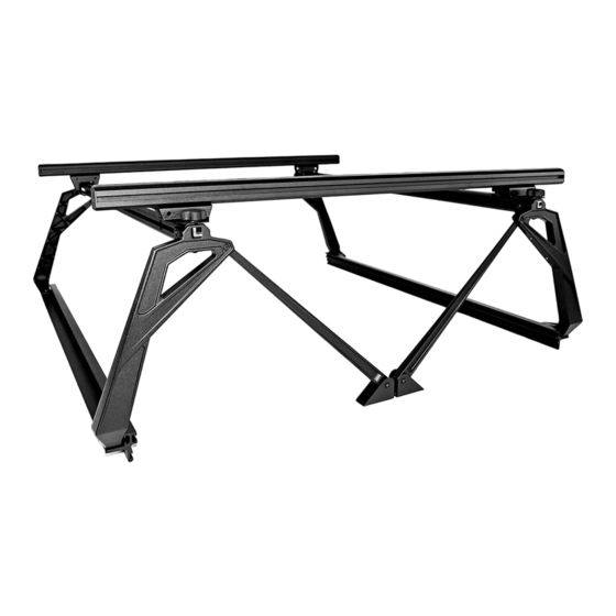
- Page 9 ASSEMBLE ACS side: overview • in the next few steps you will assemble the left and right side portion of the active cargo system. • The illustration bellow shows what the part will look like when fully assembled. You can refer back to this illustration at any time to clarify part location.
- Page 10 ASSEMBLE: top bar • attach a & B upright assembly’s to top bar as shown in illustration below. Do not tighten the M8 bolts at this time. • B upright a upright DETAIL-2 DETAIL-1 V1 | Page 10...
-
Page 11: Assemble: Rail
ASSEMBLE: RAIL • NOTE: left side shown. repeat steps for right side assembly. • Attach rail to uprights using four M10 X 25 screws. Torque to 50n.m using a t40 torx wrench. • Torque all M8 bolts installed in previous step to 20n.m using a t40 torx wrench. Important: Tighten M10x25 rail bolts first then torque the m8 bolts. - Page 12 ASSEMBLE: RAIL CLAMPS TO RAILS • Install three rail clamps onto the left and right side rail that were assembled in previous steps. The rail clamp will slide onto the rail from either end. • NOTE: SOME TRUCK BEDS WILL NOT ALLOW THE CLAMPS TO BE SPACED EVENLY. IN THIS SITUATION IT MIGHT BE NESSISARY TO HAVE 2 CLAMPS NEXT TO EACH OTHER.
- Page 13 INSTALL: RACK TO TRUCK • Place the LEFT SIDE assembly onto the bed rail of the truck. Adjust the clamps so they are evenly spaced and as far apart as possible. Every truck bed is different and you will need to adjust the clamps so that they are at the deepest point in the bed and the rails sit flush.
- Page 14 Install: load bars • SLIDE THE 60” long LOAD BARS ONTO THE T-nuts into the LOAD BAR BRACKETS and centered them on the rack. • Tighten the M8 X 14 bolts on the underside of the brackets making sure the load bars stay centerd V1 | Page 14...
- Page 15 Finish: install end caps and rubber tread strip • Install the rubber tread strip into the upper cross bar channel by pushing it into the t-slot with the palm of your hand. Note: some trimming of the rubber tread strip might be necessary. •...
-
Page 16: Use Guidelines
•All locks must be turned and moved periodically to ensure smooth operation. Use graphite or dry lubricant to help this. Leitner designs locks are designed to deter vandalism and theft but should not be considered theft proof. Remove valuable gear if your vehicle is unattended for an extended period. -
Page 17: Warranty
Warranty Leitner Designs warrants product to be free from defects in material and workmanship, for terms specified below, provided there has been normal use and proper maintenance. All remedies under this warranty are limited to the repair or replacement of any item found by the factory to be defective within the time period specified.
Need help?
Do you have a question about the ACS FORGED and is the answer not in the manual?
Questions and answers