Table of Contents
Advertisement
Quick Links
Advertisement
Table of Contents

Related Manuals for Leitner ACS TONNEAU


Summary of Contents for Leitner ACS TONNEAU
- Page 1 tonneau LEITNERDESIGNS.COM | SALES@LEITNERDESIGNS.COM | 949-395-3049 V1 | Page 1...
-
Page 2: Tools Required
ASSEMBLY / INSTALLATION INSTRUCTIONS: ACTIVE CARGO SYSTEM PART NUMBERS: 00-50-FTA-1375 (5-0’ BED LENGTH) 00-56-FTA-1376 (5-1/2’ BED LENGTH) 00-60-FTA-1377 (6-0’ BED LENGTH) 00-64-FTA-1378 (6’-4” BED LENGTH) 00-66-FTA-1379 (6-1/2’ BED LENGTH) TOOLS REQUIRED INSTALLATION TIME 2-3 Hours Basic knowledge of hand tools required •... -
Page 3: Assembly Overview
▼ READ BEFORE INSTALLING ACTIVE CARGO SYSTEM ▼ 1. retrax XR tonneau must be installed on truck before beginning assembly. 2. Don’t over-tighten bolts. All 10mm bolts = (40lb-ft) All 8mm bolts = (18ft-lb) 3. Lay down a large area of carpet or blankets as a work area to avoid scratching parts during assembly. 4. - Page 4 ▼ ACTIVE CARGO SYSTEM hardware ▼ long t-nut (x12) short t-nut (x4) not used with Tonneau single t-nut compatible rack (x4) m10 x 22 m8 x 20 m8 x 14 1332-tonneau nut (x8) (x16) (x22) (x6] V1 | Page 4...
- Page 5 PREP: load BAR BRACKETs • Install 2 M8 x 14 bolts through bracket and thread into long T-nut. do not tighten at this time. • Repeat steps below for all four bracket. • set aside for use in a later step . long T-Nut m8 x 14 V1 | Page 5...
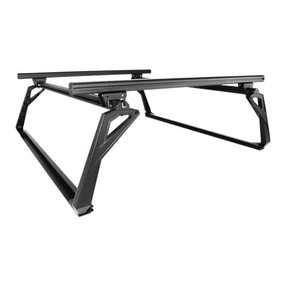
- Page 6 ASSEMBLE ACS side: overview • in the next few steps you will assemble the drivers and passenger side portion of the active cargo system. • The illustration bellow shows what the part will look like when fully assembled. You can refer back to this illustration at any time to clarify part location.
- Page 7 ASSEMBLE: upright “A” • Assemble uprights marked “A” as shown in the folLOwing diagram. •THREAD TWO M8 X 20 BOLTS INTO THE SHORT T-NUT. {FIG-A} DO NOT TIGHTEN AT THIS TIME. •THREAD TWO M8X 20 BOLTS THROUGH CROSS BAR BRACKET AND UPRIGHT INTO LONG T-NUT {FIG-B} DO NOT TIGHTEN AT THIS TIME. •...
- Page 8 ASSEMBLE: upright “B” • Assemble uprights as shown in the following diagram. DO NOT TIGHTEN AT THIS TIME. •THREAD TWO M8 X 20 BOLTS INTO THE SHORT T-NUT. {FIG-A} DO NOT TIGHTEN AT THIS TIME. •THREAD TWO M8X 20 BOLTS THROUGH CROSS BAR BRACKET AND UPRIGHT INTO LONG T-NUT {FIG-B} DO NOT TIGHTEN AT THIS TIME.
- Page 9 ASSEMBLE: top bar Do not tighten bolts at this time. • attach a & B upright assembly’s to top bar as shown in illustration below. B upright a upright DETAIL-2 DETAIL-1 V1 | Page 9...
-
Page 10: Assemble: Rail
ASSEMBLE: RAIL • Attach rail to uprights using four M10 X 25 screws. Torque to 40 Ft-lb using a 6mm allen wrench. • Torque all M8 bolts installed in previous step to 18 ft-lb using a 5mm allen wrench. Important: Tighten M10x25 rail bolts first then torque the m8 bolts. •... - Page 11 ASSEMBLE: install nuts into retrax rails • Install 3 tonneau nuts into each retrax bed rail t-slot. • Space them apart the same distance as the mounting holes in the ACS Tonneau rails. V1 | Page 11...
- Page 12 install: Upright assemblies to truck • this next step is best done using two people to help stabilize the rack assembly!! • Using a M8 X 14 bolt attach the right and left assemblies to the truck. • Make sure both passenger and drivers side are in the same location as measured front to back on the truck bed. V1 | Page 12...
- Page 13 Install: load bars • SLIDE THE 60” long LOAD BARS ONTO THE T-nuts into the LOAD BAR BRACKETS and center them on the rack. • Tighten the M8 X 14 bolts on the underside of the brackets making sure the load bars stay centerd V1 | Page 13...
- Page 14 Finish: install end caps and rubber tread strip • Install the rubber tread strip into the upper cross bar channel by pushing it into the t-slot with the palm of your hand. Note: some trimming of the rubber tread strip might be necessary. •...
-
Page 15: Use Guidelines
•All locks must be turned and moved periodically to ensure smooth operation. Use graphite or dry lubricant to help this. Leitner designs locks are designed to deter vandalism and theft but should not be considered theft proof. Remove valuable gear if your vehicle is unattended for an extended period. -
Page 16: Warranty
Warranty Leitner Designs warrants product to be free from defects in material and workmanship, for terms specified below, provided there has been normal use and proper maintenance. All remedies under this warranty are limited to the repair or replacement of any item found by the factory to be defective within the time period specified.
Need help?
Do you have a question about the ACS TONNEAU and is the answer not in the manual?
Questions and answers