
Related Manuals for Leitner ACS FORGED


Summary of Contents for Leitner ACS FORGED
- Page 1 LEITNER toyota tacoma LEITNERDESIGNS.COM | SALES@LEITNERDESIGNS.COM | 949-395-3049 V1 | Page 1...
-
Page 2: Assembly / Installation Instructions
ASSEMBLY / INSTALLATION INSTRUCTIONS: ACTIVE CARGO SYSTEM PART NUMBERS: 04-60-FA-1307 (2005-2015 Toyota Tacoma Short Bed] 04-73-FA-1328 (2005-2015 Toyota Tacoma Long Bed] 04-60-FA-1311 (2016-2020 Toyota Tacoma Short Bed] 04-73-FA-1329 (2016-2020 Toyota Tacoma Long Bed] TOOLS REQUIRED INSTALLATION TIME 2-3 Hours Basic knowledge of hand tools required •... -
Page 3: Assembly Overview
▼ READ BEFORE INSTALLING ACTIVE CARGO SYSTEM ▼ there are 2 different uprights clearly marked A & B. The A bracket is used on the passenger side by the cab and on the drivers side by the tailgate. the B upright is used by the drivers side cab and passengers side tailgate. - Page 4 ▼ ACTIVE CARGO SYSTEM hardware ▼ long t-nut (x8) short t-nut (x4) single t-nut (x4) m10 x 25 m8 x 14 rail bolt m8 nut m8 t-bolt m8 x 20 (x8) (x16) (x6) (x6) (x4) (x12) endcap knob (x4) (x4) V1 | Page 4...
- Page 5 PREP: STATIONARY load BAR BRACKET • Install 2 M8 x 14 bolts through bracket and thread into long T-nut. do not tighten at this time. • Repeat steps below for second bracket. • set aside for use in a later step . long T-Nut m8 x 14 V1 | Page 5...
- Page 6 PREP: SLIDING load BAR BRACKETS • Install 2 M8 x 14 bolts through bracket and thread into long T-nut. do not tighten at this time. • Repeat steps below for second bracket. • set aside for use in a later step . long T-Nut m8 x 14 V1 | Page 6...
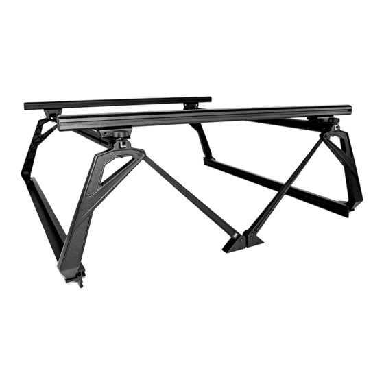
- Page 7 ASSEMBLE driver side: overview • in the next few steps you will assemble the drivers side portion of the active cargo system. • The illustration bellow shows what the part will look like when fully assembled. You can refer back to this illustration at any time to clarify part location.
- Page 8 ASSEMBLE driver side: upright “A” • Assemble upright marked “A” as shown in the following diagram. •THREAD TWO M8 X 20 BOLTS INTO THE SHORT T-NUT. DO NOT TIGHTEN AT THIS TIME. •THREAD ONE M8 X 16 BOLTS INTO EACH ONE OF THE SINGLE T-NUTS. DO NOT TIGHTEN AT THIS TIME. •...
- Page 9 ASSEMBLE driver side: upright “B” • Assemble upright marked “B” as shown in the folLOwing diagram. •THREAD TWO M8 X 20 BOLTS INTO THE SHORT T-NUT. {FIG-A} DO NOT TIGHTEN AT THIS TIME. •THREAD TWO M8X 20 BOLTS THROUGH CROSS BAR BRACKET AND UPRIGHT INTO LONG T-NUT {FIG-B} DO NOT TIGHTEN AT THIS TIME. •...
- Page 10 ASSEMBLE driver side: top bar • attach a & B upright assembles to top bar as shown in illustration below. Do not tighten bolts at this time. •NOTE: MAKE SURE YOU Slide THE TWO (2) T-BOLTS INTO THE UPPER MOST T-TRACK DETAIL-2 DETAIL-1 STOP...
- Page 11 ASSEMBLE driver side: RAIL • attach rail to uprights using four M10 X 25 screws. Torque to 40 Ft-lb using a 6mm allen wrench. • Torque all M8 bolts installed in previous step to 18 ft-lb using a 5mm allen wrench. Important: Tighten M10x25 rail bolts first then torque the m8 bolts.
- Page 12 ASSEMBLE passenger side: overview • in the next few steps you will assemble the passenger side portion of the active cargo system. • The illustration bellow shows what the part will look like when fully assembled. You can refer back to this illustration at any time to clarify part location.
- Page 13 ASSEMBLE passenger side: upright “b” • Assemble upright marked “b” as shown in the following diagram. •THREAD TWO M8 X 20 BOLTS INTO THE SHORT T-NUT. DO NOT TIGHTEN AT THIS TIME. •THREAD ONE M8 X 16 BOLTS INTO EACH ONE OF THE SINGLE T-NUTS. DO NOT TIGHTEN AT THIS TIME. •...
- Page 14 ASSEMBLE passenger side: upright “A” • Assemble upright marked “A” as shown in the folLOwing diagram. •THREAD TWO M8 X 20 BOLTS INTO THE SHORT T-NUT. {FIG-A} DO NOT TIGHTEN AT THIS TIME. •THREAD TWO M8X 20 BOLTS THROUGH CROSS BAR BRACKET AND UPRIGHT INTO LONG T-NUT {FIG-B} DO NOT TIGHTEN AT THIS TIME. •...
- Page 15 ASSEMBLE passenger side: top bar • attach a & B upright assembles to top bar as shoWN in illustration below. Do not tighten bolts at this time. •NOTE: MAKE SURE YOU SLide THE TWO (2) T-BOLTS INTO THE UPPER MOST T-TRACK DETAIL-2 DETAIL-1 STOP...
- Page 16 ASSEMBLE passenger side: RAIL • attach rail to uprights using four M10 X 25 screws. Torque to 40 Ft-lb using a 6mm allen wrench. • Torque all M8 bolts installed in previous step to 16 ft-lb using a 5mm allen wrench. Important: Tighten M10x25 rail bolts first then torque the m8 bolts.
- Page 17 ASSEMBLE: Tacoma down tubes • Remove two M8x14 screws from the upright. Using these screws attach the Tacoma down tubes as shown. V1 | Page 17...
- Page 18 prep: TACOMA BED • Install three rail bolts into both the passenger and drivers side trail rails. • note: you will need to remove the factory tie downs first. V1 | Page 18...
- Page 19 prep: TACOMA BED •REMOVE THE 2 REAR BED BOLTS USING A T55 TORX WRENCH. SET ASIDE FOR USE LATER. • REMOVE THE TWO REAR TIE DOWN RINGS USING A T40 TORX WRENCH. SET ASIDE FOR USE LATER V1 | Page 19...
- Page 20 INSTALL: RACK TO TRUCK • Place the drivers side assembly onto the bed rail of the truck. The “D” will be toward the tailgate. • Align the holes in the Upright supports with the holes in the floor of the trucked, Replace bolts. [Detail - A] •...
- Page 21 ASSEMBLE: front load BAR TO BRACKETS • SLIDE THE 60” long load BARS ONTO THE T-nuts IN THE stationary load BAR BRACKETS and center them on the rack. • Tighten the four M8 screws on the underside of the bracket using a 5mm allen wrench. V1 | Page 21...
- Page 22 ASSEMBLE: SLIDING LOAD BAR BRACKETS • USING 2 rubber knobs per side, SECURE THE rear CROSS BAR BRACKET AS FAR rearward AS POSSIBLE. [Detail A - b] DETAIL-A DETAIL-b V1 | Page 22...
- Page 23 ASSEMBLE: REAR LOAD BAR TO BRACKETS • SLIDE THE 60” long LOAD BARS ONTO THE T-nuts IN THE REAR LOAD BAR BRACKETS and center them on the rack. V1 | Page 23...
- Page 24 finish: install end caps and rubber tread strip • Install the rubber tread strip into the upper cross bar channel by pushing it into the t-slot with the palm of your hand. Note: some trimming of the rubber tread strip might be necessary. •...
-
Page 25: Use Guidelines
•All locks must be turned and moved periodically to ensure smooth operation. Use graphite or dry lubricant to help this. Leitner designs locks are designed to deter vandalism and theft but should not be considered theft proof. Remove valuable gear if your vehicle is unattended for an extended period. -
Page 26: Warranty
Warranty Leitner Designs warrants product to be free from defects in material and workmanship, for terms specified below, provided there has been normal use and proper maintenance. All remedies under this warranty are limited to the repair or replacement of any item found by the factory to be defective within the time period specified.
Need help?
Do you have a question about the ACS FORGED and is the answer not in the manual?
Questions and answers